EP2355290A1 - Schutzschaltung für eine Antriebsschaltung eines Permanentmagnetmotors und entsprechendes System - Google Patents
Schutzschaltung für eine Antriebsschaltung eines Permanentmagnetmotors und entsprechendes System Download PDFInfo
- Publication number
- EP2355290A1 EP2355290A1 EP10152613A EP10152613A EP2355290A1 EP 2355290 A1 EP2355290 A1 EP 2355290A1 EP 10152613 A EP10152613 A EP 10152613A EP 10152613 A EP10152613 A EP 10152613A EP 2355290 A1 EP2355290 A1 EP 2355290A1
- Authority
- EP
- European Patent Office
- Prior art keywords
- protection circuit
- source
- main
- voltage
- protection
- Prior art date
- Legal status (The legal status is an assumption and is not a legal conclusion. Google has not performed a legal analysis and makes no representation as to the accuracy of the status listed.)
- Granted
Links
Images
Classifications
-
- H—ELECTRICITY
- H02—GENERATION; CONVERSION OR DISTRIBUTION OF ELECTRIC POWER
- H02H—EMERGENCY PROTECTIVE CIRCUIT ARRANGEMENTS
- H02H9/00—Emergency protective circuit arrangements for limiting excess current or voltage without disconnection
- H02H9/04—Emergency protective circuit arrangements for limiting excess current or voltage without disconnection responsive to excess voltage
- H02H9/045—Emergency protective circuit arrangements for limiting excess current or voltage without disconnection responsive to excess voltage adapted to a particular application and not provided for elsewhere
- H02H9/047—Free-wheeling circuits
-
- H—ELECTRICITY
- H02—GENERATION; CONVERSION OR DISTRIBUTION OF ELECTRIC POWER
- H02H—EMERGENCY PROTECTIVE CIRCUIT ARRANGEMENTS
- H02H7/00—Emergency protective circuit arrangements specially adapted for specific types of electric machines or apparatus or for sectionalised protection of cable or line systems, and effecting automatic switching in the event of an undesired change from normal working conditions
- H02H7/08—Emergency protective circuit arrangements specially adapted for specific types of electric machines or apparatus or for sectionalised protection of cable or line systems, and effecting automatic switching in the event of an undesired change from normal working conditions for dynamo-electric motors
- H02H7/0833—Emergency protective circuit arrangements specially adapted for specific types of electric machines or apparatus or for sectionalised protection of cable or line systems, and effecting automatic switching in the event of an undesired change from normal working conditions for dynamo-electric motors for electric motors with control arrangements
- H02H7/0838—Emergency protective circuit arrangements specially adapted for specific types of electric machines or apparatus or for sectionalised protection of cable or line systems, and effecting automatic switching in the event of an undesired change from normal working conditions for dynamo-electric motors for electric motors with control arrangements with H-bridge circuit
-
- H—ELECTRICITY
- H02—GENERATION; CONVERSION OR DISTRIBUTION OF ELECTRIC POWER
- H02H—EMERGENCY PROTECTIVE CIRCUIT ARRANGEMENTS
- H02H7/00—Emergency protective circuit arrangements specially adapted for specific types of electric machines or apparatus or for sectionalised protection of cable or line systems, and effecting automatic switching in the event of an undesired change from normal working conditions
- H02H7/10—Emergency protective circuit arrangements specially adapted for specific types of electric machines or apparatus or for sectionalised protection of cable or line systems, and effecting automatic switching in the event of an undesired change from normal working conditions for converters; for rectifiers
- H02H7/12—Emergency protective circuit arrangements specially adapted for specific types of electric machines or apparatus or for sectionalised protection of cable or line systems, and effecting automatic switching in the event of an undesired change from normal working conditions for converters; for rectifiers for static converters or rectifiers
- H02H7/122—Emergency protective circuit arrangements specially adapted for specific types of electric machines or apparatus or for sectionalised protection of cable or line systems, and effecting automatic switching in the event of an undesired change from normal working conditions for converters; for rectifiers for static converters or rectifiers for inverters, i.e. DC/AC converters
- H02H7/1227—Emergency protective circuit arrangements specially adapted for specific types of electric machines or apparatus or for sectionalised protection of cable or line systems, and effecting automatic switching in the event of an undesired change from normal working conditions for converters; for rectifiers for static converters or rectifiers for inverters, i.e. DC/AC converters responsive to abnormalities in the output circuit, e.g. short circuit
Definitions
- the present invention relates generally to control of permanent magnet electrical motors, and more particularly to control of permanent magnet electrical motors during fault conditions.
- JP-2000 184 770 presents a solution where breakers are used to cut off an electrical connection between inverter and a permanent magnet AC motor.
- breakers are relatively slow and a faster solution would reduce any ill-effects during a fault.
- An object of the present invention is thus to improve fault handling for drives using permanent magnet motors.
- a protection circuit for a drive circuit of a permanent magnet motor the protection circuit being powered by a main DC source.
- the protection circuit comprises: a protection circuit DC source; a changeover switch being arranged to select an input to a gate of a main drive switch of the drive circuit, the input being selectable between an output of the protection circuit DC source and a second control signal; and a changeover control device connected to control the changeover switch, which changeover control device is arranged to ensure that the changeover switch is connected to the output of the second side of the protection circuit DC source when an overvoltage is detected.
- the main drive switch can be turned on quickly and efficiently when an overvoltage is detected.
- the changeover control device may comprises a comparator.
- the changeover control device may be arranged to compare a voltage selected between two poles of the main DC source with a reference voltage.
- Each one of two inputs of the comparator may be connected to a respective voltage divider.
- the protection circuit DC source may comprise a DC to DC converter with a first side and a second side, wherein the first side is arranged to be connected to a main DC source for the drive circuit.
- the output of the DC to DC converter may have a voltage difference of less than one tenth of the voltage difference of the input of the DC to DC converter.
- the comparator may comprise hysteresis.
- the protection circuit DC source may comprise an energy storage.
- a second aspect of the invention is a protection circuit system comprising a plurality of protection circuits according to the first aspect, wherein the number of protection circuits corresponds to the number of phases of the permanent magnet motor.
- the protection circuit system may consist of three protection circuits.
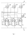
- Fig 1 is a schematic diagram of an environment where a protection circuit according to an embodiment of the present invention can be applied.
- a three-phase permanent magnet synchronous motor 50 is powered through three AC (Alternating Current) inputs 32u, 32v, 32w.
- the motor can be used for any suitable purpose, where one example is to drive a vehicle. In such a context the vehicle could be provided with two or more systems as shown in Fig 1 to drive two or more wheels of the vehicle, respectively.
- Another application can be a motor 50 that is mounted onto a diesel motor output shaft and used as a generator.
- a bridge leg inverter system is used where the inputs 32u, 32v, 32w are switched between a positive DC voltage 30 and a negative DC voltage 31.
- the difference in voltage between the positive and the negative DC voltages 30, 31 typically ranges between 300 and 900 volts.
- the positive and negative DC voltages can be symmetrical or asymmetrical about zero or one could be zero.
- the DC voltages 30 and 31 can in turn be created from a rectified AC source or from another DC source such as a battery or fuel cell.
- the switching is performed in main drive switches 21u and 22u for a u-phase, in main drive switches 21v and 22v for a v-phase and in main drive switches 21w and 22w for a w-phase.
- the main drive switches 21u, 21v, 21w, 22u, 22v, 22w can be insulated-gate bipolar transistors (IGBT) or any other suitable switch.
- IGBT insulated-gate bipolar transistors
- Each main drive switch 21u, 21v, 21w, 22u, 22v, 22w can have a corresponding gate drive circuit (not shown) between a controller and its gate.
- each gate drive circuit is controlled from an output (typically a digital output) of a controller 40 to effect pulse width modulation (PWM) as desired from the controller 40.
- PWM pulse width modulation
- the controller 40 can thus control the frequency and power supplied to/from the motor/generator 50.
- each phase has one protection circuit 1u, 1v, 1w, respectively.
- Each protection circuit 1u, 1v, 1w comprises a DC source 12u, 12v, 12w, a changeover switch 10u, 10v, 10w and a changeover control device 11u, 11v, 11w, respectively.
- the changeover control device 11u, 11v, and/or 11w will control its respective changeover switch 10u, 10v, 10w to connect the gate of the respective main drive switch 21u, 21v, 21w to the respective DC source 12u, 12v, 12w.
- protection circuits 1u, 1v, 1w three independent protection arrangements for dc overvoltage are provided. It is sufficient if one of these protection circuits 1u, 1v, 1w is working in order to save the drive system from catastrophic failure. This is because the other main switches contain rectifier diodes that will always conduct in one direction without active control.
- protection circuits 1u, 1v, 1w are depicted connected to the lower switches 21u, 21v, 21w, the protection circuits 1u, 1v, 1w could equally well be connected to the upper switches 22u, 22v, 22w.
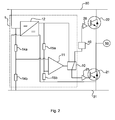
- Fig 2 illustrates one leg of the system of Fig 1 , including more details of its protection circuit 1.
- the illustrated leg can be any of the three legs of Fig 1 since all three legs have the same configuration in this regard.
- the controller 40 can thus, using pulse width modulation, control the main drive switches 21, 22 to provide an AC current of desired frequency and power to the motor 50.
- a protection circuit DC source 12 is here in the form of a DC to DC converter.
- the DC to DC converter converts the main DC voltage 30, 31, used to drive the motor, to an output voltage suitable for controlling the main switch.
- the DC to DC converter outputs a DC voltage which is less than one tenth of the main DC voltage 30, 31.
- the protection circuit DC source can be provided with an energy storage such as a battery or a capacitor. The energy storage allows the protection circuit 1 to operate even if the main DC source 30, 31 fails.
- the power requirements of the DC source are relatively low if it is only used to power the protection circuit 1.
- the continuous power output of the DC source is in the range of 0.2 to 5 Watts.
- the voltage of the output of the DC source can, for example, be between 10 and 20 Volts.
- One terminal of the output of the protection circuit DC source is connected to the negative main DC voltage 31. It is to be noted that the DC source can alternatively be implemented using a separate battery or low voltage DC circuit.
- the changeover control device 11 is a comparator with two inputs. On one input the DC voltage of the main DC source 30, 31 is connected, which voltage is divided by resistors 14a, b. On the other input of the comparator a reference voltage is applied, for example the DC output voltage of the DC source 12, as divided by resistors 15a, b. The comparator thus compares the main DC voltage with a reference voltage provided from the DC source 12.
- the comparator 11 can be implemented using an operational amplifier or a dedicated voltage comparator semiconductor.
- comparator comprises hysteresis to prevent jumping back and forth in the case that the inputs of the comparator are very similar in magnitude.
- the comparator controls the changeover switch 10 such that the gate of the lower main drive switch 21 is connected to, and thereby controlled by, the controller 40.
- the changeover switch 10 is any suitable analogue or digital switch with response times that are sufficiently fast. For example, a one microsecond response time will be sufficient in most cases.
- the comparator 11 will be triggered to alter its state, and thereby control the changeover switch 10 such that the gate of the lower main drive switch 21 is connected to the upper output of the DC source 12. This saturates the lower main drive switch 21 which connects the terminal of the motor 50 to the negative main DC source 31. Before the lower switch 21 is turned on a signal is sent back to the controller 40 so that it will turn off the upper main switches 22.
- a protection circuit 1 is achieved which is fast enough to protect components of the drive circuit from overvoltages in the case of a fault. Moreover, it is sufficient for only one protection circuit 1 to be operational to protect the entire drive circuit, resulting in redundant protection.
- Another fault condition when the motor is rotating at a high speed, could be that the controller 40 fails, which could lead to the motor being uncontrolled.
- the permanent magnets will then generate an AC voltage that is rectified by the diodes in the main switches 21, 22 resulting in a mains DC-over-voltage 30, 31 which would be detected by the comparator in the embodiments described herein.
- a fault condition as described above for one drive system would make the motor for one wheel inoperable. This could be detected by a central control system (not shown) which could disconnect the drive system for that wheel, e.g. using contactors. This allows the vehicle to remain operable, albeit with reduced power.
Landscapes
- Dc-Dc Converters (AREA)
- Inverter Devices (AREA)
- Electric Propulsion And Braking For Vehicles (AREA)
Priority Applications (2)
| Application Number | Priority Date | Filing Date | Title |
|---|---|---|---|
| EP10152613.5A EP2355290B1 (de) | 2010-02-04 | 2010-02-04 | Schutzschaltung für eine Antriebsschaltung eines Permanentmagnetmotors und entsprechendes System |
| US13/020,481 US8598835B2 (en) | 2010-02-04 | 2011-02-03 | Protection circuit for a drive circuit of a permanent magnet motor and corresponding system |
Applications Claiming Priority (1)
| Application Number | Priority Date | Filing Date | Title |
|---|---|---|---|
| EP10152613.5A EP2355290B1 (de) | 2010-02-04 | 2010-02-04 | Schutzschaltung für eine Antriebsschaltung eines Permanentmagnetmotors und entsprechendes System |
Publications (2)
| Publication Number | Publication Date |
|---|---|
| EP2355290A1 true EP2355290A1 (de) | 2011-08-10 |
| EP2355290B1 EP2355290B1 (de) | 2017-04-26 |
Family
ID=42224626
Family Applications (1)
| Application Number | Title | Priority Date | Filing Date |
|---|---|---|---|
| EP10152613.5A Active EP2355290B1 (de) | 2010-02-04 | 2010-02-04 | Schutzschaltung für eine Antriebsschaltung eines Permanentmagnetmotors und entsprechendes System |
Country Status (2)
| Country | Link |
|---|---|
| US (1) | US8598835B2 (de) |
| EP (1) | EP2355290B1 (de) |
Families Citing this family (2)
| Publication number | Priority date | Publication date | Assignee | Title |
|---|---|---|---|---|
| CN104052373B (zh) | 2013-03-14 | 2017-04-12 | 通用电气公司 | 电机故障保护系统和方法 |
| CN121664027B (zh) * | 2026-02-06 | 2026-04-14 | 厦门海洋职业技术学院 | 一种无刷直流电机的放电系统和放电方法 |
Citations (6)
| Publication number | Priority date | Publication date | Assignee | Title |
|---|---|---|---|---|
| EP0444484A2 (de) * | 1990-02-26 | 1991-09-04 | Motorola, Inc. | Überspannungsschutzschaltung |
| EP0596472A2 (de) * | 1992-11-03 | 1994-05-11 | Texas Instruments Deutschland Gmbh | Schaltungsanordnung zur Speisung einer induktiven Last |
| JP2000184770A (ja) | 1998-12-10 | 2000-06-30 | Fuji Electric Co Ltd | 永久磁石同期電動機の駆動方法 |
| US20080130178A1 (en) * | 2006-12-04 | 2008-06-05 | Magna Electronics | Load dump protection for power fet device |
| WO2008122602A1 (de) * | 2007-04-05 | 2008-10-16 | Siemens Aktiengesellschaft | Überspannungsschutz für einen umrichter |
| US20080304189A1 (en) * | 2007-06-06 | 2008-12-11 | David Tang | Protection for permanent magnet motor control circuits |
Family Cites Families (11)
| Publication number | Priority date | Publication date | Assignee | Title |
|---|---|---|---|---|
| US4873453A (en) * | 1987-10-27 | 1989-10-10 | Eaton Corporation | DC motor speed controller having protection |
| US5513058A (en) * | 1994-03-03 | 1996-04-30 | General Electric Company | DC link circuit for an electronically commutated motor |
| EP0710600B1 (de) * | 1994-11-04 | 2001-10-24 | Trw Inc. | Verfahren und Vorrichtung zur Steuerung eines Elektromotors |
| US6020702A (en) * | 1998-01-12 | 2000-02-01 | Tecumseh Products Company | Single phase compressor thermostat with start relay and motor protection |
| DE102004018823B3 (de) * | 2004-04-19 | 2005-06-30 | Infineon Technologies Ag | Schaltungsanordnung mit einem Leistungstransistor und einer Ansteuerschaltung für den Leistungstransistor |
| JP4360310B2 (ja) * | 2004-10-22 | 2009-11-11 | サンケン電気株式会社 | 駆動装置 |
| DE102005009465A1 (de) * | 2005-03-02 | 2006-09-07 | Robert Bosch Gmbh | Transistoranordnung für Gleich- und Wechselrichter |
| JP2008123276A (ja) * | 2006-11-13 | 2008-05-29 | Sharp Corp | 定電圧出力回路 |
| FR2911736B1 (fr) * | 2007-01-23 | 2009-03-20 | Schneider Toshiba Inverter | Dispositif de commande d'un interrupteur de puissance et variateur comprenant un tel dipositif. |
| EP2197111B1 (de) * | 2008-12-15 | 2012-06-20 | Danaher Motion Stockholm AB | Gate-Treiberschaltung, Schalteranordnung und Schaltersystem |
| JP5513829B2 (ja) * | 2009-10-01 | 2014-06-04 | パナソニック株式会社 | 電流駆動回路 |
-
2010
- 2010-02-04 EP EP10152613.5A patent/EP2355290B1/de active Active
-
2011
- 2011-02-03 US US13/020,481 patent/US8598835B2/en active Active
Patent Citations (6)
| Publication number | Priority date | Publication date | Assignee | Title |
|---|---|---|---|---|
| EP0444484A2 (de) * | 1990-02-26 | 1991-09-04 | Motorola, Inc. | Überspannungsschutzschaltung |
| EP0596472A2 (de) * | 1992-11-03 | 1994-05-11 | Texas Instruments Deutschland Gmbh | Schaltungsanordnung zur Speisung einer induktiven Last |
| JP2000184770A (ja) | 1998-12-10 | 2000-06-30 | Fuji Electric Co Ltd | 永久磁石同期電動機の駆動方法 |
| US20080130178A1 (en) * | 2006-12-04 | 2008-06-05 | Magna Electronics | Load dump protection for power fet device |
| WO2008122602A1 (de) * | 2007-04-05 | 2008-10-16 | Siemens Aktiengesellschaft | Überspannungsschutz für einen umrichter |
| US20080304189A1 (en) * | 2007-06-06 | 2008-12-11 | David Tang | Protection for permanent magnet motor control circuits |
Also Published As
| Publication number | Publication date |
|---|---|
| US20110188158A1 (en) | 2011-08-04 |
| US8598835B2 (en) | 2013-12-03 |
| EP2355290B1 (de) | 2017-04-26 |
Similar Documents
| Publication | Publication Date | Title |
|---|---|---|
| US9106155B2 (en) | Three-level power conversion circuit system | |
| CN102812631B (zh) | 电动机驱动装置 | |
| CN102771042B (zh) | 控制多相电机的方法和装置 | |
| EP2675060A1 (de) | Stromrichter | |
| US9024564B2 (en) | Drive control device and drive control method | |
| US12110068B2 (en) | Control for electric power steering | |
| JP2014180197A (ja) | モータの故障保護のためのシステムおよび方法 | |
| CN110710090B (zh) | Dc链路电容器保护 | |
| JP6305495B1 (ja) | インバータ制御装置及びインバータ制御方法 | |
| JP2007252192A (ja) | 電気自動車及びハイブリッド自動車のためのy字スイッチインバータ | |
| US20170005568A1 (en) | In situ overvoltage protection for active bridge applications | |
| CN105429500A (zh) | 用于电机的逆变电路 | |
| JP2013511249A (ja) | インバータ用パワースイッチ装置 | |
| US20120229068A1 (en) | Inverter | |
| US20120217918A1 (en) | Inverter | |
| EP2355290B1 (de) | Schutzschaltung für eine Antriebsschaltung eines Permanentmagnetmotors und entsprechendes System | |
| JP2017195734A (ja) | 交流回転機の制御装置及び制御方法 | |
| CN111641235A (zh) | 电气驱动器 | |
| CN112739568A (zh) | 逆变器的控制装置、车辆的逆变器、车辆及操作逆变器的方法 | |
| JP2006314184A (ja) | モータ装置 | |
| JP2016127677A (ja) | 電力変換装置 | |
| US20250379511A1 (en) | Power system with a power converter | |
| CN103124154B (zh) | 频率转换器中的控制安排 | |
| JP2025042177A (ja) | モータ駆動回路 | |
| KR20160053012A (ko) | 전동기 구동 장치 및 전동기 구동 장치의 에너지 저장 방법 |
Legal Events
| Date | Code | Title | Description |
|---|---|---|---|
| PUAI | Public reference made under article 153(3) epc to a published international application that has entered the european phase |
Free format text: ORIGINAL CODE: 0009012 |
|
| AK | Designated contracting states |
Kind code of ref document: A1 Designated state(s): AT BE BG CH CY CZ DE DK EE ES FI FR GB GR HR HU IE IS IT LI LT LU LV MC MK MT NL NO PL PT RO SE SI SK SM TR |
|
| AX | Request for extension of the european patent |
Extension state: AL BA RS |
|
| 17P | Request for examination filed |
Effective date: 20120209 |
|
| RAP1 | Party data changed (applicant data changed or rights of an application transferred) |
Owner name: INMOTION TECHNOLOGIES AB |
|
| GRAP | Despatch of communication of intention to grant a patent |
Free format text: ORIGINAL CODE: EPIDOSNIGR1 |
|
| GRAJ | Information related to disapproval of communication of intention to grant by the applicant or resumption of examination proceedings by the epo deleted |
Free format text: ORIGINAL CODE: EPIDOSDIGR1 |
|
| GRAJ | Information related to disapproval of communication of intention to grant by the applicant or resumption of examination proceedings by the epo deleted |
Free format text: ORIGINAL CODE: EPIDOSDIGR1 |
|
| GRAP | Despatch of communication of intention to grant a patent |
Free format text: ORIGINAL CODE: EPIDOSNIGR1 |
|
| RIC1 | Information provided on ipc code assigned before grant |
Ipc: H02H 7/122 20060101ALN20160929BHEP Ipc: H02H 7/08 20060101ALN20160929BHEP Ipc: H02H 9/04 20060101AFI20160929BHEP |
|
| INTG | Intention to grant announced |
Effective date: 20161021 |
|
| GRAP | Despatch of communication of intention to grant a patent |
Free format text: ORIGINAL CODE: EPIDOSNIGR1 |
|
| INTG | Intention to grant announced |
Effective date: 20161104 |
|
| INTC | Intention to grant announced (deleted) | ||
| INTG | Intention to grant announced |
Effective date: 20161130 |
|
| GRAS | Grant fee paid |
Free format text: ORIGINAL CODE: EPIDOSNIGR3 |
|
| GRAA | (expected) grant |
Free format text: ORIGINAL CODE: 0009210 |
|
| AK | Designated contracting states |
Kind code of ref document: B1 Designated state(s): AT BE BG CH CY CZ DE DK EE ES FI FR GB GR HR HU IE IS IT LI LT LU LV MC MK MT NL NO PL PT RO SE SI SK SM TR |
|
| REG | Reference to a national code |
Ref country code: GB Ref legal event code: FG4D |
|
| REG | Reference to a national code |
Ref country code: CH Ref legal event code: EP |
|
| REG | Reference to a national code |
Ref country code: AT Ref legal event code: REF Ref document number: 888631 Country of ref document: AT Kind code of ref document: T Effective date: 20170515 |
|
| REG | Reference to a national code |
Ref country code: IE Ref legal event code: FG4D |
|
| REG | Reference to a national code |
Ref country code: DE Ref legal event code: R096 Ref document number: 602010041795 Country of ref document: DE |
|
| REG | Reference to a national code |
Ref country code: NL Ref legal event code: MP Effective date: 20170426 |
|
| REG | Reference to a national code |
Ref country code: LT Ref legal event code: MG4D |
|
| REG | Reference to a national code |
Ref country code: AT Ref legal event code: MK05 Ref document number: 888631 Country of ref document: AT Kind code of ref document: T Effective date: 20170426 |
|
| PG25 | Lapsed in a contracting state [announced via postgrant information from national office to epo] |
Ref country code: NL Free format text: LAPSE BECAUSE OF FAILURE TO SUBMIT A TRANSLATION OF THE DESCRIPTION OR TO PAY THE FEE WITHIN THE PRESCRIBED TIME-LIMIT Effective date: 20170426 |
|
| PG25 | Lapsed in a contracting state [announced via postgrant information from national office to epo] |
Ref country code: GR Free format text: LAPSE BECAUSE OF FAILURE TO SUBMIT A TRANSLATION OF THE DESCRIPTION OR TO PAY THE FEE WITHIN THE PRESCRIBED TIME-LIMIT Effective date: 20170727 Ref country code: AT Free format text: LAPSE BECAUSE OF FAILURE TO SUBMIT A TRANSLATION OF THE DESCRIPTION OR TO PAY THE FEE WITHIN THE PRESCRIBED TIME-LIMIT Effective date: 20170426 Ref country code: NO Free format text: LAPSE BECAUSE OF FAILURE TO SUBMIT A TRANSLATION OF THE DESCRIPTION OR TO PAY THE FEE WITHIN THE PRESCRIBED TIME-LIMIT Effective date: 20170726 Ref country code: HR Free format text: LAPSE BECAUSE OF FAILURE TO SUBMIT A TRANSLATION OF THE DESCRIPTION OR TO PAY THE FEE WITHIN THE PRESCRIBED TIME-LIMIT Effective date: 20170426 Ref country code: FI Free format text: LAPSE BECAUSE OF FAILURE TO SUBMIT A TRANSLATION OF THE DESCRIPTION OR TO PAY THE FEE WITHIN THE PRESCRIBED TIME-LIMIT Effective date: 20170426 Ref country code: LT Free format text: LAPSE BECAUSE OF FAILURE TO SUBMIT A TRANSLATION OF THE DESCRIPTION OR TO PAY THE FEE WITHIN THE PRESCRIBED TIME-LIMIT Effective date: 20170426 Ref country code: ES Free format text: LAPSE BECAUSE OF FAILURE TO SUBMIT A TRANSLATION OF THE DESCRIPTION OR TO PAY THE FEE WITHIN THE PRESCRIBED TIME-LIMIT Effective date: 20170426 |
|
| PG25 | Lapsed in a contracting state [announced via postgrant information from national office to epo] |
Ref country code: IS Free format text: LAPSE BECAUSE OF FAILURE TO SUBMIT A TRANSLATION OF THE DESCRIPTION OR TO PAY THE FEE WITHIN THE PRESCRIBED TIME-LIMIT Effective date: 20170826 Ref country code: SE Free format text: LAPSE BECAUSE OF FAILURE TO SUBMIT A TRANSLATION OF THE DESCRIPTION OR TO PAY THE FEE WITHIN THE PRESCRIBED TIME-LIMIT Effective date: 20170426 Ref country code: BG Free format text: LAPSE BECAUSE OF FAILURE TO SUBMIT A TRANSLATION OF THE DESCRIPTION OR TO PAY THE FEE WITHIN THE PRESCRIBED TIME-LIMIT Effective date: 20170726 Ref country code: PL Free format text: LAPSE BECAUSE OF FAILURE TO SUBMIT A TRANSLATION OF THE DESCRIPTION OR TO PAY THE FEE WITHIN THE PRESCRIBED TIME-LIMIT Effective date: 20170426 Ref country code: LV Free format text: LAPSE BECAUSE OF FAILURE TO SUBMIT A TRANSLATION OF THE DESCRIPTION OR TO PAY THE FEE WITHIN THE PRESCRIBED TIME-LIMIT Effective date: 20170426 |
|
| REG | Reference to a national code |
Ref country code: DE Ref legal event code: R097 Ref document number: 602010041795 Country of ref document: DE |
|
| PG25 | Lapsed in a contracting state [announced via postgrant information from national office to epo] |
Ref country code: DK Free format text: LAPSE BECAUSE OF FAILURE TO SUBMIT A TRANSLATION OF THE DESCRIPTION OR TO PAY THE FEE WITHIN THE PRESCRIBED TIME-LIMIT Effective date: 20170426 Ref country code: EE Free format text: LAPSE BECAUSE OF FAILURE TO SUBMIT A TRANSLATION OF THE DESCRIPTION OR TO PAY THE FEE WITHIN THE PRESCRIBED TIME-LIMIT Effective date: 20170426 Ref country code: SK Free format text: LAPSE BECAUSE OF FAILURE TO SUBMIT A TRANSLATION OF THE DESCRIPTION OR TO PAY THE FEE WITHIN THE PRESCRIBED TIME-LIMIT Effective date: 20170426 Ref country code: RO Free format text: LAPSE BECAUSE OF FAILURE TO SUBMIT A TRANSLATION OF THE DESCRIPTION OR TO PAY THE FEE WITHIN THE PRESCRIBED TIME-LIMIT Effective date: 20170426 Ref country code: CZ Free format text: LAPSE BECAUSE OF FAILURE TO SUBMIT A TRANSLATION OF THE DESCRIPTION OR TO PAY THE FEE WITHIN THE PRESCRIBED TIME-LIMIT Effective date: 20170426 |
|
| REG | Reference to a national code |
Ref country code: FR Ref legal event code: PLFP Year of fee payment: 9 |
|
| PG25 | Lapsed in a contracting state [announced via postgrant information from national office to epo] |
Ref country code: SM Free format text: LAPSE BECAUSE OF FAILURE TO SUBMIT A TRANSLATION OF THE DESCRIPTION OR TO PAY THE FEE WITHIN THE PRESCRIBED TIME-LIMIT Effective date: 20170426 |
|
| PLBE | No opposition filed within time limit |
Free format text: ORIGINAL CODE: 0009261 |
|
| STAA | Information on the status of an ep patent application or granted ep patent |
Free format text: STATUS: NO OPPOSITION FILED WITHIN TIME LIMIT |
|
| 26N | No opposition filed |
Effective date: 20180129 |
|
| PG25 | Lapsed in a contracting state [announced via postgrant information from national office to epo] |
Ref country code: SI Free format text: LAPSE BECAUSE OF FAILURE TO SUBMIT A TRANSLATION OF THE DESCRIPTION OR TO PAY THE FEE WITHIN THE PRESCRIBED TIME-LIMIT Effective date: 20170426 |
|
| REG | Reference to a national code |
Ref country code: CH Ref legal event code: PL |
|
| PG25 | Lapsed in a contracting state [announced via postgrant information from national office to epo] |
Ref country code: MC Free format text: LAPSE BECAUSE OF FAILURE TO SUBMIT A TRANSLATION OF THE DESCRIPTION OR TO PAY THE FEE WITHIN THE PRESCRIBED TIME-LIMIT Effective date: 20170426 |
|
| GBPC | Gb: european patent ceased through non-payment of renewal fee |
Effective date: 20180204 |
|
| REG | Reference to a national code |
Ref country code: IE Ref legal event code: MM4A |
|
| REG | Reference to a national code |
Ref country code: BE Ref legal event code: MM Effective date: 20180228 |
|
| PG25 | Lapsed in a contracting state [announced via postgrant information from national office to epo] |
Ref country code: LI Free format text: LAPSE BECAUSE OF NON-PAYMENT OF DUE FEES Effective date: 20180228 Ref country code: LU Free format text: LAPSE BECAUSE OF NON-PAYMENT OF DUE FEES Effective date: 20180204 Ref country code: CH Free format text: LAPSE BECAUSE OF NON-PAYMENT OF DUE FEES Effective date: 20180228 |
|
| PG25 | Lapsed in a contracting state [announced via postgrant information from national office to epo] |
Ref country code: IE Free format text: LAPSE BECAUSE OF NON-PAYMENT OF DUE FEES Effective date: 20180204 |
|
| PG25 | Lapsed in a contracting state [announced via postgrant information from national office to epo] |
Ref country code: BE Free format text: LAPSE BECAUSE OF NON-PAYMENT OF DUE FEES Effective date: 20180228 Ref country code: GB Free format text: LAPSE BECAUSE OF NON-PAYMENT OF DUE FEES Effective date: 20180204 |
|
| PG25 | Lapsed in a contracting state [announced via postgrant information from national office to epo] |
Ref country code: MT Free format text: LAPSE BECAUSE OF NON-PAYMENT OF DUE FEES Effective date: 20180204 |
|
| PG25 | Lapsed in a contracting state [announced via postgrant information from national office to epo] |
Ref country code: TR Free format text: LAPSE BECAUSE OF FAILURE TO SUBMIT A TRANSLATION OF THE DESCRIPTION OR TO PAY THE FEE WITHIN THE PRESCRIBED TIME-LIMIT Effective date: 20170426 |
|
| PG25 | Lapsed in a contracting state [announced via postgrant information from national office to epo] |
Ref country code: HU Free format text: LAPSE BECAUSE OF FAILURE TO SUBMIT A TRANSLATION OF THE DESCRIPTION OR TO PAY THE FEE WITHIN THE PRESCRIBED TIME-LIMIT; INVALID AB INITIO Effective date: 20100204 Ref country code: PT Free format text: LAPSE BECAUSE OF FAILURE TO SUBMIT A TRANSLATION OF THE DESCRIPTION OR TO PAY THE FEE WITHIN THE PRESCRIBED TIME-LIMIT Effective date: 20170426 |
|
| PG25 | Lapsed in a contracting state [announced via postgrant information from national office to epo] |
Ref country code: MK Free format text: LAPSE BECAUSE OF NON-PAYMENT OF DUE FEES Effective date: 20170426 Ref country code: CY Free format text: LAPSE BECAUSE OF FAILURE TO SUBMIT A TRANSLATION OF THE DESCRIPTION OR TO PAY THE FEE WITHIN THE PRESCRIBED TIME-LIMIT Effective date: 20170426 |
|
| P01 | Opt-out of the competence of the unified patent court (upc) registered |
Effective date: 20230323 |
|
| PGFP | Annual fee paid to national office [announced via postgrant information from national office to epo] |
Ref country code: DE Payment date: 20260217 Year of fee payment: 17 |
|
| PGFP | Annual fee paid to national office [announced via postgrant information from national office to epo] |
Ref country code: IT Payment date: 20260223 Year of fee payment: 17 |
|
| PGFP | Annual fee paid to national office [announced via postgrant information from national office to epo] |
Ref country code: FR Payment date: 20260217 Year of fee payment: 17 |