EP2355319A2 - Leistungsumwandlungsvorrichtung - Google Patents
Leistungsumwandlungsvorrichtung Download PDFInfo
- Publication number
- EP2355319A2 EP2355319A2 EP11153943A EP11153943A EP2355319A2 EP 2355319 A2 EP2355319 A2 EP 2355319A2 EP 11153943 A EP11153943 A EP 11153943A EP 11153943 A EP11153943 A EP 11153943A EP 2355319 A2 EP2355319 A2 EP 2355319A2
- Authority
- EP
- European Patent Office
- Prior art keywords
- phase
- control
- switching elements
- motor
- power
- Prior art date
- Legal status (The legal status is an assumption and is not a legal conclusion. Google has not performed a legal analysis and makes no representation as to the accuracy of the status listed.)
- Withdrawn
Links
- 238000006243 chemical reaction Methods 0.000 title claims abstract description 138
- 238000000034 method Methods 0.000 claims abstract description 105
- 230000001052 transient effect Effects 0.000 claims description 48
- 230000008859 change Effects 0.000 claims description 34
- 230000007423 decrease Effects 0.000 claims description 12
- 230000007704 transition Effects 0.000 claims description 12
- 230000003247 decreasing effect Effects 0.000 claims description 5
- 230000000875 corresponding effect Effects 0.000 description 25
- 230000008030 elimination Effects 0.000 description 25
- 238000003379 elimination reaction Methods 0.000 description 25
- 239000003990 capacitor Substances 0.000 description 18
- 230000010349 pulsation Effects 0.000 description 18
- 238000012545 processing Methods 0.000 description 14
- 238000001514 detection method Methods 0.000 description 13
- 230000006870 function Effects 0.000 description 13
- 238000004364 calculation method Methods 0.000 description 11
- 230000009467 reduction Effects 0.000 description 10
- 230000001276 controlling effect Effects 0.000 description 9
- 238000004804 winding Methods 0.000 description 8
- 230000009286 beneficial effect Effects 0.000 description 7
- 230000007246 mechanism Effects 0.000 description 7
- 230000000694 effects Effects 0.000 description 5
- 230000005611 electricity Effects 0.000 description 5
- 238000012423 maintenance Methods 0.000 description 5
- 238000004519 manufacturing process Methods 0.000 description 5
- 230000008569 process Effects 0.000 description 5
- 230000001360 synchronised effect Effects 0.000 description 5
- 238000009826 distribution Methods 0.000 description 4
- 239000011159 matrix material Substances 0.000 description 4
- 238000012546 transfer Methods 0.000 description 4
- 230000001133 acceleration Effects 0.000 description 3
- 230000008901 benefit Effects 0.000 description 3
- 230000006698 induction Effects 0.000 description 3
- 230000004043 responsiveness Effects 0.000 description 3
- 239000004065 semiconductor Substances 0.000 description 3
- 229910052770 Uranium Inorganic materials 0.000 description 2
- 238000013459 approach Methods 0.000 description 2
- 238000010586 diagram Methods 0.000 description 2
- 230000005669 field effect Effects 0.000 description 2
- 238000009499 grossing Methods 0.000 description 2
- 238000007493 shaping process Methods 0.000 description 2
- 238000001228 spectrum Methods 0.000 description 2
- 101100042630 Caenorhabditis elegans sin-3 gene Proteins 0.000 description 1
- 230000002547 anomalous effect Effects 0.000 description 1
- 238000004422 calculation algorithm Methods 0.000 description 1
- 238000004590 computer program Methods 0.000 description 1
- 230000002596 correlated effect Effects 0.000 description 1
- 125000004122 cyclic group Chemical group 0.000 description 1
- 230000003111 delayed effect Effects 0.000 description 1
- 239000000284 extract Substances 0.000 description 1
- 230000017525 heat dissipation Effects 0.000 description 1
- 230000020169 heat generation Effects 0.000 description 1
- 238000003384 imaging method Methods 0.000 description 1
- 229910044991 metal oxide Inorganic materials 0.000 description 1
- 150000004706 metal oxides Chemical class 0.000 description 1
- 230000003534 oscillatory effect Effects 0.000 description 1
- 230000001172 regenerating effect Effects 0.000 description 1
- 238000011160 research Methods 0.000 description 1
- 230000002441 reversible effect Effects 0.000 description 1
- 230000003595 spectral effect Effects 0.000 description 1
Images

















Classifications
-
- H—ELECTRICITY
- H02—GENERATION; CONVERSION OR DISTRIBUTION OF ELECTRIC POWER
- H02P—CONTROL OR REGULATION OF ELECTRIC MOTORS, ELECTRIC GENERATORS OR DYNAMO-ELECTRIC CONVERTERS; CONTROLLING TRANSFORMERS, REACTORS OR CHOKE COILS
- H02P6/00—Arrangements for controlling synchronous motors or other dynamo-electric motors using electronic commutation dependent on the rotor position; Electronic commutators therefor
- H02P6/28—Arrangements for controlling current
-
- H—ELECTRICITY
- H02—GENERATION; CONVERSION OR DISTRIBUTION OF ELECTRIC POWER
- H02M—APPARATUS FOR CONVERSION BETWEEN AC AND AC, BETWEEN AC AND DC, OR BETWEEN DC AND DC, AND FOR USE WITH MAINS OR SIMILAR POWER SUPPLY SYSTEMS; CONVERSION OF DC OR AC INPUT POWER INTO SURGE OUTPUT POWER; CONTROL OR REGULATION THEREOF
- H02M1/00—Details of apparatus for conversion
- H02M1/12—Arrangements for reducing harmonics from AC input or output
-
- H—ELECTRICITY
- H02—GENERATION; CONVERSION OR DISTRIBUTION OF ELECTRIC POWER
- H02M—APPARATUS FOR CONVERSION BETWEEN AC AND AC, BETWEEN AC AND DC, OR BETWEEN DC AND DC, AND FOR USE WITH MAINS OR SIMILAR POWER SUPPLY SYSTEMS; CONVERSION OF DC OR AC INPUT POWER INTO SURGE OUTPUT POWER; CONTROL OR REGULATION THEREOF
- H02M7/00—Conversion of AC power input into DC power output; Conversion of DC power input into AC power output
- H02M7/42—Conversion of DC power input into AC power output without possibility of reversal
- H02M7/44—Conversion of DC power input into AC power output without possibility of reversal by static converters
- H02M7/48—Conversion of DC power input into AC power output without possibility of reversal by static converters using discharge tubes with control electrode or semiconductor devices with control electrode
- H02M7/53—Conversion of DC power input into AC power output without possibility of reversal by static converters using discharge tubes with control electrode or semiconductor devices with control electrode using devices of a triode or transistor type requiring continuous application of a control signal
- H02M7/537—Conversion of DC power input into AC power output without possibility of reversal by static converters using discharge tubes with control electrode or semiconductor devices with control electrode using devices of a triode or transistor type requiring continuous application of a control signal using semiconductor devices only, e.g. single switched pulse inverters
- H02M7/5387—Conversion of DC power input into AC power output without possibility of reversal by static converters using discharge tubes with control electrode or semiconductor devices with control electrode using devices of a triode or transistor type requiring continuous application of a control signal using semiconductor devices only, e.g. single switched pulse inverters in a bridge configuration
- H02M7/53871—Conversion of DC power input into AC power output without possibility of reversal by static converters using discharge tubes with control electrode or semiconductor devices with control electrode using devices of a triode or transistor type requiring continuous application of a control signal using semiconductor devices only, e.g. single switched pulse inverters in a bridge configuration with automatic control of output voltage or current
- H02M7/53873—Conversion of DC power input into AC power output without possibility of reversal by static converters using discharge tubes with control electrode or semiconductor devices with control electrode using devices of a triode or transistor type requiring continuous application of a control signal using semiconductor devices only, e.g. single switched pulse inverters in a bridge configuration with automatic control of output voltage or current with digital control
-
- H—ELECTRICITY
- H03—ELECTRONIC CIRCUITRY
- H03K—PULSE TECHNIQUE
- H03K7/00—Modulating pulses with a continuously-variable modulating signal
- H03K7/08—Duration or width modulation ; Duty cycle modulation
Definitions
- the present invention relates to a power conversion device that converts DC power into AC power, or AC power into DC power.
- a power conversion device that receives DC power and converts that DC power into AC power for supply to a rotating electrical machine incorporates a plurality of switching elements.
- the DC power that is supplied is converted into AC power by these switching elements repeatedly performing switching operation.
- Many such power conversion devices are also used for converting AC power that is generated by a rotating electrical machine into DC power by the switching operation of the above described switching elements.
- PWM method pulse width modulation method
- One object of the present invention is to provide a power conversion device that is capable of supplying AC power in which increase of output torque pulsations of a three phase AC motor that receives AC power from this power conversion device can be suppressed as much as possible, and with which it is also possible to anticipate reduction of the switching losses.
- the embodiments explained hereinafter reflect the results of much desirable research for production of this power conversion device as a manufactured product, and solve various concrete problems that need to be solved for production as a manufactured product. Some such concrete problems that are solved by the concrete structure and operation of the embodiments described below will be explained hereinafter in connection with the description of those embodiments.
- the present invention has at least one of the distinguishing characteristics described below.
- a power conversion device includes an inverter circuit that includes a plurality of switching elements for receiving a supply of DC power and converting it into AC power that is supplied to an inductance load such as a three phase AC motor or the like, and/or a control circuit that controls the continuity and discontinuity of the above described switching elements.
- the control circuit controls the continuity operation and the discontinuity operation of the above described switching elements on the basis of the angle (phase) of the AC power that is to be produced by this conversion.
- the control circuit controls the timings of the starts of continuity of the switching elements in the inverter circuit so as to synchronize them with the phase of the AC power to be outputted. Furthermore, control is performed so that the angle over which the continuous state of the switching elements is maintained continuously (hereinafter termed the “continuity maintenance angle") for a second modulation index that is relatively larger is increased as compared to that for a first modulation index that is relatively smaller, while the angle over which the intercepted or discontinuous state of the switching elements is maintained continuously (hereinafter termediscontinuity maintenance angle”) is decreased for the second modulation index as compared to the first modulation index.
- the continuous maintenance angle the angle over which the continuous state of the switching elements is maintained continuously
- control is performed so that, when the above described discontinuity maintenance angle decreases down to a predetermined angle that is smaller than the angle at which the switching elements described above can operate, then the discontinuity interval disappears, and the previous continuity maintenance angle merges with the next continuity maintenance angle.
- a power conversion device includes an inverter circuit that includes a plurality of switching elements for receiving a supply of DC power and converting it into AC power that is supplied to an inductance load such as a three phase AC motor or the like, and/or a control circuit that outputs a control signal for controlling the continuity and discontinuity operation of the above described switching elements.
- the control circuit described above controls the continuity operation and the discontinuity operation of the switching elements described above on the basis of the phase of the AC power that is to be supplied.
- the control circuit described above controls the switching elements described above so that if, for approximately the same state of modulation index, the rotational speed of the rotating electrical machine that is a machine such as, for example, a permanent magnet type synchronous rotating electrical machine or an induction rotating electrical machine that operates as an inductance load becomes higher, or if the torque command value of the rotating electrical machine described above becomes greater, then the time intervals for switching operation of the switching elements described above become shorter.
- the switching elements are controlled so that the number of times that switching operation of the inverter circuit is performed per one cycle for generating the AC power described above does not change. It is possible to suppress the harmonic components by ensuring that the operating positions in which the above described inverter circuit goes to continuous and supplies current continuously to the load on the basis of the DC power are phase positions that are suitable for thus suppressing the harmonic components. By doing this, it is possible to reduce the switching losses while also suppressing, to the greatest practicable extent, distortion of the AC power resulting from conversion.
- the power conversion device is capable of selecting the orders of the harmonic components that are to be eliminated, and is able to prevent increase of the number of times that switching of the switching elements is performed per unit phase by not eliminating (or not selecting) certain harmonic components that do not need to be eliminated.
- the inverter circuit may be made continuous, so that current from the DC power is supplied to the load at these phase positions.
- a power conversion device includes a bridge circuit that includes a plurality of switching elements that constitute upper arms and lower arms for converting DC power that is supplied into three phase AC power for driving a rotating electrical machine, a control circuit for controlling the continuity and discontinuity of these switching elements, and/or a driver circuit that generates drive signals for causing the switching elements to go continuous and discontinuous.
- a bridge circuit that includes a plurality of switching elements that constitute upper arms and lower arms for converting DC power that is supplied into three phase AC power for driving a rotating electrical machine, a control circuit for controlling the continuity and discontinuity of these switching elements, and/or a driver circuit that generates drive signals for causing the switching elements to go continuous and discontinuous.
- drive signals based upon the phase of the AC power to be outputted are supplied from the driver circuit to the switching elements, and/or the switching elements go continuous and discontinuous on the basis of these drive signals, so that AC current is supplied to the rotating electrical machine.
- Energy is accumulated in the rotating electrical machine in advance by the switching elements being made continuous in intervals obtained by the control circuit, and then, in second intervals, all of either the upper arms or the lower arms of the bridge circuit are made discontinuous while all of the other arms are made continuous, and thereby current continues to flow to the rotating electrical machine on the basis of the accumulated energy.
- the number of times that switching is performed can be reduced by providing the first interval and the second interval alternatingly.
- the power conversion device supplies drive signals to the switching elements to control the switching operation of the switching elements on the basis of the phase of the AC power that it is desired to output, so that the switching elements are made continuous in correspondence with the phase of the AC power that is to be outputted. Furthermore, in a second operational region in which the frequency of the AC power to be outputted is lower than in the first operational region, PWM control is performed to control the continuity and discontinuity of the switching elements on the basis of a carrier wave.
- an HM control mode in which the switching elements are controlled corresponding to the phase of the AC waveform to be outputted, and a sine wave PWM mode in which the switching elements are controlled on the basis of a carrier wave having a fixed period, on the basis of the rotational speed of the motor, or on the basis of the AC signal that is to be outputted.
- the HM control mode further includes a square wave control mode in which the switching elements for each phase are each turned ON and OFF once for each one rotation of the motor.
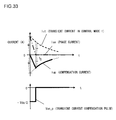
- the power conversion device may be further provided with a means for compensating transient currents generated in the AC current flowing to the motor.
- This transient current compensation means is adapted to output a compensation pulse when changeover takes place between the HM control mode and the sine wave PWM control mode.
- this transient current compensation means is adapted to output a compensation pulse when changeover takes place between the HM control mode and the sine wave PWM control mode, or, in addition thereto, when some predetermined condition is satisfied.
- the power conversion device is further provided with a decision means that makes a decision as to whether or not it is possible to detect the rotational state of the motor, and a chopper control means that, on the basis of the decision result by the decision means, outputs a predetermined signal for single phase chopper control for creating the first interval and the second interval for each of the phases, irrespective of electrical angle.
- the period of the signal for single phase chopper control is determined according to the inductance of the motor.
- a power conversion device includes a bridge circuit that includes a plurality of switching elements that make up upper and lower arms, a drive circuit that outputs drive signals for making the above described switching elements go continuous or discontinuous, and/or a controller for controlling the drive circuit; and/or, along with operating the switching elements in correspondence to the phase of the AC power that is to be converted from DC power, the continuous and discontinuous intervals of the switching elements are controlled on the basis of the modulation index.
- a harmonic component of the AC current flowing to the motor is changed to a desired value, and, when the modulation index is a maximum, square wave control is performed in which the switching elements for each phase are turned ON and OFF once each for each one rotation of the motor.
- drive signals are supplied to switching elements incorporated in the inverter circuit from a drive circuit that operates according to control signals from a control circuit for controlling the switching operation of the switching elements, and the switching elements described above perform operation to go continuous or discontinuous in correspondence to the phase of the AC power that is converted.
- the very beneficial effect is also obtained of reduction of the harmonic components of comparatively low order in the outputted AC power, such as the fifth order harmonic component and the seventh order harmonic component.
- the DC power supply here is not only limited to being a battery in which DC power is accumulated; it could also be a smoothing capacitor, for example a capacitor module 500 shown in Fig. 2 .
- this type of element may, for example, be an insulated gate bipolar transistor (hereinafter referred to as an "IGBT") or a field effect transistor (such as a MOS transistor), and this type of element is preferable from the point of view of responsiveness and controllability.
- IGBT insulated gate bipolar transistor
- MOS transistor field effect transistor
- the AC power outputted from the power conversion device described above is supplied to an inductance circuit included in a rotating electrical machine or the like, and AC current flows on the basis of its inductance operation.
- examples will be cited and explained of rotating electrical machines that perform inductance circuit operation as motors or generators. From the point of view of benefits, the use of the present invention for generating AC power to operate such a rotating electrical machine is optimum, but the present invention can also be used as a power conversion device for supplying AC power to an inductance circuit other than a rotating electrical machine.
- the switching operation of the switching elements is generated on the basis of the phase of the AC waveform that is to be outputted, while on the other hand, in a second operational region in which the rotational speed of the rotating electrical machine is lower than in the above described first operational region, the above described switching elements are controlled according to a PWM method in which the operation of the switching elements is controlled on the basis of a carrier wave of a constant frequency.
- the stopped state in which the rotor of the above described rotating electrical machine is stationary may be included in the above described second operational region.
- AC power is generated by the PWM control method as described above in the low rotational speed of the rotating electrical machine to which AC power is to be supplied, and, in a situation in which the rotational speed of the rotating electrical machine has been elevated, a transition takes place to control of generation of AC power by the HM control method as explained below.
- chopper control as described in Figs. 3 and 39 is performed in the state in which the rotating electrical machine is stopped, and a transition is executed from chopper control to PWM control.
- a transition is executed within HM control to square wave control.
- the switching timings are controlled in correspondence with the phase of the AC waveform that is to be outputted, and, as the modulation index becomes higher, the number of times that switching is performed in a half cycle of the AC power (from zero to ⁇ of electrical angle, or from ⁇ to 2 ⁇ ) gradually decreases, and finally a transition is executed to square wave control in which continuity is only established once in each half cycle.
- the embodiments described below there is the advantage that it is possible to transition smoothly to square wave control, and due to this the controllability is excellent.
- the power conversion device according to embodiments of the present invention are examples of application to power conversion devices that generate AC power for driving a rotating electrical machine in a hybrid electric vehicle (hereinafter termed an "HEV") or a pure electric vehicle (hereinafter termed an "EV").
- HEV hybrid electric vehicle
- EV pure electric vehicle
- the fundamental structure and control of a power control device for an HEV and of a power conversion device for an EV are fundamentally the same, and accordingly, as a representative example, the control structure and the circuit structure of the power conversion devices according to the following embodiments of the present invention will be explained in the case of application to an HEV, as shown in Figs. 1 and 2 .
- Fig. 1 is a figure showing control blocks of an HEV.
- the power conversion devices according to embodiments of the present invention will be explained in terms of onboard power conversion devices for an onboard electrical system that is mounted to an automobile.
- examples will be cited and explained of power conversion devices for driving a vehicle that are used in an electrical system for powering the vehicle, for which the mounting environment and the operational environment are very severe.
- a power conversion device for driving a vehicle is included in the electrical system for powering the vehicle, as a control device that drives a rotating electrical machine that powers the vehicle.
- This power conversion device for powering the vehicle converts DC power that is supplied from an onboard battery or from an onboard electricity generation device that constitutes an onboard power supply into predetermined AC power, and supplies this AC power that has been produced to the rotating electrical machine described above, thus driving that rotating electrical machine.
- the power conversion device described above not only converts DC power to AC power, but, according to the operational mode, also is capable of performing operation to convert AC power generated by the above described rotating electrical machine into DC power. This DC power thus obtained by conversion is supplied to the onboard battery.
- the structure of this embodiment is optimized for powering a vehicle such as an automobile or a truck or the like.
- the present invention may also be applied to power conversion devices of other types; for example, the present invention could also be applied to a power conversion device for a train or a ship or an aircraft or the like, to a power conversion device for use in industry for generating electric power to be supplied to a rotating electrical machine that drives a machine in a workplace, or to a power conversion device for household use that is employed as a control device for an electric motor that drives a home solar electricity generating system or an item of household electrical equipment or the like.
- an HEV 110 is a single electrically operated vehicle that is equipped with two vehicle drive systems.
- One of these is an engine system that utilizes an engine 120 as its power source.
- the engine system is used as the principal drive source for driving the HEV 110.
- the other drive system is an onboard electrical system that utilizes two motor-generators 192 and 194 as power sources.
- This onboard electrical system is principally used as a drive power source for the HEV 110 and as an electrical power generating source for the HEV 110.
- the motor-generators 192 and 194 may be, for example, synchronous machines or induction machines, and since, in terms of their method of operation, they function both as motors and as generators, in this specification they will be termed "motor-generators".
- Front wheel shafts 114 are rotatably supported at the front portion of the body of the vehicle. And a pair of front wheels 112 are provided at the ends of these front wheel shafts 114.
- Rear wheel shafts (not shown in the drawing) are rotatably supported at the rear portion of the vehicle body. And a pair of rear wheels (also not shown) are provided at the ends of these rear wheel shafts. While, with the HEV 110 of this embodiment, the so-called front wheel drive configuration is employed in which the main wheels that are powered by drive force are the front wheels 112, and the auxiliary wheels that free-wheel are the rear wheels (not shown), the present invention could also be applied to the reverse configuration, i.e. to an HEV that employs the rear wheel drive configuration.
- a front wheel side differential gear system 116 (hereinafter termed the "front wheel DEF") is provided at the central portion between the two front wheel shafts 114.
- the front wheel shafts 114 are mechanically connected to output sides of this front wheel DEF 116.
- the output shaft of a speed change mechanism 118 is mechanically connected to an input side of the front wheel DEF 116.
- the front wheel DEF 116 is a differential type drive force distribution mechanism that distributes the rotational drive force transmitted and speed-changed by the speed change mechanism 118 between the left and right front wheel shafts 114.
- the output side of the motor-generator 192 is mechanically connected to the input side of the speed change mechanism 118.
- the output side of the engine 120 and the output side of the motor-generator 194 are mechanically connected to the input side of the motor-generator 192 via a drive force distribution mechanism 122. It should be understood that the motor-generators 192 and 194 and the drive force distribution mechanism 122 are housed in the interior of the casing of the speed change mechanism 118.
- the motor-generators 192 and 194 are synchronous machines whose rotors incorporate permanent magnets. Drive control of each of the motor-generators 192 and 194 is performed by AC power that is supplied to its fixed armature winding being controlled by a respective power conversion device 140, 142.
- a battery (BAT) 136 is electrically connected to the power conversion devices 140 and 142. Accordingly mutual transfer of power can be performed between the battery 136 and the power conversion devices 140 and 142.
- the HEV 110 of this embodiment includes two grouped electric drive / generator units, i.e. a first electric drive / generator unit that includes the motor-generator 192 and the power conversion device 140, and a second electric drive / generator unit that includes the motor-generator 194 and the power conversion device 142; and usage is divided between these according to the current operational state.
- a first electric drive / generator unit that includes the motor-generator 192 and the power conversion device 140
- a second electric drive / generator unit that includes the motor-generator 194 and the power conversion device 142
- usage is divided between these according to the current operational state.
- the first electric drive / generator unit is operated as an electricity generation unit by the rotational force from the engine 120, while the second electric drive / generator unit is operated as an electrical drive unit using the power that is generated in this way.
- the first electric drive / generator unit it is possible to operate the first electric drive / generator unit as an electrical drive unit using the power of the battery 136, so as to drive the vehicle only with the drive force of the motor-generator 192. Yet further, with this first embodiment, it is possible to operate either the first electric drive / generator unit or the second electric drive / generator unit as an electricity generation unit with power from the engine 120, or with power from the vehicle wheels, so as to charge up the battery 136.
- the battery 136 is also used as a power supply for driving an auxiliary machinery motor 195.
- auxiliary machinery there may be incorporated, for example, a motor that drives a compressor for an air conditioner, or a motor that drives a hydraulic pump for control.
- DC power is supplied from the battery 136 to the power conversion device 43, and is converted into AC power by the power conversion device 43 and supplied to the motor 195.
- This auxiliary machinery power conversion device 43 is endowed with a function similar to that of the power conversion devices 140 and 142 for driving the vehicle, and controls the phase, the frequency, and the power of the AC that it supplies to the motor 195.
- the motor 195 generates torque due to the supply of AC power that has a phase leading with respect to the rotation of the rotor of the motor 195.
- the motor 195 operates as a generator, so that the motor 195 performs regenerative braking operation.
- the control function of this type for the power conversion device 43 is the same as the control functions for the power conversion devices 140 and 142.
- the maximum conversion power of the power conversion device 43 is smaller than those of the power conversion devices 140 and 142 since the capacity of the motor 195 is smaller than the capacities of the motor-generators 192 and 194.
- the circuit structure and the operations of the power conversion device 43 are fundamentally the same as the circuit structures and the operations of the power conversion devices 140 and 142.
- a capacitor module 500 is in close electrical relationship with the power conversion devices 140, 142 and 43. Moreover, these devices all have the common feature of needing countermeasures against generation of heat. Yet further, it is desirable to make the volumes of the power conversion devices as small as possible. From these points of view, in the power conversion device that is described in detail hereinafter, the power conversion devices 140 and 142, the power conversion device 43, and the capacitor module 500 are housed within the chassis of the power conversion device. With this type of structure, it is possible to implement a system that is compact and whose reliability is high.
- the beneficial effect is obtained that it is possible to simplify the wiring and to implement countermeasures against noise. Yet further, it is possible to reduce the inductances in the circuitry that connects the capacitor module 500, the power conversion devices 140 and 142, and the power conversion device 43, and due to this not only is it possible to prevent the generation of spike voltages, but also it is possible to anticipate reduction of heat generation and enhancement of heat dissipation efficiency.
- each of the power conversion devices 140, 142, and 43 has its own individual structure.
- each of the power conversion devices 140, 142, and 43 has similar circuit structure and operates in a similar manner and has similar functions. Accordingly here the power conversion device 140 will be explained as a representative example.
- the power conversion device 200 includes the power conversion device 140 and the capacitor module 500.
- the power conversion device 140 includes a power switching circuit 144 and a control unit 170.
- the power switching circuit 144 includes a plurality of switching elements that operate as upper arms and a plurality of switching elements that operate as lower arms.
- IGBTs Insulated Gate Bipolar Transistor
- the IGBTs 328 that operate as upper arms are connected in parallel with diodes 156, while the IGBTs 330 that operate as lower arms are connected in parallel with diodes 166.
- An intermediate point (i.e. an intermediate electrode) 169 of each of a plurality of upper and lower arm series circuits 150 in the example shown in Fig.
- the control unit 170 also includes a driver circuit 174 that controls the operation of the power switching circuit 144, and a control circuit 172 that supplies a control signal to the driver circuit 174 via a signal line 176.
- the IGBTs 328 and 330 in the upper and lower arms are switching elements, and are operated by drive signals received from the control unit 170 so as to convert DC power supplied from the battery 136 into three phase AC power. This power that has been converted is supplied to the armature windings of the motor-generator 192. As described above, the power conversion device 140 is capable of converting the three phase AC power generated by the motor-generator 192 into DC power.
- the power conversion device 200 incorporates, as shown in Fig. 1 , not only the power conversion devices 140 and 142, but also the power conversion device 43 and the capacitor module 500. Since, as described above, the power conversion devices 140 and 142 and also the power conversion device 43 have similar structures, here the power conversion device 140 will be described as a representative, and description of the power conversion device 142 and the power conversion device 43 will be omitted since it will already have been described.
- the power switching circuit 144 is built as a three phase bridge circuit.
- a DC positive terminal 314 and a DC negative terminal 316 are respectively electrically connected to the positive electrode side and the negative electrode side of the battery 136.
- the upper and lower arm series circuits 150, 150, 150 for each of the three phases are electrically connected in parallel between the DC positive terminal 314 and the DC negative terminal 316.
- the upper and lower arm series circuits 150 will be termed "arms".
- Each of these arms includes an upper arm side switching element 328 and a diode 156, and a lower arm side switching element 330 and a diode 166.
- the IGBTs 328 and 330 are used as the switching elements.
- the IGBTs 328 and 330 have respective collector electrodes 153 and 163, emitter electrodes (respective signal emitter electrode terminals) 155 and 165, and gate electrodes (respective gate electrode terminals) 154 and 164.
- Diodes 156 and 166 are respectively electrically connected in parallel between the collector electrodes 153 and 163 of the IGBTs 328 and 330 and their emitter electrodes, as shown in the figure.
- Each of the diodes 156 and 166 has two electrodes, a cathode electrode and an anode electrode.
- the cathode electrodes are electrically connected to the collector electrodes of the IGBTs 328 and 330 while the anode electrodes are electrically connected to the emitter electrodes of the IGBTs 328 and 330, so that the forward directions of the diodes 156 and 166 are in the directions from the emitter electrodes of the IGBTs 328 and 330 towards their collector electrodes. It would also be acceptable to use MOSFETs (Metal Oxide Semiconductor Field Effect Transistors) as these switching elements. In such a case, the diodes 156 and 166 would not be required.
- the upper and lower arm series circuits 150 are provided for each of three phases, corresponding to each of the phases of the AC power supplied to the three phase motor-generator 192, and the connection points 169 between the emitter electrodes of the IGBTs 328 and the collector electrodes of the IGBTs 330 are used for outputting the U phase, the V phase, and the W phase of the AC power.
- connection points 169 described above for each of the three phases are connected to the armature windings of the motor-generator 192 (in the case of a synchronous electric motor, the stator windings) for the U phase, the V phase, and the W phase, and thereby currents for the U phase, the V phase, and the W phase flow in the above described armature windings.
- the upper and lower arm series circuits 150 are connected in parallel.
- the collector electrodes 153 of the upper arm IGBTs 328 are each electrically connected via DC bus bars or the like to the positive pole side capacitor electrodes of the capacitor module 500 via the positive terminals 157 (i.e. the P terminals), while the emitter electrodes of the lower arm IGBTs 330 are each electrically connected to the negative pole side capacitor electrode of the capacitor module 500 via the negative terminals 158 (i.e. the N terminals).
- the capacitor module 500 acts as a smoothing circuit for suppressing fluctuations of the DC voltage generated by the switching operation of the IGBTs 328 and 330.
- the positive pole side of the battery 136 is connected to the positive pole side capacitor electrode of the capacitor module 500, while the negative pole side of the battery 136 is connected to the negative pole side capacitor electrode of the capacitor module 500. Due to this, the capacitor module 500 is connected between the collector electrodes 153 of the upper arm IGBTs 328 and the positive electrode side of the battery 136, and between the emitter electrodes of the lower arm IGBTs 330 and the negative pole side of the battery 136, so as to be electrically connected to the battery 136 and to the upper and lower arm series circuits 150 in parallel.
- the control unit 170 performs control for operating the IGBTs 328 and 330 to make them continuous and discontinuous, and includes a control circuit 172 that generates timing signals for controlling the timings at which the IGBTs 328 and 330 are switched on the basis of information that is inputted from other control devices or sensors or the like, and a drive circuit 174 that generates drive signals for causing this switching operation of the IGBTs 328 and 330 on the basis of these timing signals output from the control circuit 172.
- the control circuit 172 includes a microcomputer that performs processing for calculating the switching timings for the IGBTs 328 and 330.
- a target torque value that is requested for the motor-generator 192, values of the currents being supplied to the armature windings of the motor-generator 192 from the upper and lower arm series circuits 150, and the position of the magnetic poles of the rotor of the motor-generator 192, are input to this microcomputer.
- the target torque value is a value based upon a command signal output from a higher level control device not shown in the figures.
- the current values are values that are determined on the basis of detection signals output from a current sensor 180.
- the magnetic pole position is a value that is determined on the basis of a detection signal output from a magnetic pole rotation sensor not shown in the figures that is provided to the motor-generator 192. While in this embodiment an example is described in which the AC current value for each of the three phases is detected, it would also be acceptable to arrange to detect AC current values for only two of the phases.
- the microcomputer incorporated in the control circuit 172 calculates current command values for the d and q axes of the motor-generator 192 on the basis of the target torque value, and then calculates voltage command values for the d and q axes on the basis of the differences between the current command values for the d and q axes that are the result of the above calculation and the current values for the d and q axes that have been detected, and generates drive signals in pulse form from these voltage command values for the d and q axes.
- the control circuit 172 has the function of generating drive signals according to two different methods. One or the other of these two methods is selected, on the basis of the state of the motor-generator 192, i.e. its inductance load, or on the basis of the frequency of the AC power to which it is desired to perform conversion, or the like.
- One of the two methods described above is a modulation method (hereinafter referred to as the HM method) in which the switching operation of the IGBTs 328 and 330, that are the switching elements, is controlled on the basis of phase of the AC waveform that it is desired to output.
- the other of the two methods described above is the per se known PWM (Pulse Width Modulation) method.
- the driver circuit 174 When driving a lower arm, the driver circuit 174 amplifies the modulated pulse signal and outputs it as a drive signal to the gate electrode of the IGBT 330 of the corresponding lower arm. Furthermore, when driving an upper arm, it amplifies the modulated pulse signal after having shifted the level of the reference potential of this modulated pulse signal to the level of the reference potential of the upper arm, and outputs it as a drive signal to the gate electrode of the IGBT 328 of the corresponding upper arm. Due to this, each of the IGBTs 328 and 330 performs switching operation on the basis of the drive signal that is inputted to it.
- the power conversion device 140 converts the voltage that is supplied from the battery 136, which constitutes a DC power supply, into output voltages for the U phase, the V phase, and the W phase spaced apart by 2 ⁇ /3 radians of electrical angle, and supplies these output voltages to the motor-generator 192, which is a three phase AC motor.
- the electrical angle is a quantity that corresponds to the rotational state of the motor generator 192, i.e. in concrete terms to the rotational position of its rotor, and is a cyclic quantity that varies between 0 and 2 ⁇ .
- this electrical angle As a parameter, it is possible to determine the switching states of the IGBTs 328 and 330, in other words the output voltages for the U phase, the V phase, and the W phase, according to the rotational state of the motor-generator 192.
- control unit 170 performs detection of anomalies such as excess current, excess voltage, excess temperature and so on, and thereby protects the upper and lower arm series circuits 150.
- sensing information is inputted to the control unit 170.
- information about the current that flows to the emitter electrode of each of the IGBTs 328 and 330 is inputted from the signal emission electrode terminals 155 and 165 of each arm to the corresponding drive unit (IC).
- each of the drive units (ICs) performs excess current detection, and, if it has detected excess current, stops the switching operation of the corresponding IGBT 328 or 330, thus protecting the corresponding IGBT 328 or 330 from excessive current.
- information about the temperatures of the upper and lower arm series circuits 150 is inputted to the microcomputer from temperature sensors (not shown in the figures) that are provided to the upper and lower arm series circuits 150.
- information about the voltages at the DC positive electrode sides of the upper and lower arm series circuits 150 is inputted to the microcomputer.
- the microcomputer performs excess temperature detection and excess voltage detection on the basis of this information, and, if it detects excess temperature or excess voltage, stops the switching operation of all of the IGBTs 328 and 330, thus protecting the upper and lower arm series circuits 150 (and also the semiconductor modules that include these circuits 150) from excess temperature and excess voltage.
- the upper and lower arm series circuits 150 are series circuits of the upper arm IGBTs 328 and the upper arm diodes 156, and series circuits of the lower arm IGBTs 330 and the lower arm diodes 166.
- the IGBTs 328 and 330 are switching semiconductor devices. The operation of the IGBTs 328 and 330 of the upper and lower arms of the power conversion device circuit 144 to go continuous and discontinuous is changed over in a fixed order. And the current in the stator windings of the motor-generator 192 during this changeover flows in the circuits constituted by the diodes 156 and 166.
- the upper and lower arm series circuits 150 have: positive terminals (P terminals) 157, negative terminals (N terminals) 158, AC terminals 159 from the connection points 169 of the upper and lower arms, upper arm signal terminals (signal emission electrode terminals) 155, upper arm gate electrode terminals 154, lower arm signal terminals (signal emission electrode terminals) 165, and lower arm gate electrode terminals 164.
- the power conversion device 200 has the DC connector 138 at its input side and the AC connector 188 at its output side, and is connected to the battery 136 and the motor-generator 192 via these two connectors 138 and 188, respectively.
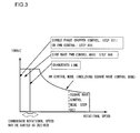
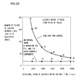
- Fig. 3 is a graph showing the relationship between the maximum torque that can be outputted by the rotating electrical machine and the rotational speed of the rotating electrical machine.
- the changing over between the control modes that is performed by the power conversion device 140 will now be explained with reference to this Fig. 3 .
- the power conversion device 140 employs either the PWM control method or the HM control method that will be described hereinafter, while changing over between them according to the rotational speed of the motor-generator 192, or according to the frequency of the AC power to be outputted.
- Fig. 3 shows the way in which the power conversion device 140 changes over between these control methods. It should be understood that the rotational speed at which changeover between the control methods is performed may be varied as desired.
- the rotational speed at which the motor-generator is changed over between control according to the PWM method and control according to the HM method is not to be considered as being particularly limited; for example, it may be considered to perform control according to the PWM method at rotational speeds less than or equal to 700 rpm, while performing control according to the HM method at rotational speeds higher than 700 rpm.
- the range from 1500 rpm to 5000 rpm is an operational region in which control according to the HM method is particularly appropriate, and, in this region, the beneficial effect obtained for reduction of switching losses in the switching elements by employing the HM method as contrasted to using the PWM method is very great.
- this operational region is an operational region that is much used for traveling in urban areas, and control according to the HM method provides a great beneficial effect in this operational region that is closely related to our daily lives.
- the mode of control according to the PWM control method (hereinafter termed the "PWM control mode) is used in the region in which the rotational speed of the motor-generator 192 is comparatively low, while on the other hand the mode of control according to the HM control method that will be described hereinafter is used in the region in which the rotational speed is comparatively high.
- the power conversion device 140 performs control using a PWM signal.
- voltage command values for the d and q axes of the motor-generator 192 are calculated by the microcomputer within the control circuit 172 on the basis of the target torque value that is inputted, and these are converted to voltage command values for the U phase, the V phase, and the W phase.
- a sine wave corresponding to the voltage command value is taken as a fundamental wave, this is compared with a triangular wave of a predetermined period that constitutes a carrier wave, and a modulated wave in pulse form having a pulse width determined on the basis of the result of this comparison is outputted to the driver circuit 174.
- the driver circuit 174 by outputting a drive signal corresponding to this modulated wave from the driver circuit 174 to the IGBTs 328 and 330 that correspond respectively to the upper and lower arms of each phase, the DC voltage outputted from the battery 136 is converted into three phase AC voltage, and is supplied to the motor-generator 192.
- HM control The details of HM control will be explained hereinafter.
- the modulated waves generated by the control circuit 172 in the HM control mode are outputted to the driver circuit 174. Due to this, drive signals corresponding to these modulated waves are outputted from the driver circuit 174 to the IGBTs 328 and 330 that correspond to each of the phases. As a result, the DC voltage outputted from the battery 136 is converted into three phase AC voltage, and is supplied to the motor-generator 192.
- control is performed by changing over between the PWM control mode and the HM control mode as described above according to the frequency of the AC power to which conversion is desired or according to the rotational speed of the motor that is correlated with this frequency; in other words the HM control method is applied in the high rotational speed region in which it is unlikely that serious influence will be experienced from the low order harmonic components, while the PWM control method is applied in the low rotational speed region in which it is quite likely for torque pulsations to be generated.
- the HM control method is applied in the high rotational speed region in which it is unlikely that serious influence will be experienced from the low order harmonic components
- the PWM control method is applied in the low rotational speed region in which it is quite likely for torque pulsations to be generated.
- the state of control of the motor for which the number of times of switching per unit time or per unit cycle of the AC power that is outputted becomes a minimum is the state in which control is performed by square waves, in which the switching elements for each of the phases are turned ON and OFF once per each half cycle of the AC power supplied to the motor.
- This state of control by square waves may, in the HM control method described above, be considered as being the final state reached by reduction of the number of times of switching per half cycle according to increase of the modulation index of the AC power waveform that is converted, and thus as being one type of state of control by the HM control method. This point will be explained in detail hereinafter.
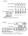
- Figs. 5A and 5B An example of the harmonic components in the generated AC power is shown in Figs. 5A and 5B.
- Fig. 5A is an example in which an AC waveform that varies in a square wave pattern has been decomposed into a sine wave (this is the fundamental wave) and harmonics of the fifth order, the seventh order, the eleventh order, .... and so on.
- Equation (1) shows that the square wave shown in Fig. 5A is made up from the fundamental sine wave given by 4/ ⁇ sin( ⁇ t) and components of the third order, the fifth order, the seventh order... and so on, that are its harmonic components. It will be understood that, by combining higher order harmonic components with the fundamental wave in this manner, the result can be made to approach arbitrarily close to a square wave.
- Fig. 5B shows the situation when the amplitudes of the fundamental wave, the third order harmonic component, and the fifth order harmonic component are compared together. If the amplitude of the square wave of Fig. 5A is taken as unity, then the amplitude of the fundamental wave is 1.27, the amplitude of the third order harmonic component is 0.42, and the amplitude of the fifth order harmonic component is 0.25. Since the amplitude of each harmonic component becomes smaller in this manner as its order becomes higher, it will be understood that the influence that it exerts upon square wave control also becomes smaller. In particular in connection with the influence of the various harmonic components upon a rotating electrical machine, the influence of the fifth order harmonic component is large because it is of relatively low order.
- HM control In consideration of torque pulsations that may be generated when the switching elements are made continuous and discontinuous according to a square wave pattern, by leaving those higher order harmonic components whose influence is small and ignoring their influence, while eliminating those lower order harmonic components whose influence is large, it is possible to implement a power converter that can reduce switching losses and moreover can keep the increase of torque pulsations to a low level.
- AC power is outputted in which the harmonic components included in square wave AC current are more or less reduced according to the state of control, and by doing this the influence of torque pulsations upon the motor control is reduced, while on the other hand it is arranged to reduce the switching losses by allowing certain harmonic components to be included within a range for which no problem actually arises in practice.
- this type of control method is referred to as the HM control method.
- the PWM control method in a state in which, with the HM control method, AC power of low frequency would be outputted in which the influence of harmonic components would be large, or that would provide poor controllability.
- control circuit 172 for implementing the control described above.
- Methods of three different types for motor control will be explained as control methods performed by this control circuit 172 provided to the power conversion device 140, and, in the following, these three methods for motor control will be explained in connection with first, second, and third embodiments of the present invention.
- the fundamental operation of the control circuit is performed in software by processing by a microcomputer that operates according to a control program, but, for the convenience of explanation and understanding, the operation of the microcomputer will be considered as being separated into functional blocks, and the explanation will be made in terms of the actual hardware existence of circuit blocks corresponding to these functions, that in fact would be an alternative possibility for implementation.
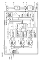
- a block diagram in which the functions of the motor control system employing this control circuit 172 according to the first embodiment of the present invention are shown as functional blocks is given in Fig. 6 .
- a control command for the motor-generator 192 for example a torque command T* that provides a target torque value, is inputted to the control circuit 172 by a higher level control device that controls the vehicle.
- a torque command to current command converter 410 converts a torque command to a d axis current command signal Id* and a q axis current command signal Iq* on the basis of this torque command T* that has been inputted and rotational speed information according to a magnetic pole position signal ⁇ detected by a magnetic pole rotation sensor 193.
- the d axis current command signal Id* and the q axis current command signal Iq* thus produced by the torque command to current command converter 410 are respectively outputted to current controllers (ACRs) 420 and 421.
- the current controllers (ACRs) 420 and 421 respectively calculate a d axis voltage command signal Vd* and a q axis voltage command signal Vq*, so that the currents flowing to the motor-generator 192 track the d axis current command signal Id* and the q axis current command signal Iq*
- the pulse modulator 430 for HM control includes a voltage phase difference calculator 431, a modulation index calculator 432, and a pulse generator 434.
- the d axis voltage command signal Vd* and the q axis voltage command signal Vq* outputted from the current controller 420 are inputted to the voltage phase difference calculator 431 and the modulation index calculator 432 in the pulse modulator 430.
- the modulation index calculator 432 calculates the modulation index by normalizing the magnitude of the vector given by the d axis voltage command signal Vd* and the q axis voltage command signal Vq* by the voltage of the battery 136, and outputs a modulation index signal a corresponding to this modulation index to the pulse generator 434.
- the modulation index signal a described above is determined on the basis of the battery voltage supplied to the power switching circuit 144 shown in Fig. 2 , i.e. the DC voltage, and, when the battery voltage becomes higher, this modulation index a has a tendency to become smaller. Moreover, when the amplitude value of the command value becomes high, the modulation index a has a tendency to become high.
- the pulse generator 434 On the basis of the voltage phase signal ⁇ v from the voltage phase difference calculator 431 and the modulation index signal a from the modulation index calculator 432, the pulse generator 434 generates six pulse signals based upon HM control corresponding to the upper and lower arms in the inverter circuit for the U phase, the V phase, and the W phase. And these pulse signals that have been generated are outputted to the changeover device 450, and (when the changeover device 450 is switched over to them) are outputted from the changeover device 450 to the driver circuit 174 (as explained with reference to Fig. 2 ), and based thereupon drive signals are generated and outputted to the switching elements included in the inverter circuit.
- HM pulse signals the method by which the pulse signals are generated on the basis of HM control
- the pulse modulator 440 for PWM control generates six pulse signals based upon PWM control (hereinafter termed "PWM pulse signals") corresponding to the upper and lower arms in the inverter circuit for the U phase, the V phase, and the W phase on the basis of the d axis voltage command signal Vd* and the q axis voltage command signal Vq* outputted from the current controller 421, and on the basis of the magnetic pole position signal ⁇ from the magnetic pole rotation sensor 193.
- PWM pulse signals that have been generated are outputted to the changeover device 450 and (when the changeover device 450 is switched over to them) are supplied from the changeover device 450 to the driver circuit 174 (as explained with reference to Fig. 2 ), and based thereupon drive signals are generated and outputted to the switching elements included in the inverter circuit.
- the changeover device 450 selects either the HM pulse signals outputted from the pulse modulator 430 for HM control or the PWM pulse signals outputted from the pulse modulator 440 for PWM control. This selection of pulse signals by the changeover device 450 is performed according to the rotational speed of the motor-generator 192, as previously described. In other words, if the rotational speed of the motor-generator 192 is less than a predetermined threshold value that has been set as a changeover line, then the PWM control method is applied by the power conversion device 140 by the PWM pulse signals being selected.
- the HM control method is applied by the power conversion device 140 by the HM pulse signals being selected. In this manner, either the HM pulse signals or the PWM pulse signals are selected by the changeover device 450, and are outputted to the driver circuit 174.
- either the HM pulse signals or the PWM pulse signals are outputted from the control circuit 172 to the driver circuit 174 as modulated waves.
- drive signals are outputted by the driver circuit 174 to the IGBTs 328 and 330 of the power switching circuit 144.
- the control circuit 172 has been expressed in the form of a block diagram, in which functions that actually are performed by a microcomputer that executes a computer program are described as being separate blocks.
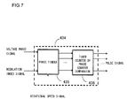
- This pulse generator 434 is implemented by a phase finder 435 and a timer counter comparator 436, as shown for example in Fig. 6 .
- the phase finder 435 searches for switching pulse phases in a table of phase information that has been stored in advance, extracts the phases of the switching pulses that are to be outputted for each of the upper and lower arms for the U phase, the V phase, and the W phase, and outputs information specifying the results that have been found to the timer counter comparator 436.
- the timer counter comparator 436 generates HM pulse signals as switching commands for each of the upper and lower arms for each of the U phase, the V phase, and the W phase. These six HM pulse signals for each of the upper and lower arms of each of the phases thus generated by the timer counter comparator 436 are outputted to the changeover device 450, as previously described.
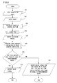
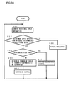
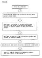
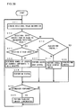
- Fig. 8 is a flow chart for explanation of the details of this procedure for pulse generation by the phase finder 435 and the timer counter comparator 436 of Fig. 7 .
- the phase finder 435 inputs the modulation index a as an input signal, and then in a step 802 it inputs the voltage phase signal ⁇ v as an input signal.
- the phase finder 435 calculates a range of voltage phase that corresponds to the next control cycle, on the basis of the current voltage phase signal ⁇ v that has been inputted, and in consideration of the control delay time period and the rotational speed.
- the phase finder 435 performs lookup from the ROM.
- the phases for ON and OFF switching are found for the range of voltage phase calculated in the step 803, according to a table that has been stored in advance in a ROM (not shown in the figures).
- the phase finder 435 outputs to the timer counter comparator 436 the information specifying the phases for switching ON and OFF that has been found by the ROM lookup in the step 804.
- the timer counter comparator 436 converts this phase information into time period information in a step 806, and generates HM pulse signals using a compare and match function with a timer counter. It should be understood that the process of converting the phase information to time period information utilizes the information in the rotational speed signal. Or, in the step 806, it would also be acceptable to generate the HM pulses by using a compare and match function with a phase counter for the information for the phases for switching ON and OFF obtained by ROM lookup in the step 804.
- the timer counter comparator 436 outputs the HM pulse signals generated in the step 806 to the changeover device 450.
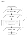
- the HM pulse signals are generated by the pulse generator 434.
- a step 801 the pulse generator 434 inputs the modulation index signal a, and then in a step 802 it inputs the voltage phase signal ⁇ v.
- the pulse generator 434 determines the phases for switching ON and OFF for each control cycle of the current controller (ACR) by calculation, on the basis of the modulation index signal a and the voltage phase signal ⁇ v that have thus been inputted, and in consideration of the control delay time period and the rotational speed.
- the pulse generator 434 designates the orders of the harmonic components to be eliminated. For this, in the next step 822 the pulse generator 434 performs processing such as matrix calculation or the like according to the orders of the harmonic components that have been designated, and outputs pulse reference angles in the step 823.
- the pulse generator 434 performs the following matrix calculation in the next step 822.
- Equation (5) a row vector like that shown in Equation (5) is constructed for the harmonic components of the third order, the fifth order, and the seventh order that are to be eliminated.
- x 1 x 2 x 3 ⁇ / 2 k 1 / 3 k 2 / 5 k 3 / 7
- k 1 /3, k 2 /5, and k 3 /7 The elements within the right side brackets of Equation (5) are k 1 /3, k 2 /5, and k 3 /7.
- k 1 , k 2 , and k 3 may be selected to be any desired odd numbers.
- k 1 is never selected to be 3, 9, or 15, k 2 is never selected to be 5, 15, or 25, k 3 is never selected to be 7, 21 35, and so on. Under these conditions, the harmonic components of the third order, the fifth order, and the seventh order are perfectly eliminated.
- the value of each of the terms in Equation (5) may be determined by making the value of the denominator be the order of a harmonic component that is to be eliminated, and by making the value of the numerator be any desired odd number except for an odd multiple of the denominator.
- the number of elements in the row vector is 3, because there are harmonic components of three orders to be eliminated (i.e. the third order, the fifth order, and the seventh order).
- Equation (5) a vector with N elements whose values are determined by combinations of a denominator and a numerator, in other words a vector of N columns, may be set up.
- this N column vector will be termed the "harmonic component reference phase vector".
- Equation (6) is calculated by transposing this harmonic component reference phase vector.
- the pulse reference angles S 1 through S4 are obtained.
- pulse reference angles S 1 through S4 are parameters that specify the center positions of the pulses, and are compared with a triangular wave carrier that will be described hereinafter. If in this manner the number of pulse reference angles (S1 through S4) is four, then, generally, the number of pulses for one cycle of the voltages between lines will be 16.
- S 1 S 2 S 3 S 4 2 1 0 0 1 0 1 1 1 0 1 1 1 - 1 1 1 1 1 1 1 1 1 1 1 1 1 1 ⁇ x 1 x 2 x 3
- the pulse reference angle outputs S1 through S8 are obtained.
- the number of pulses for one cycle of the voltages between lines is 32.
- the relationship between the number of harmonic components to be eliminated and the number of pulses is generally as follows. That is: if there are two harmonic components to be eliminated, then the number of pulses for one cycle of the voltages between lines is 8; if there are three harmonic components to be eliminated, then the number of pulses for one cycle of the voltages between lines is 16; if there are four harmonic components to be eliminated, then the number of pulses for one cycle of the voltages between lines is 32; and if there are five harmonic components to be eliminated, then the number of pulses for one cycle of the voltages between lines is 64. In a similar manner, each time the number of harmonic components to be eliminated increases by one, the number of pulses for one cycle of the voltages between lines doubles.
- Pulse waveforms for the three voltages between lines i.e. for the voltage between the U and V lines, the voltage between the V and W lines, and the voltage between the W and U lines, are created by the HM pulse signals that are generated as described above by the pulse generator 434.
- These pulse waveforms of the voltages between lines are all actually the same pulse waveform, but shifted apart by 2 ⁇ /3. Accordingly in the following only the voltage between the U and V lines will be explained, since it will serve as a representative of all of the voltages between lines.
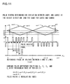
- One method of implementing this is an algorithm for comparing the center phases of the pulses of the voltage between the U and V lines in the range 0 ⁇ ⁇ uv1 ⁇ ⁇ /2 with a four channel phase counter, and for generating the pulses of the voltages between the U and V lines for a full cycle, in other words for the range 0 ⁇ ⁇ uv1 ⁇ 2 ⁇ , on the basis of the result of this comparison.
- a conceptual figure for this is shown in Fig. 11 .
- Fig. 11 shows, as an example, a case in which the number of pulses of the voltage between lines in the range 0 ⁇ ⁇ uv1: ⁇ /2 is 4.
- the pulse reference angles S1 through S4 are the center phases of these four pulses.
- Each of carr1( ⁇ uv1), carr2( ⁇ uv1), carr3( ⁇ uv1), and carr4( ⁇ uv1) represents one of four phase counters on four channels. All of these phase counters are triangular waves having a period of 2 ⁇ radians with respect to the reference phase ⁇ uvl. Moreover, carr1( ⁇ uv1) and carr2( ⁇ uv1) are deviated apart by a deviation d ⁇ in the amplitude direction, and the same relationship holds for carr3( ⁇ uv1) and carr4( ⁇ uv1).
- d ⁇ denotes the width of the pulses of the voltage between lines.
- the amplitude of the fundamental wave changes linearly with respect to this pulse width d ⁇ .
- the pulses of the voltage between lines are formed at each point of intersection of the phase counters carr1( ⁇ uvl), carr2( ⁇ uvl), carr3( ⁇ uvl), and carr4( ⁇ uvl) and the pulse reference angles S 1 through S4 that give the center phases of the pulses in the range 0 ⁇ ⁇ uv1 ⁇ ⁇ /2. Due to this, the pulse signals are formed in a pattern that is symmetrical every 90°.
- pulses of width d ⁇ and having a positive amplitude are generated at the points that carr1( ⁇ uv1) and carr2( ⁇ uv1) and S1 through S4 agree with one another.
- pulses of width d ⁇ and having a negative amplitude are generated at the points that carr3( ⁇ uv1) and carr4( ⁇ uv1) and S1 through S4 agree with one another.
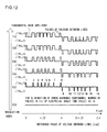
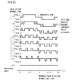
- Fig. 12 Examples of waveforms of the voltage between lines generated for various modulation indices using a method like that explained above are shown in Fig. 12 .
- the pulse width increases almost proportionally to increase of the modulation index. By increasing the pulse width in this manner, it is possible to increase the effective value of the voltage.
- switching operation is performed on the basis of the AC power that is required to be outputted from the various switching elements of the power switching circuit 144 by the drive signals from the driver circuit 174 being supplied to the switching elements.
- the number of times that the switching elements are switched for each one cycle of the AC power has a tendency to increase along with increase of the types of harmonic components that are to be eliminated.
- the harmonic components whose order is a multiple of three act to mutually cancel one another out, accordingly it will be acceptable not to include these harmonic components as ones that are to be eliminated.
- the modulation index increases when the voltage of the DC power that is supplied decreases, and there is a tendency for the continuous intervals in which the switching operation goes to continuous to become longer. Furthermore, when driving a rotating electrical machine such as a motor or the like, if the torque to be generated by the rotating electrical machine becomes larger, then the modulation index becomes larger, and as a result the continuous intervals of the switching operation become longer; while, if the torque to be generated by the rotating electrical machine becomes smaller, then the continuous intervals of the switching operation become shorter.
- the power switching circuit 144 is controlled according to the PWM method at least at the stage in which the vehicle is being started off from rest in the stationary state, and the control method is changed over to the HM method after the vehicle has accelerated somewhat.
- the control method is changed over to the HM method after the vehicle has accelerated somewhat.
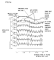
- the modulation index when the modulation index is fixed as described above, the specific characteristic is exhibited that the waveform of the voltage between lines consists of a train of pulses of equal widths, except for certain exceptions. It should be understood that, when exceptionally the widths of some pulses of the voltage between lines are not equal to the widths of the other pulses in the pulse train, this is because, as described above, a pulse that has positive amplitude and a pulse that has negative amplitude have become overlapped. In this case, if the portion where the pulses are overlapped is decomposed into the pulse that has positive amplitude and the pulse that has negative amplitude, then the widths of all of the pulses over the entire cycle necessarily become equal. In other words, the modulation index changes along with change of the pulse widths.
- a pulse waveform of the voltage between lines due to an HM pulse signal generated according to the present invention is shown in Fig. 14 .
- the modulation index increases when the target torque or the target rotational speed, i.e. the command value of the motor-generator, increases.
- a pulse is meant a continuous interval of the inverter circuit, during which a current is supplied from the DC power supply to the load such as a rotating electric machine or the like. It will be understood that, when in Fig. 15 the modulation index becomes 1.17 or greater, the gap between two adjacent pulses disappears, in a similar manner to the case in Fig. 14 . It should be understood that there is a phase difference of ⁇ /6 between the phase voltage pulse waveform shown in Fig. 15 and the pulse waveform of the voltage between lines shown in Fig. 14 .
- the discontinuous interval of the inverter circuit becomes shorter.
- the discontinuous interval of the inverter circuit becomes short, and it becomes impossible for the switching elements incorporated in the inverter circuit to perform their interception operation so quickly. In this case, their continuous operation is continued without interruption. Due to this, the number of intercepted intervals in a half cycle decreases as the modulation index becomes high, and finally the system operates in a rectangular wave control mode in which it goes continuous just once in a full half cycle.
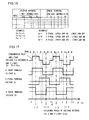
- Fig. 16 there is shown an example of a conversion table that is employed for converting the pulses of the voltage between lines to phase voltage pulses.
- the six modes 1 through 6 listed in the column at the left end of this table are numbers allocated to the switching state that currently is in force.
- the relationships from the voltages between lines to the output voltages are one-to-one with the modes #1 through #6.
- Each mode is an active interval in which energy transfer takes place between the DC side and the three phase AC side. It should be understood that the voltages between lines of Fig. 16 have been adjusted by normalizing the patterns exhibited as potential differences between the different phases by the battery voltage Vdc.
- the table of Fig. 16 is stored in a memory, and shows the phases that are used for control and the pulses between lines, in other words, the phases and the states of continuity between lines.
- the phase terminal voltages at this time that are proportional to the gate voltages), according to the table of Fig.
- Vu ⁇ 1 the upper arm of the U phase is ON and the lower arm is OFF
- Vv ⁇ 0 the upper arm of the V phase is OFF and the lower arm is ON
- Vw ⁇ 0 the upper arm of the W phase is OFF and the lower arm is ON.
- FIG. 17 An example of conversion of pulses of a voltage between lines to phase voltage pulses using the conversion table of Fig. 16 in the case in which the power switching circuit 144 is being controlled in the square wave mode is shown in Fig. 17 .
- the upper portion shows the voltage Vuv between the U and V lines as a representative example of a voltage between lines, while the lower portion shows the corresponding U phase terminal voltage Vu, the corresponding V phase terminal voltage Vv, and the corresponding W phase terminal voltage Vw.
- the mode shown in the conversion table of Fig. 16 changes in order from 1 to 6. It should be understood that no three phase short circuited interval as described hereinafter exists in the square wave control mode.
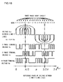
- Fig. 18 shows the situation when conversion of the pulse waveform of the voltage between lines shown in the example of Fig. 12 into phase voltage pulses is performed according to the conversion table of Fig. 16 .
- the upper portion of this figure shows the pulses of the voltage between the U and the V lines as a representative example of the voltages between lines, while the lower portion shows the U phase terminal voltage Vu, the V phase terminal voltage Vv, and the W phase terminal voltage Vw.
- the number of the mode i.e. the active interval in which energy transfer takes place between the DC side and the three phase AC side
- the time interval over which a three phase short circuit is created are shown in the upper portion of Fig. 18 .
- this three phase short circuit interval while either all of the upper arms for all of the three phases are ON or all of the lower arms for all of the three phases are ON, any of the switch modes may be selected, according to the situation with switching losses and continuity losses.
- the U phase terminal voltage Vu is 1 and the V phase terminal voltage Vv is 0 (modes #1 and #6).
- the U phase terminal voltage Vu and the V phase terminal voltage Vv have the same value, in other words either Vu is 1 and moreover Vv is 1 (mode #2, three phase short circuit), or Vu is 0 and moreover Vv is 0 (mode #5, three phase short circuit).
- the voltage Vuv between the U and V lines is -1
- the U phase terminal voltage Vu is 0 and the V phase terminal voltage Vv is 1 (modes #3 and #4).
- the phase terminal voltage pulses i.e. the gate voltage pulses
- the patterns of the pulses of voltage between lines and of phase terminal voltage pulses are patterns that repeat quasi-periodically with respect to the phase ⁇ uv1 at a standard period whose minimum unit is ⁇ /3.
- the pattern of the U phase terminal voltage in the interval 0 ⁇ ⁇ uv1 ⁇ ⁇ /3 with 1 and 0 interchanged is the same as the pattern of the W phase terminal voltage in the interval ⁇ /3 ⁇ ⁇ uv1 ⁇ 2 ⁇ /3.
- the pattern of the V phase terminal voltage in the interval 0 ⁇ ⁇ uv1 ⁇ ⁇ /3 with 1 and 0 interchanged is the same as the pattern of the U phase terminal voltage in the interval ⁇ /3 ⁇ ⁇ uv1 ⁇ 2 ⁇ /3
- the pattern of the W phase terminal voltage in the interval 0 ⁇ ⁇ uv1 ⁇ ⁇ /3 with 1 and 0 interchanged is the pattern of the V phase terminal voltage in the interval ⁇ /3 ⁇ ⁇ uv1 ⁇ 2 ⁇ /3.
- this characteristic is exhibited prominently in the stationary state in which the rotational speed and the output of the motor are constant.
- the modes #1 through #6 described above are defined as a first interval in which the upper arm IGBTs 328 and the lower arm IGBTs 330 are turned ON at different phases and current is supplied to the motor-generator 192 from the battery 136 that constitutes a DC power supply.
- the three phase short circuit interval is defined as a second interval in which, for all phases, either the upper arm IGBTs 328 or the lower arm IGBTs 330 are turned ON, and the torque is maintained by energy accumulated in the motor-generator 192. It will be understood that, in the example shown in Fig. 18 , this first interval and second interval are formed alternatingly according to the electrical angle.
- the modes #6 and #5 are repeated alternatingly as the first interval, on both sides of three phase short circuit intervals as the second interval.
- the mode #6 while for the V phase the lower arm IGBT 330 is switched to ON, for the other phases, i.e. for the U phase and the W phase, the IGBTs on the side opposite to that of the V phase, in other words the upper arm IGBTs 328, are switched to ON.
- the mode #5 while for the W phase the upper arm IGBT 328 is switched to ON, for the other phases, i.e.
- the IGBTs on the side opposite to that of the W phase i.e. the lower arm IGBTs 330, are switched to ON. That is to say, in the first interval, some one phase of the U phase, the V phase, and the W phase is selected (in mode #6 the V phase, and in mode #5 the W phase), and, along with switching the upper arm IGBT 328 or the lower arm IGBT 330 for this selected one phase to ON, also, for the other two phases (in mode #6 the U phase and the W phase, and in mode #5 the U phase and the V phase), the IGBTs 328 or 330 for the arms on the side different from that of the one phase that is selected are switched to ON. Furthermore, the selected one phase (the V phase or the W phase) is changed over for each successive first interval.
- the modes #1 and #6 are repeated alternatingly; in the interval 2 ⁇ /3 ⁇ ⁇ uv1 ⁇ ⁇ , the modes #2 and #1 are repeated alternatingly; in the interval ⁇ ⁇ ⁇ uv1 ⁇ 4 ⁇ /3, the modes #3 and #2 are repeated alternatingly; in the interval 4 ⁇ /3 ⁇ ⁇ uv1 ⁇ 5 ⁇ /3, the modes #4 and #3 are repeated alternatingly; and in the interval 5 ⁇ /3 ⁇ ⁇ uv1 ⁇ 2 ⁇ , the modes #5 and #4 are repeated alternatingly.
- any single one of the U phase, the V phase, and the W phase is selected, and, for the selected phase, the upper arm IGBT 328 or the lower arm IGBT 330 is switched to ON, and also, for the other two phases, the IGBTs 328 or 330 for the arms on the side that is different from the side of the single phase that is selected are switched to ON. Furthermore, the selection of the single phase is changed over for each successive first interval.
- the motor-generator 192 for requesting torque or rotational speed or the like it is possible to change the electrical angle position at which the first interval described above (in other words, the interval of the modes #1 through #6) is formed, and the length of that interval.
- the specified electrical angle position at which the first interval is formed may be changed.
- the length of the first interval in other words the pulse width, may be changed, so that the modulation index is changed.
- the waveform of the AC current flowing in the motor in more concrete terms the harmonic components of this AC current, are changed to the desired values, and, due to this change, it is possible to control the power that is supplied from the battery 136 to the motor-generator 192. It should be understood that it would be acceptable either to change only one of the specified electrical angle position and the length of the first interval, or alternatively to change both of them simultaneously.
- the width of the pulses shown in the figure acts to change the effective value of the voltage, and when the pulse width of the voltage between lines is broad the effective value of the voltage is large, while when it is narrow the effective value of the voltage is small. Furthermore, since the effective value of the voltage is high when the number of harmonic components to be eliminated is small, accordingly the waveform approaches a rectangular wave at the upper limit of the modulation index. This effect is beneficial when the electric motor (i.e. the motor-generator 192) is rotating at high speed so that it is possible to perform output for the motor while exceeding the upper limit of output that could be obtained if control were being performed by normal PWM.
- the electric motor i.e. the motor-generator 192
- the pulse shape of the drive signal shown in Fig. 18 is left and right asymmetric about any ⁇ uv1, in other words about any electrical angle.
- at least one of the pulse ON interval or the pulse OFF interval includes a continuous interval over ⁇ /3 or more of ⁇ uv1 (electrical angle).
- ⁇ uv1 electrical angle
- a first interval in which power is supplied from the DC power supply to the motor, and a second interval in which the upper arms for all the phases or the lower arms for all the phases of this three phase full bridge circuit are switched to ON, are generated alternately at a specified timing according to electrical angle. Due to this, it is possible to manage with a switching frequency that is from 1/7 to 1/10 as compared to that for control in the PWM mode. Accordingly, it is possible to reduce the switching losses. In addition, it is also possible to alleviate EMC (electromagnetic noise).
- Figs. 19A and 19B are figures showing the magnitudes of the amplitudes of the harmonic components that are to be eliminated in the pulse waveform of the voltage between lines, as the modulation index is changed.
- Fig. 19A by way of example, the amplitudes are shown of the fundamental wave and of certain harmonic components in a pulse voltage between lines that is a subject for elimination of the harmonic components of the third order and of the fifth order. According to this figure it will be understood that, in the range of modulation index of 1.2 and higher, the fifth order harmonic component appears to some extent because it can no longer be completely eliminated.
- Fig. 19B the amplitudes are shown of the fundamental wave and of certain harmonic components in a pulse voltage between lines that is a subject for elimination of the harmonic components of the third order, of the fifth order, and of the seventh order. According to this figure it will be understood that, in the range of modulation index of 1.17 and higher, the fifth order harmonic component and the seventh order harmonic component appear to some extent because they can no longer be completely eliminated.
- Fig. 19A examples of the pulse waveform of the voltage between lines and of the phase voltage pulse waveform corresponding to Fig. 19A are shown in Figs. 20 and 21 respectively.
- Fig. 19B corresponds to the pulse waveform of the voltage between lines and of the phase voltage pulse waveform shown in Figs. 14 and 15 respectively.
- Fig. 44 is a figure showing the structure of the pulse modulator 440 for PWM control.
- This pulse modulator 440 for PWM control includes a two phase - three phase converter 490 that receives the d axis voltage command and the q axis voltage command and converts these voltage commands on two axes to three phase voltage command signals, a carrier wave generator 492 that generates a triangular wave carrier at a specified frequency, and a comparator circuit 491 that compares these three phase voltage command signals with the triangular wave carrier and outputs to the driver circuit pulse signals to make the switching elements for each phase go continuous or discontinuous.
- Fig. 22A shows the waveforms of the voltage command signals for each of the U phase, the V phase, and the W phase, and the waveform of the triangular wave carrier that is used for generating the PWM pulses.
- the voltage command signals for the three phases are sine wave command signals that are mutually phase shifted apart by 2 ⁇ /3, and their amplitudes change according to the modulation index. These voltage command signals are compared with the triangular wave carrier signal for each of the U, V, and W phases, and the voltage pulse waveforms for each of the U phase, the V phase, and the W phase shown in Figs. 22B, 22C, and 22D respectively are generated by taking their respective points of intersection as the timings for turning the respective pulses ON and OFF. It should be understood that the number of pulses in each of these pulse waveforms is equal to the number of triangular wave pulses in the triangular wave carrier.
- Fig. 22E shows the waveform of the voltage between the U and V lines.
- the number of pulses here is equal to twice the number of triangular wave pulses in the triangular wave carrier; in other words, the number of pulses is twice the number in each of the voltage pulse waveforms for each of the phases as described above. It should be understood that the same holds for the other voltages between lines, in other words for the voltage between the V and W lines and for the voltage between the W and U lines.
- Fig. 23 shows examples of the waveforms of a voltage between lines created according to a PWM pulse signal, drawn for various modulation indices.
- examples are shown of the pulse waveform of a voltage between lines when the modulation index changes from 0 to 1.27.
- the modulation index becomes 1.17 or greater, the gaps between one or more pairs of adjacent pulses disappear, and they become combined into a single pulse.
- This type of pulse signal is termed an over-modulated PWM pulse signal.
- the pulse waveform of the voltage between lines becomes a square wave.
- Fig. 24 Examples are shown in Fig. 24 of the phase voltage pulse waveforms that correspond to the waveforms of the voltage between lines shown in Fig. 23 . It will be understood that in Fig. 24 , in a similar manner to the case with Fig. 23 , when the modulation index becomes 1.17 or greater, the gaps between one or more pairs of adjacent pulses disappear. It should also be understood that there is a phase difference of ⁇ /6 between the phase voltage pulse waveform shown in Fig. 24 and the pulse waveform of the voltage between lines shown in Fig. 23 .
- Fig. 25A shows an example of the pulse waveform of the voltage between lines due to an HM pulse signal. This corresponds to the pulse waveform of the voltage between lines in Fig. 12 for a modulation index of 0.4.
- Fig. 25B shows an example of the pulse waveform of the voltage between lines due to a PWM pulse signal. This corresponds to the pulse waveform of the voltage between lines in Fig. 23 for a modulation index of 0.4.
- Fig. 26 shows the situation when changing over between the PWM control mode and the HM control mode according to the rotational speed of the motor is performed by the changeover operation of the changeover device 450.
- Fig. 27A shows a triangular wave carrier that is used for generating a PWM pulse signal, and the U phase voltage, the V phase voltage, and the voltage between the U and V lines that are generated due to this PWM pulse signal.
- Fig. 27B shows the U phase voltage, the V phase voltage, and the voltage between the U and V lines that are generated due to an HM pulse signal.
- Figs. 28A, 28B, and 28C show the relationship between the motor rotational speed and the pulse waveform of the voltage between lines due to an HM pulse signal.
- Fig. 28A shows an example of a pulse waveform of a voltage between lines due to an HM pulse signal at a predetermined motor rotational speed. This corresponds to the pulse waveform of the voltage between lines in Fig. 12 for a modulation index of 0.4, and has 16 pulses per 2 ⁇ of electrical angle (i.e. of the reference phase ⁇ uv1 of the voltage between the U and V lines).
- Fig. 28B shows an example of a pulse waveform of a voltage between lines due to an HM pulse signal at a motor rotational speed that is twice that of Fig. 28A .
- the length of the horizontal time axis in Fig. 28B is equivalent to that of the horizontal time axis in Fig. 28A .
- Fig. 28A and Fig. 28B are compared together, it will be understood that, while the number of pulses per 2 ⁇ of electrical angle is 16 in both cases and does not change, in the case of Fig. 28B the number of pulses in the same period of time is twice that in the case of Fig. 28A .
- Fig. 28C shows an example of a pulse waveform of a voltage between lines due to an HM pulse signal at a motor rotational speed that is half that of Fig. 28A .
- the length of the horizontal time axis in Fig. 28C is equivalent to that of the horizontal time axis in Fig. 28A , just as in the case of Fig. 28B .
- Fig. 28A and Fig. 28C are compared together, it will be understood that, while the number of pulses per 2 ⁇ of electrical angle is 16 in both cases and does not change, in the case of Fig. 28C the number of pulses in the same period of time is half that in the case of Fig. 28A , since the number of pulses per ⁇ of electrical angle in Fig. 28C is 8.
- the number of pulses of the pulse voltage between lines per unit time changes in proportion to the motor rotational speed. In other words, when the number of pulses per 2 ⁇ of electrical angle is considered, this is constant irrespective of the motor rotational speed.
- a PWM pulse signal is used, as has been explained above in connection with Figs. 27A and 27B , the number of pulses of the voltage between lines per unit time is constant irrespective of the motor rotational speed. In other words, when the number of pulses per 2 ⁇ of electrical angle is considered, this decreases as the motor rotational speed increases.
- Fig. 29 shows the relationships between the numbers of pulses of the voltage between lines per 2 ⁇ of electrical angle (in other words, per one cycle of the voltage between lines) generated with each of HM control and PWM control, and motor rotational speed. It should be understood that, in Fig. 29 , an example is shown for a case in which an eight pole motor is used (i.e. a motor having four pairs of poles), the harmonic components that are targeted for elimination by HM control are the components of the third, fifth, and seventh orders, and the frequency of the triangular wave carrier used in the sine wave PWM control is 10 kHz.
- the number of pulses per one cycle of the voltage between lines is shown as being 16 in the case that the number of harmonic components that are subjects for elimination by HM control is three, this value changes as previously described according to the number of harmonic components that are subjects for elimination. That is to say, if the number of harmonic components that are subjects for elimination is two, this number of pulses per one cycle is 8; if the number of harmonic components to be eliminated is four, the number of pulses per one cycle is 32; if the number of harmonic components to be eliminated is five, the number of pulses per one cycle is 64; and every time the number of harmonic components to be eliminated increases by one, the number of pulses of the voltage between lines per one cycle is doubled.
- FIG. 30 A flow chart of a procedure for motor control that is performed by the control circuit 172 according to the first embodiment of the present invention explained above is shown in Fig. 30 .
- the control circuit 172 acquires rotational speed information for the motor. This rotational speed information is obtained on the basis of the magnetic pole position signal ⁇ outputted from the magnetic pole rotation sensor 193.
- step 902 on the basis of the rotational speed information acquired in the step 901, the control circuit 172 makes a decision as to whether or not the rotational speed of the motor is greater than or equal to some predetermined changeover rotational speed. If the motor rotational speed is greater than or equal to the predetermined changeover rotational speed then the flow of control proceeds to a step 903, while if it is less than the changeover rotational speed then the flow of control is transferred to a step 906.
- the control circuit 172 makes a decision as to whether or not the motor-generator 192 is rotating at a high rotational speed. If the motor-generator 192 is rotating at a high rotational speed, in other words if the motor rotational speed is greater than or equal to another predetermined rotational speed, then the flow of control is transferred to a step 907, while if it is not then the flow of control proceeds to a step 904.
- the control circuit 172 determines the number of orders of harmonic components that are to be the subjects for elimination.
- the harmonic components of the third order, the fifth order, and the seventh order may be determined as being the subjects of elimination, or the like. It should be understood that it would be acceptable to change the number of harmonic components that are to be the subjects for elimination, according to the motor rotational speed. For example, when the motor rotational speed is comparatively low the harmonic components of the third order, the fifth order, and the seventh order may be determined as being the subjects of elimination, while when the motor rotational speed is comparatively high the harmonic components of the third order and the fifth order may be determined as being the subjects of elimination.
- the control circuit 172 performs HM control while taking the number of harmonic components determined in the step 904 as being subjects for elimination.
- this HM pulse signal is selected by the changeover device 450, and is outputted from the control circuit 172 to the driver circuit 174.
- the control circuit 172 returns the flow of control to the step 901, and the processing described above is repeated.
- the control circuit 172 performs PWM control. At this time, along with a PWM pulse signal being generated by the pulse modulator 440 according to the method of generation described above on the basis of the result of comparing a predetermined triangular wave carrier with a voltage command signal, this PWM pulse signal is selected by the changeover device 450, and is outputted from the control circuit 172 to the driver circuit 174. After this step 906 has been executed, the control circuit 172 returns the flow of control to the step 901, and the processing described above is repeated.
- the control circuit 172 performs square wave control.
- square wave control may be viewed as being one type of HM control; in other words, it may be considered as being HM control with the modulation index having reached its maximum. While it is not possible to eliminate the harmonic components in the case of such square wave control, it is possible to minimize the number of times that switching is performed.
- the pulse signal that is used in square wave control may be generated by the pulse modulator 430, in a similar manner to the case for HM control. This pulse signal is selected by the changeover device 450, and is outputted from the control circuit 172 to the driver circuit 174.
- the control circuit 172 After this step 907 has been executed, the control circuit 172 returns the flow of control to the step 901, and the processing described above is repeated.
- a motor control system having a control circuit 172 according to a second embodiment of the present invention is shown in Fig. 31 . As compared with the motor control system according to the first embodiment shown in Fig. 6 , this motor control system is additionally provided with a transient current compensator 460.
- This transient current compensator 460 generates a compensation current for compensating for a transient current created in the phase current flowing to the motor-generator 192 when the control mode is changed over from PWM control to HM control, or from HM control to PWM control.
- This generation of a compensation current is performed by detecting the phase voltage during the control mode changeover, and by outputting a modulated wave in pulse form from the transient current compensator 460 to the driver circuit 174, for generating a compensation pulse so as to cancel out the phase voltage that has been detected.
- the compensation pulse is generated by drive signals being outputted from the driver circuit 174 to the IGBTs 328 and 330 of the power switching circuit 144 on the basis of these modulated waves from the transient current compensator 460, and thereby it is possible to generate the compensation current.
- Fig. 32 in sequence from the top, there are respectively shown a waveform of the voltage between lines and a phase voltage waveform due to a PWM pulse signal before control mode changeover, a phase current waveform and a compensation pulse waveform during control mode changeover, and a waveform of the voltage between lines and a phase voltage waveform due to an HM pulse signal after control mode changeover. It should be understood that, in Fig.
- the phase current is detected as shown in the figure.
- the width for a compensation pulse is determined on the basis of the result of this detection of the phase current, and a compensation pulse is outputted of amplitude Vdc/2 and having a sign opposite to that of the phase voltage (in this case, negative). Due to this, as shown in the figure, a compensation current flows to the phase current so as to cancel out the transient current that is generated directly after the changing over of control mode. After this outputting of the compensation pulse has been completed, the HM pulse signal is outputted.
- Fig. 33 shows portions of the phase current waveform and the compensation pulse waveform shown in Fig. 32 as enlarged, with the time point of changeover of control mode taken as the starting point.
- the compensation pulse Vun_p for the transient current is being outputted, the compensation current lup increases towards the negative side.
- the transient current lut and the compensation current lup agree with one another in magnitude (but have opposite signs)
- the output of the compensation pulse Vun_p terminates in agreement with this timing.
- the transient current lut and the compensation current lup have slopes of the same magnitude (but opposite in sign) and both tend towards zero. Due to this the phase current lua, i.e. the combination of the transient current lut and the compensation current lup, can be reduced to zero at the time point t0, and thereafter remains equal to zero.
- phase current lua converge quickly towards zero by determining the pulse width of the compensation pulse Vun_p to match a timing at which the magnitude of the transient current lut and the magnitude of the compensation current lup agree with one another, in other words to match a timing at which the transient current lut is perfectly cancelled out by the compensation current lup.
- this pulse width may be determined on the basis of the result of detection of the phase current lua during the control mode changeover, and in consideration of the time constant of the circuitry.
- FIG. 34 A flow chart for the motor control procedure performed by the control circuit 172 according to the second embodiment of the present invention explained above is shown in Fig. 34 .
- the control circuit 172 performs similar processing to that performed in the flow chart of Fig. 30 for the first embodiment.
- a step 908 the control circuit 172 makes a decision as to whether or not a changeover of control mode has been made. If the control mode has been changed over from PWM control to HM control, or from HM control to PWM control, then the control circuit 172 transfers the flow of control to a step 909. On the other hand, if no changeover of control mode has been performed, then the control circuit 172 returns the flow of control to the step 901 and the previous processing is repeated. It should be understood that the result of the decision in the step 908 is sent to the transient current compensator 460 by a compensator interrupt signal being outputted from the pulse modulator 430 for HM control or from the pulse modulator 440 for PWM control.
- the control circuit 172 In the step 909, the control circuit 172 generates a compensation current by generating a compensation pulse according to the method previously described, and performs compensation of the transient current generated in the phase current with the transient current compensator 460. After the step 909 has been executed, the control circuit 172 returns the flow of control to the step 901 and the previous processing is repeated.
- the transient current compensator 460 detects the transient currents in the U phase, the V phase, and the W phase. This detection of the transient currents is performed by using the current sensor 180.
- the transient current compensator 460 calculates a phase voltage application time period t0 for each of the phases while using a circuit time constant ⁇ determined in advance, so that the compensation currents to be created have appropriate magnitudes and appropriate orientations for canceling out the transient currents that were detected.
- phase voltage application time periods t0 is performed on the basis of the circuit model shown in Fig. 36 .
- the compensation current should be maintained for the phase voltage application time period t0, until the compensation current becomes balanced with the transient current.
- the transient current compensator 460 starts application of the phase voltage to each phase according to the phase voltage application time periods t0 that have been calculated.
- phase voltages of amplitudes Vdc/2 are applied in the directions to cancel out the transient currents for just the calculated phase voltage application time periods t0.
- the target application time period t0 i.e. the phase voltage application time period
- the transient current compensator 460 stops application of the phase voltage to that phase.
- the transient current attenuates with the time constant ⁇ while being cancelled out by the compensation current.
- the compensation of the transient currents in this step 909 is performed as explained above.
- compensation pulses are outputted from the power conversion device 140 for compensating for transient currents generated in the AC current flowing to the motor-generator 192, using the transient current compensator 460. Due to this, it is possible quickly to stabilize the rotation of the motor-generator 192 during changing over of the control mode.
- a compensation pulse in order to compensate for a transient current in other circumstances than during the changing over of control mode as described above.
- a motor control system with a control circuit 172 according to a third embodiment of the present invention is shown in Fig. 37 .
- this motor control system further includes a current controller (ACR) 422, a chopper period generator 470, and a pulse modulator 480 for single phase chopper control.
- ACR current controller
- the current controller (ACR) 422 calculates a d axis voltage command signal Vd* and a q axis voltage command signal Vq* on the basis of the d axis current command signal Id* and the q axis current command signal Iq* that are outputted from the torque command to current command converter 410, and on the basis of the phase current detection signals lu, 1v, and lw of the motor-generator 192 that are detected by the current sensor 180. And the d axis voltage command signal Vd* and the q axis voltage command signal Vq* that are thus obtained by the current controller (ACR) 422 are outputted to the pulse modulator 480 for single phase chopper control.
- the chopper period generator 470 outputs to the pulse modulator 480 a chopper period signal that is repeated at a predetermined period.
- the period of this chopper period signals is set in advance, in consideration of the inductance of the motor-generator 192.
- the pulse modulator 480 generates a pulse signal for single phase chopper control on the basis of this chopper period signal from the chopper period generator 470, and outputs it to the changeover device 450.
- the period of the pulse signal for single phase chopper control outputted by the pulse modulator 480 is determined according to the inductance of the motor-generator 192.
- the changeover device 450 selects the pulse signal for single phase chopper control that is outputted from the pulse modulator 480, and outputs it to the driver circuit 174 (not shown in the figures). Due to this, the power conversion device 140 is caused to perform single phase chopper control.
- the pulse signal for single phase chopper control outputted by the pulse modulator 480 is a signal for, when the motor-generator 192 is in the stopped state or in a very low speed rotational state in which appropriate motor control cannot be performed, raising the rotational speed of the motor generator 192 until appropriate motor control becomes possible. It should be understood that, when the motor-generator 192 is in the stopped state or in a very low speed rotational state, it becomes impossible to perform appropriate motor control because a magnetic pole position signal ⁇ that specifies this rotational state cannot be obtained correctly from the magnetic pole rotation sensor 193.
- the period of the pulse signal for single phase chopper control is determined according to the chopper period signal from the chopper period generator 470.
- the first interval is the electrically continuous interval in which, individually for each phase, the IGBT 328 for its upper arm or the IGBT 330 for its lower arm is turned ON and current is supplied from the battery 136 to the motor-generator 192, and the upper arm or lower arm is turned ON for the one phase while opposite arms are turned ON for the other two phases.
- the second interval is the three phase short circuited interval in which, for all of the phases, all of the IGBTs 328 for the upper arms or all of the IGBTs 330 for the lower arms are turned ON together, and the torque is maintained by the energy accumulated in the motor-generator 192.
- the first interval is maintained for a long time period, then this can be a cause that leads to anomalous generation of heat or to damage, because a locked current (a DC current) flows continuously during this interval in the IGBT 328 or 330 that is ON at this time.
- a locked current a DC current
- the second interval is maintained for a long time period, then it becomes impossible to start the motor-generator 192 because power cannot be supplied to the motor-generator 192.
- the single phase chopper control mode is employed in order to avoid getting into this type of difficult situation, and it is arranged to output the pulse signal for single phase chopper control from the control circuit 172 to the driver circuit 174 as a modulated wave. And drive signals are outputted by the driver circuit 174 to the IGBTs 328 and 330 of the power switching circuit 144 according to this modulated wave.
- FIG. 38 An example of single phase chopper control using a pulse signal that is outputted from the pulse modulator 480 is shown in Fig. 38 .
- Fig. 38 an example is shown of the phase voltage waveforms when single phase chopper control is performed in sequence for the U phase, for the V phase, and for the W phase. Initially the voltages for the V phase and for the W phase are maintained at -Vdc/2, while the U phase voltage is changed between +Vdc/2 and -Vdc/2 in the form of pulses. At this time, the pulse width is determined according to the chopper period signal outputted by the chopper period generator 470.
- FIG. 39 A flow chart for the motor control procedure performed by the control circuit 172 according to the third embodiment of the present invention explained above is shown in Fig. 39 .
- the control circuit 172 performs similar processing to that performed in the flow chart of Fig. 34 for the second embodiment.
- the control circuit 172 makes a decision as to whether or not PWM control is to be performed, by judging as to whether of not the motor-generator 192 is in the stopped state or in a very low speed rotational state.
- the rotational speed is less than some predetermined rotational speed so that it is decided that the motor-generator 192 is in the stopped state or in a very low speed rotational state, in other words in a situation in which it is decided that it is not possible to detect the rotational state of the motor-generator 192 properly because no adequate magnetic pole position signal ⁇ is being received from the magnetic pole rotation sensor 193, then it is not decided that PWM control is to be performed, and the flow of control is transferred to a step 911. But if this is not the case then it is decided that PWM control is to be performed, the flow of control is transferred to the step 906, and PWM control is performed as previously described.
- the control circuit 172 performs single phase chopper control for the region in which the rotational speed is extremely low, as shown in Fig. 3 .
- this pulse signal is selected by the changeover device 450, and is outputted from the control circuit 172 to the driver circuit 174.
- the control circuit 172 returns the flow of control to the step 908.
- the predetermined pulse signal for single phase chopper control is outputted by the pulse modulator 480 for single phase chopper control (in the step 911) for forming the first intervals and the second intervals alternatingly for each phase, irrespective of the electrical angle.
- harmonic components that should be eliminated vary according to the objective for which the AC power produced by this conversion process will be employed, the number of times switching is performed as compared with the PWM method is still decreased, since it is not necessary to eliminate all of the harmonic components. For example, with AC power that is to be supplied to a three phase rotating electrical machine, since the harmonic components whose orders are multiples of 3 are mutually cancelled out, no particularly large problem arises if they are not eliminated.
- the fifth order harmonic component is an oscillatory waveform having positive and negative peak values five times in an interval of electrical angle ⁇ , i.e. in one half cycle of the AC power waveform.
- the square wave 42 apart from its sine wave fundamental, the square wave 42 also includes a large number of harmonic components that are obtained by Fourier expansion, and one among these harmonic components is the fifth order harmonic components 45 described above.
- this fifth order harmonic component 45 is overlapped in each unit phase, for example in each half cycle, an overlapped waveform 55 results.
- the waveform after this elimination does not contain any fifth order harmonic component.
- the waveform 62 of Fig. 40C resulting from eliminating the overlapped waveform 55 of the fifth order harmonic component from the square wave 42 shown in Fig. 40A , does not contain any fifth order harmonic component.
- the portions 65 of the waveform shown in Fig. 40C have the same area as the eliminated overlapped waveform 55: i.e., the area of these waveform portions 65 is the same as the area of the overlapped waveform 55 but is reversed. In other words, they are waveforms of the same shape, but with their signs inverted.
- Figs. 41A and 41B shows the waveform for switching control of the switching elements 328 and 330 of the power switching circuit 144, due to the creation of the waveform 62 shown in Fig. 40C .
- Fig. 41A is the same waveform as the waveform 62 shown in Fig. 40C : by the current waveform shown in Fig. 41A flowing, current may be supplied having an AC waveform from which the fifth order harmonic component has been eliminated.
- a waveform that gives the operational timing for flowing the current waveform shown in Fig. 41A is the waveform shown in Fig. 41B . Due to the waveform 75 shown in Fig. 41B , the waveform 65 is created that eliminates the fifth order harmonic component described above.
- Fig. 42 is a figure showing a way in which the method of eliminating the harmonic component shown in Figs. 40A, 40B, 40C , 41A, and 41B may be thought of as a flow, when considered on the basis of Fourier series expansion.
- the waveform of the voltage between lines is termed f( ⁇ t), and this shows the flow for creating the pulses of the waveform of the voltage between lines.
- the pulse pattern is obtained by expanding f( ⁇ t) as a Fourier series, and by solving the equation obtained by putting the harmonic component of the order that is to be eliminated equal to zero.
- Fig. 43 is a figure showing, as one example, the process of creating a pattern for the voltage between the lines for the U phase and for the V phase in which the harmonic components of the third order, the fifth order, and the seventh order have been eliminated, and also showing the characteristic features of this pattern.
- the horizontal axis in Fig. 43 is an axis that takes the fundamental wave of the voltage between the lines for the U phase and for the V phase as a reference, and in the following, as an abbreviation, will be termed the reference phase ⁇ uvl of the voltage between the U and V lines.
- This reference phase ⁇ uvl of the voltage between the U and V lines corresponds to the electrical angle, i.e. to the horizontal axis in Fig. 40A .
- the section ⁇ ⁇ ⁇ uvl ⁇ 2 ⁇ is omitted from the figure, since it has a shape symmetrical to that of the section 0 ⁇ ⁇ uv1 ⁇ ⁇ , but with the sign of the waveform of the voltage pulse train inverted.
- the fundamental wave of the voltage pulses is a sine wave voltage that takes ⁇ uvl as a reference.
- the pulses that are generated are arranged in positions as shown in the figure with respect to ⁇ uvl, centered around ⁇ /2 of this fundamental wave.
- the positions in which the pulses of Fig. 43 are arranged may be specified according to electrical angle, since as described above ⁇ uvl is a parameter that corresponds to electrical angle. Accordingly, in the following, the positions in which these pulses are arranged will be defined as specific electrical angle positions. In this way, the pulse trains S 1 through S4 and S1' through S4' are defined.
- pulse trains have spectral distributions in which no harmonic components of the third order, the fifth order, and the seventh order of the fundamental wave are included.
- these pulse trains are waveforms in which the harmonic components of the third order, the fifth order, and the seventh order have been eliminated from the square wave defined over the interval 0 ⁇ ⁇ uv1 ⁇ 2 ⁇ . It should be understood that it would also be possible for the orders of the harmonic components to be eliminated to be other than the third order, the fifth order, and the seventh order.
- the harmonic components may be eliminated are eliminated up to the highest order when the frequency of the fundamental wave is low, and may be eliminated only at low orders when the frequency of the fundamental wave is high.
- the orders of harmonic components to be eliminated may be changed as follows: when the rotational speed is low, the harmonic components of the fifth order, the seventh order, and the eleventh order may be eliminated; when the rotational speed rises somewhat, this may be changed to elimination of only the harmonic components of the fifth order and the seventh order; and when the rotational speed rises further, only the harmonic component of the fifth order may be eliminated. This is because the current pulsations become small in the high rotational speed region, since the winding impedance of the motor becomes large.
- the number of harmonic components to be eliminated may change according to the magnitude of the torque.
- the number of harmonic components to be eliminated may change in the following manner as the torque increases under the condition that the rotational speed remains fixed: when the torque is low, a pattern in which the harmonic components of the fifth order, the seventh order, and the eleventh order are eliminated may be selected; when the torque increases somewhat, a pattern in which the harmonic components of the fifth order and the seventh order are eliminated may be selected; and, when the torque increases further, a pattern in which only the harmonic component of the fifth order is eliminated may be selected.
- the number of harmonic components to be eliminated decrease along with increase of the torque or increase of the rotational speed, but conversely, in some cases, the number of harmonic components to be eliminated may increase, or may not change, even though the torque and/or the rotational speed increases or decreases.
- This kind of condition must be determined upon in consideration of the magnitudes of indicators such as torque ripple of the motor, noise, EMC and so on, and accordingly the pattern of change of the number of harmonic components to be eliminated along with rotational speed and/or torque is not to be considered as being limited to being monotonic.
- control is performed so that the switching timings in the interval from phase 0 [radians] to ⁇ [radians], i.e. in half a cycle of the AC power that it is desired to output, and the switching timings in the interval from phase ⁇ [radians] to 2 ⁇ [radians], i.e. in the other half cycle of the AC power, become the same, and thus it is possible to simplify the control and to enhance the controllability.
- control is performed at the same switching timings centered around phase ⁇ /2 and 3 ⁇ /2 respectively as well, and thus it is possible to simplify the control and to enhance the controllability.
Landscapes
- Engineering & Computer Science (AREA)
- Power Engineering (AREA)
- Inverter Devices (AREA)
- Control Of Ac Motors In General (AREA)
Applications Claiming Priority (1)
| Application Number | Priority Date | Filing Date | Title |
|---|---|---|---|
| PCT/JP2010/051963 WO2011099122A1 (ja) | 2010-02-10 | 2010-02-10 | 電力変換装置 |
Publications (1)
| Publication Number | Publication Date |
|---|---|
| EP2355319A2 true EP2355319A2 (de) | 2011-08-10 |
Family
ID=44123505
Family Applications (1)
| Application Number | Title | Priority Date | Filing Date |
|---|---|---|---|
| EP11153943A Withdrawn EP2355319A2 (de) | 2010-02-10 | 2011-02-10 | Leistungsumwandlungsvorrichtung |
Country Status (4)
| Country | Link |
|---|---|
| US (2) | US20110193509A1 (de) |
| EP (1) | EP2355319A2 (de) |
| CN (2) | CN103560688A (de) |
| WO (1) | WO2011099122A1 (de) |
Cited By (1)
| Publication number | Priority date | Publication date | Assignee | Title |
|---|---|---|---|---|
| CN117478021A (zh) * | 2023-12-27 | 2024-01-30 | 深圳威洛博机器人有限公司 | 一种机器人传动时电机速度波动的调节控制系统 |
Families Citing this family (53)
| Publication number | Priority date | Publication date | Assignee | Title |
|---|---|---|---|---|
| US9725008B2 (en) * | 2008-11-10 | 2017-08-08 | Sumitomo Heavy Industries, Ltd. | Hybrid type construction machine |
| JP2011200103A (ja) * | 2010-02-10 | 2011-10-06 | Hitachi Ltd | 電力変換装置 |
| US8937822B2 (en) | 2011-05-08 | 2015-01-20 | Paul Wilkinson Dent | Solar energy conversion and utilization system |
| US11901810B2 (en) | 2011-05-08 | 2024-02-13 | Koolbridge Solar, Inc. | Adaptive electrical power distribution panel |
| US12362647B2 (en) | 2011-05-08 | 2025-07-15 | Koolbridge Solar, Inc. | Solar energy system with variable priority circuit backup |
| US11460488B2 (en) | 2017-08-14 | 2022-10-04 | Koolbridge Solar, Inc. | AC electrical power measurements |
| US8773063B2 (en) | 2011-10-17 | 2014-07-08 | Panasonic Corporation | Motor drive system and control method thereof |
| US8818596B2 (en) * | 2011-10-26 | 2014-08-26 | Toyota Jidosha Kabushiki Kaisha | Motor controller |
| DE102011085853A1 (de) * | 2011-11-07 | 2013-05-08 | Siemens Aktiengesellschaft | Verfahren und Anordnung zum Betrieb von Synchronmotoren |
| CN103187907A (zh) * | 2011-12-27 | 2013-07-03 | 北京中纺锐力机电有限公司 | 一种开关磁阻电机控制方式切换方法及装置 |
| US8669728B2 (en) * | 2012-01-17 | 2014-03-11 | System General Corp. | Angle detection apparatus and method for rotor of motor |
| JP5392361B2 (ja) * | 2012-01-19 | 2014-01-22 | トヨタ自動車株式会社 | 車両および車両の制御方法 |
| US8649887B2 (en) | 2012-05-22 | 2014-02-11 | GM Global Technology Operations LLC | Methods, systems and apparatus for implementing dithering in motor drive system for controlling operation of an electric machine |
| US8583265B1 (en) * | 2012-05-22 | 2013-11-12 | GM Global Technology Operations LLC | Methods, systems and apparatus for computing a voltage advance used in controlling operation of an electric machine |
| JP5768770B2 (ja) * | 2012-06-29 | 2015-08-26 | 株式会社デンソー | 回転機の制御装置 |
| US8866326B1 (en) * | 2013-04-10 | 2014-10-21 | Hamilton Sundstrand Corporation | Interleaved motor controllers for an electric taxi system |
| JP5866065B2 (ja) | 2013-04-23 | 2016-02-17 | 三菱電機株式会社 | 交流電動機の制御装置 |
| US9647575B2 (en) | 2013-04-23 | 2017-05-09 | Mitsubishi Electric Corporation | Power converter |
| JP6062327B2 (ja) * | 2013-07-09 | 2017-01-18 | 日立オートモティブシステムズ株式会社 | インバータ装置および電動車両 |
| CN105493393B (zh) * | 2013-08-21 | 2017-11-28 | 丰田自动车株式会社 | 电动机控制装置 |
| CN103474962B (zh) * | 2013-09-02 | 2016-01-20 | 南京航空航天大学 | 一种分步式双级矩阵变换器停机保护控制方法 |
| CN103625299B (zh) * | 2013-12-05 | 2016-05-18 | 中国重汽集团济南动力有限公司 | 一种双源无轨电车控制系统 |
| CN103986377A (zh) * | 2014-06-04 | 2014-08-13 | 国家电网公司 | 一种直流无刷电动机控制方法 |
| CN105634250B (zh) * | 2014-11-28 | 2018-06-22 | 力博特公司 | 一种整流器中晶闸管的驱动方法及装置 |
| CN104377980B (zh) * | 2014-12-01 | 2017-01-18 | 永济新时速电机电器有限责任公司 | 用于地铁辅助逆变器控制的脉冲生成方法 |
| CN107210655B (zh) * | 2015-01-23 | 2019-04-09 | 三菱电机株式会社 | 电动驱动装置 |
| CN106033947B (zh) * | 2015-03-10 | 2019-04-05 | 乐金电子研发中心(上海)有限公司 | 驱动三相交流电机的三相逆变电路及其矢量调制控制方法 |
| JP6581373B2 (ja) * | 2015-03-24 | 2019-09-25 | 株式会社日立産機システム | モータ制御装置 |
| JP6477397B2 (ja) * | 2015-09-30 | 2019-03-06 | 日産自動車株式会社 | 電力制御方法、及び、電力制御装置 |
| US10243476B2 (en) * | 2015-12-24 | 2019-03-26 | Kabushiki Kaisha Yaskawa Denki | Power conversion device and power conversion method |
| US10454372B2 (en) * | 2016-02-24 | 2019-10-22 | Honda Motor Co., Ltd. | Power supply device, apparatus, and control method |
| JP6439745B2 (ja) * | 2016-04-28 | 2018-12-19 | トヨタ自動車株式会社 | 自動車 |
| US10135368B2 (en) * | 2016-10-01 | 2018-11-20 | Steering Solutions Ip Holding Corporation | Torque ripple cancellation algorithm involving supply voltage limit constraint |
| JP6500872B2 (ja) * | 2016-10-19 | 2019-04-17 | トヨタ自動車株式会社 | 駆動装置および自動車 |
| JP2018074794A (ja) * | 2016-10-31 | 2018-05-10 | ファナック株式会社 | 共通の順変換器を有するモータ駆動装置 |
| JP6838469B2 (ja) * | 2017-04-10 | 2021-03-03 | トヨタ自動車株式会社 | 駆動装置 |
| KR102422140B1 (ko) * | 2017-11-07 | 2022-07-18 | 현대자동차주식회사 | 하이브리드 자동차 및 그를 위한 주행 모드 제어 방법 |
| DE102018200085A1 (de) * | 2018-01-04 | 2019-07-04 | Robert Bosch Gmbh | Verfahren zum Betreiben einer elektrischen Synchronmaschine |
| DE112019000678T5 (de) * | 2018-02-06 | 2020-10-22 | Nidec Corporation | Leistungsumwandlungsvorrichtung, motor und elektrische servolenkvorrichtung |
| JP6950560B2 (ja) * | 2018-02-15 | 2021-10-13 | 株式会社デンソー | 電動車両の制御装置 |
| CN112567620B (zh) * | 2018-08-30 | 2024-03-01 | 日立安斯泰莫株式会社 | 逆变装置 |
| JP7100562B2 (ja) * | 2018-11-05 | 2022-07-13 | 株式会社Soken | 駆動システム |
| CN111585495B (zh) * | 2019-02-18 | 2023-09-08 | 本田技研工业株式会社 | 控制装置、车辆系统及控制方法 |
| JP6994488B2 (ja) * | 2019-09-25 | 2022-01-14 | 本田技研工業株式会社 | 制御装置、車両システム及び制御方法 |
| JP7153168B2 (ja) * | 2019-03-05 | 2022-10-14 | 株式会社デンソー | 電動機の制御装置 |
| JP7358059B2 (ja) * | 2019-03-22 | 2023-10-10 | ミネベアミツミ株式会社 | モータ駆動制御装置 |
| CN110797965B (zh) * | 2019-10-11 | 2023-04-28 | 中国直升机设计研究所 | 一种转电结构及方法 |
| JP6813074B1 (ja) * | 2019-10-30 | 2021-01-13 | 株式会社明電舎 | 電力変換システム |
| US11456680B2 (en) * | 2020-05-08 | 2022-09-27 | Hamilton Sundstrand Corporation | Over-modulation pulse width modulation with maximum output and minimum harmonics |
| JP7275398B2 (ja) * | 2020-09-04 | 2023-05-17 | 三菱電機株式会社 | 電力変換装置、モータ駆動装置、送風機、圧縮機及び空気調和機 |
| BR102020024060A2 (pt) * | 2020-11-25 | 2022-06-07 | Embraco Indústria De Compressores E Soluções Em Refrigeração Ltda. | Processos de posicionamento de um pistão de um compressor recíproco |
| JP7201952B2 (ja) * | 2021-03-31 | 2023-01-11 | ダイキン工業株式会社 | モータ制御装置、モータ、圧縮機、冷凍装置及び車両 |
| JP7257449B2 (ja) * | 2021-06-08 | 2023-04-13 | 本田技研工業株式会社 | 電力変換装置、電力変換装置の制御方法、およびプログラム |
Citations (2)
| Publication number | Priority date | Publication date | Assignee | Title |
|---|---|---|---|---|
| JPS63234878A (ja) | 1987-03-20 | 1988-09-30 | Hitachi Ltd | パルス幅変調インバ−タの制御装置 |
| JP2010051963A (ja) | 2002-04-26 | 2010-03-11 | Mizu Kk | 高濃度水素溶存水を含有する飲料 |
Family Cites Families (7)
| Publication number | Priority date | Publication date | Assignee | Title |
|---|---|---|---|---|
| US6014497A (en) * | 1997-10-01 | 2000-01-11 | Allen-Bradley Company, Llc | Method and apparatus for determining a critical dwell time for use in motor controls |
| JP4556572B2 (ja) * | 2004-09-09 | 2010-10-06 | アイシン・エィ・ダブリュ株式会社 | 電動駆動制御装置、電動駆動制御方法及びプログラム |
| JP4706324B2 (ja) * | 2005-05-10 | 2011-06-22 | トヨタ自動車株式会社 | モータ駆動システムの制御装置 |
| CN101060289B (zh) * | 2006-04-20 | 2011-01-26 | 株式会社电装 | 多相旋转电机的控制系统 |
| JP4329855B2 (ja) * | 2007-10-09 | 2009-09-09 | トヨタ自動車株式会社 | 交流モータの制御装置および交流モータの制御方法 |
| JP4958718B2 (ja) * | 2007-10-16 | 2012-06-20 | 株式会社日立製作所 | 電気車制御装置 |
| JP5172286B2 (ja) * | 2007-11-16 | 2013-03-27 | 日立オートモティブシステムズ株式会社 | モータ制御装置およびハイブリッド自動車用制御装置 |
-
2010
- 2010-02-10 WO PCT/JP2010/051963 patent/WO2011099122A1/ja not_active Ceased
-
2011
- 2011-02-09 US US13/023,685 patent/US20110193509A1/en not_active Abandoned
- 2011-02-10 CN CN201310492137.9A patent/CN103560688A/zh active Pending
- 2011-02-10 CN CN2011100364112A patent/CN102148582A/zh active Pending
- 2011-02-10 EP EP11153943A patent/EP2355319A2/de not_active Withdrawn
-
2013
- 2013-08-09 US US13/963,382 patent/US20140049198A1/en not_active Abandoned
Patent Citations (2)
| Publication number | Priority date | Publication date | Assignee | Title |
|---|---|---|---|---|
| JPS63234878A (ja) | 1987-03-20 | 1988-09-30 | Hitachi Ltd | パルス幅変調インバ−タの制御装置 |
| JP2010051963A (ja) | 2002-04-26 | 2010-03-11 | Mizu Kk | 高濃度水素溶存水を含有する飲料 |
Cited By (2)
| Publication number | Priority date | Publication date | Assignee | Title |
|---|---|---|---|---|
| CN117478021A (zh) * | 2023-12-27 | 2024-01-30 | 深圳威洛博机器人有限公司 | 一种机器人传动时电机速度波动的调节控制系统 |
| CN117478021B (zh) * | 2023-12-27 | 2024-04-09 | 深圳威洛博机器人有限公司 | 一种机器人传动时电机速度波动的调节控制系统 |
Also Published As
| Publication number | Publication date |
|---|---|
| CN102148582A (zh) | 2011-08-10 |
| CN103560688A (zh) | 2014-02-05 |
| WO2011099122A1 (ja) | 2011-08-18 |
| US20110193509A1 (en) | 2011-08-11 |
| US20140049198A1 (en) | 2014-02-20 |
Similar Documents
| Publication | Publication Date | Title |
|---|---|---|
| US20110193509A1 (en) | Power Conversion Device | |
| US8547041B2 (en) | Power conversion device | |
| US8471518B2 (en) | Power conversion device | |
| US20130033205A1 (en) | Power Conversion Device | |
| US7701156B2 (en) | Electric motor drive control system and control method thereof | |
| US8174221B2 (en) | Motor control apparatus and control apparatus for hybrid electric vehicles | |
| EP2405565B1 (de) | Stromwandler | |
| US6486632B2 (en) | Control device for motor/generators | |
| CN105392660B (zh) | 逆变器装置及电动车辆 | |
| US12491774B2 (en) | Motor control device, electromechanical integrated unit, boost converter system, electric vehicle system, and motor control method | |
| EP3758218A1 (de) | Motorsteuervorrichtung und elektrisches fahrzeugsystem damit | |
| JPWO2011135621A1 (ja) | 車両 | |
| JP5439352B2 (ja) | 電力変換装置 | |
| CN101926087B (zh) | 旋转电机控制系统以及车辆驱动系统 | |
| JP2011200103A (ja) | 電力変換装置 | |
| JPWO2011135695A1 (ja) | 電力変換装置 | |
| JP5470296B2 (ja) | 電力変換装置 | |
| JP2010035279A (ja) | 電源システムおよび電動車両 | |
| JP5614189B2 (ja) | 車両用回転電機の駆動制御装置 | |
| JP5975797B2 (ja) | 電力変換装置 |
Legal Events
| Date | Code | Title | Description |
|---|---|---|---|
| PUAI | Public reference made under article 153(3) epc to a published international application that has entered the european phase |
Free format text: ORIGINAL CODE: 0009012 |
|
| 17P | Request for examination filed |
Effective date: 20110610 |
|
| AK | Designated contracting states |
Kind code of ref document: A2 Designated state(s): AL AT BE BG CH CY CZ DE DK EE ES FI FR GB GR HR HU IE IS IT LI LT LU LV MC MK MT NL NO PL PT RO RS SE SI SK SM TR |
|
| AX | Request for extension of the european patent |
Extension state: BA ME |
|
| STAA | Information on the status of an ep patent application or granted ep patent |
Free format text: STATUS: THE APPLICATION HAS BEEN WITHDRAWN |
|
| 18W | Application withdrawn |
Effective date: 20141111 |