EP2355711B1 - Umgebungseigenschaftseinschätzung und grafische anzeige - Google Patents
Umgebungseigenschaftseinschätzung und grafische anzeige Download PDFInfo
- Publication number
- EP2355711B1 EP2355711B1 EP09822545.1A EP09822545A EP2355711B1 EP 2355711 B1 EP2355711 B1 EP 2355711B1 EP 09822545 A EP09822545 A EP 09822545A EP 2355711 B1 EP2355711 B1 EP 2355711B1
- Authority
- EP
- European Patent Office
- Prior art keywords
- environment
- mechanical property
- tool
- model
- processor
- Prior art date
- Legal status (The legal status is an assumption and is not a legal conclusion. Google has not performed a legal analysis and makes no representation as to the accuracy of the status listed.)
- Active
Links
Images



Classifications
-
- A—HUMAN NECESSITIES
- A61—MEDICAL OR VETERINARY SCIENCE; HYGIENE
- A61B—DIAGNOSIS; SURGERY; IDENTIFICATION
- A61B34/00—Computer-aided surgery; Manipulators or robots specially adapted for use in surgery
- A61B34/10—Computer-aided planning, simulation or modelling of surgical operations
-
- A—HUMAN NECESSITIES
- A61—MEDICAL OR VETERINARY SCIENCE; HYGIENE
- A61B—DIAGNOSIS; SURGERY; IDENTIFICATION
- A61B34/00—Computer-aided surgery; Manipulators or robots specially adapted for use in surgery
- A61B34/30—Surgical robots
-
- A—HUMAN NECESSITIES
- A61—MEDICAL OR VETERINARY SCIENCE; HYGIENE
- A61B—DIAGNOSIS; SURGERY; IDENTIFICATION
- A61B90/00—Instruments, implements or accessories specially adapted for surgery or diagnosis and not covered by any of the groups A61B1/00 - A61B50/00, e.g. for luxation treatment or for protecting wound edges
- A61B90/06—Measuring instruments not otherwise provided for
-
- A—HUMAN NECESSITIES
- A61—MEDICAL OR VETERINARY SCIENCE; HYGIENE
- A61B—DIAGNOSIS; SURGERY; IDENTIFICATION
- A61B90/00—Instruments, implements or accessories specially adapted for surgery or diagnosis and not covered by any of the groups A61B1/00 - A61B50/00, e.g. for luxation treatment or for protecting wound edges
- A61B90/36—Image-producing devices or illumination devices not otherwise provided for
- A61B90/361—Image-producing devices, e.g. surgical cameras
-
- A—HUMAN NECESSITIES
- A61—MEDICAL OR VETERINARY SCIENCE; HYGIENE
- A61B—DIAGNOSIS; SURGERY; IDENTIFICATION
- A61B90/00—Instruments, implements or accessories specially adapted for surgery or diagnosis and not covered by any of the groups A61B1/00 - A61B50/00, e.g. for luxation treatment or for protecting wound edges
- A61B90/36—Image-producing devices or illumination devices not otherwise provided for
- A61B90/37—Surgical systems with images on a monitor during operation
-
- B—PERFORMING OPERATIONS; TRANSPORTING
- B25—HAND TOOLS; PORTABLE POWER-DRIVEN TOOLS; MANIPULATORS
- B25J—MANIPULATORS; CHAMBERS PROVIDED WITH MANIPULATION DEVICES
- B25J9/00—Program-controlled manipulators
- B25J9/16—Program controls
- B25J9/1656—Program controls characterised by programming, planning systems for manipulators
- B25J9/1671—Program controls characterised by programming, planning systems for manipulators characterised by simulation, either to verify existing program or to create and verify new program, CAD/CAM oriented, graphic oriented programming systems
-
- G—PHYSICS
- G05—CONTROLLING; REGULATING
- G05B—CONTROL OR REGULATING SYSTEMS IN GENERAL; FUNCTIONAL ELEMENTS OF SUCH SYSTEMS; MONITORING OR TESTING ARRANGEMENTS FOR SUCH SYSTEMS OR ELEMENTS
- G05B19/00—Program-control systems
- G05B19/02—Program-control systems electric
- G05B19/42—Recording and playback systems, i.e. in which the program is recorded from a cycle of operations, e.g. the cycle of operations being manually controlled, after which this record is played back on the same machine
- G05B19/4202—Recording and playback systems, i.e. in which the program is recorded from a cycle of operations, e.g. the cycle of operations being manually controlled, after which this record is played back on the same machine preparation of the program medium using a drawing, a model
- G05B19/4207—Recording and playback systems, i.e. in which the program is recorded from a cycle of operations, e.g. the cycle of operations being manually controlled, after which this record is played back on the same machine preparation of the program medium using a drawing, a model in which a model is traced or scanned and corresponding data recorded
-
- G—PHYSICS
- G06—COMPUTING OR CALCULATING; COUNTING
- G06F—ELECTRIC DIGITAL DATA PROCESSING
- G06F3/00—Input arrangements for transferring data to be processed into a form capable of being handled by the computer; Output arrangements for transferring data from processing unit to output unit, e.g. interface arrangements
- G06F3/14—Digital output to display device ; Cooperation and interconnection of the display device with other functional units
-
- A—HUMAN NECESSITIES
- A61—MEDICAL OR VETERINARY SCIENCE; HYGIENE
- A61B—DIAGNOSIS; SURGERY; IDENTIFICATION
- A61B34/00—Computer-aided surgery; Manipulators or robots specially adapted for use in surgery
- A61B34/10—Computer-aided planning, simulation or modelling of surgical operations
- A61B2034/101—Computer-aided simulation of surgical operations
-
- A—HUMAN NECESSITIES
- A61—MEDICAL OR VETERINARY SCIENCE; HYGIENE
- A61B—DIAGNOSIS; SURGERY; IDENTIFICATION
- A61B90/00—Instruments, implements or accessories specially adapted for surgery or diagnosis and not covered by any of the groups A61B1/00 - A61B50/00, e.g. for luxation treatment or for protecting wound edges
- A61B90/06—Measuring instruments not otherwise provided for
- A61B2090/064—Measuring instruments not otherwise provided for for measuring force, pressure or mechanical tension
-
- A—HUMAN NECESSITIES
- A61—MEDICAL OR VETERINARY SCIENCE; HYGIENE
- A61B—DIAGNOSIS; SURGERY; IDENTIFICATION
- A61B90/00—Instruments, implements or accessories specially adapted for surgery or diagnosis and not covered by any of the groups A61B1/00 - A61B50/00, e.g. for luxation treatment or for protecting wound edges
- A61B90/06—Measuring instruments not otherwise provided for
- A61B2090/064—Measuring instruments not otherwise provided for for measuring force, pressure or mechanical tension
- A61B2090/065—Measuring instruments not otherwise provided for for measuring force, pressure or mechanical tension for measuring contact or contact pressure
-
- A—HUMAN NECESSITIES
- A61—MEDICAL OR VETERINARY SCIENCE; HYGIENE
- A61B—DIAGNOSIS; SURGERY; IDENTIFICATION
- A61B90/00—Instruments, implements or accessories specially adapted for surgery or diagnosis and not covered by any of the groups A61B1/00 - A61B50/00, e.g. for luxation treatment or for protecting wound edges
- A61B90/36—Image-producing devices or illumination devices not otherwise provided for
- A61B90/37—Surgical systems with images on a monitor during operation
- A61B2090/371—Surgical systems with images on a monitor during operation with simultaneous use of two cameras
-
- G—PHYSICS
- G05—CONTROLLING; REGULATING
- G05B—CONTROL OR REGULATING SYSTEMS IN GENERAL; FUNCTIONAL ELEMENTS OF SUCH SYSTEMS; MONITORING OR TESTING ARRANGEMENTS FOR SUCH SYSTEMS OR ELEMENTS
- G05B2219/00—Program-control systems
- G05B2219/30—Nc systems
- G05B2219/35—Nc in input of data, input till input file format
- G05B2219/35506—Camera images overlayed with graphics, model
-
- G—PHYSICS
- G05—CONTROLLING; REGULATING
- G05B—CONTROL OR REGULATING SYSTEMS IN GENERAL; FUNCTIONAL ELEMENTS OF SUCH SYSTEMS; MONITORING OR TESTING ARRANGEMENTS FOR SUCH SYSTEMS OR ELEMENTS
- G05B2219/00—Program-control systems
- G05B2219/30—Nc systems
- G05B2219/37—Measurements
- G05B2219/37065—Map of stiffness, compliance of object
-
- G—PHYSICS
- G05—CONTROLLING; REGULATING
- G05B—CONTROL OR REGULATING SYSTEMS IN GENERAL; FUNCTIONAL ELEMENTS OF SUCH SYSTEMS; MONITORING OR TESTING ARRANGEMENTS FOR SUCH SYSTEMS OR ELEMENTS
- G05B2219/00—Program-control systems
- G05B2219/30—Nc systems
- G05B2219/37—Measurements
- G05B2219/37357—Force, pressure, weight or deflection
-
- G—PHYSICS
- G05—CONTROLLING; REGULATING
- G05B—CONTROL OR REGULATING SYSTEMS IN GENERAL; FUNCTIONAL ELEMENTS OF SUCH SYSTEMS; MONITORING OR TESTING ARRANGEMENTS FOR SUCH SYSTEMS OR ELEMENTS
- G05B2219/00—Program-control systems
- G05B2219/30—Nc systems
- G05B2219/45—Nc applications
- G05B2219/45117—Medical, radio surgery manipulator
Definitions
- the current invention relates to environment property estimation and graphical display, and more particularly to a surgical robot operable to graphically display environment property estimates.
- a teleoperated robot-assisted surgical system such as the da Vinci (Intuitive Surgical Inc., Sunnyvale, CA, USA) provides a number of advantages over conventional minimally invasive surgery (MIS). It enhances dexterity, enables more precise motions, and provides 3-dimensional (3D) visualisation.
- MIS minimally invasive surgery
- RMIS minimally invasive surgery
- Tissue abnormalities can be differentiated from normal tissue by their mechanical properties, such as stiffness (e.g., K. Hoyt, B. Castaneda, M. Zhang, P. Nigwekar, P. A. di Sant'agnese, J. V. Joseph, J. Strang, D. J. Rubens, and K. J. Parker. Tissue elasticity properties as biomarkers for prostate cancer. Cancer Biomark, 4(4-5):213-225, 2008 . Neurophys, 73:88, 1995 ).
- stiffness e.g., K. Hoyt, B. Castaneda, M. Zhang, P. Nigwekar, P. A. di Sant'agnese, J. V. Joseph, J. Strang, D. J. Rubens, and K. J. Parker. Tissue elasticity properties as biomarkers for prostate cancer. Cancer Biomark, 4(4-5):213-225, 2008 . Neurophys, 73:88, 1995 ).
- CABG coronary artery bypass grafting surgery
- Augmented-reality visualisation of tissue stiffness data is disclosed in TSUCHIMOTO T ET AL: "Augmented-Reality Visualisation of Tissue Stiffness Data", MEDICAL INFORMATION VISUALISATION - BIOMEDICAL VISUALISATION, 2006 . ME DIVIS 2006. INTERNATIONAL CONFERENCE ON LONDON, UK 05-07 JULY 2006, PISCATAWAY, NJ, USA, IEEE, 5 July 2006, pages 59-64 .
- Tissue stiffness values are measured by a tactile sensor.
- a head-mounted display with a small video camera and a notebook computer are employed. Two markers are used to create augmentation of a human organ by computer-generated visual information. One marker is attached to the patient's body and used to track the spacial position of the human organ where measurements are done. Another marker is integrated into the tactile sensor. Results of stiffness measurements are depicted as semi-transparent three-dimensional objects superimposed on the patient's body.
- a surgical robot has an imaging system comprising at least one stereo camera, a processor in communication with the imaging system, a manipulation system in communication with the processor, and a visual display in communication with the processor, the manipulation system including a manipulation tool.
- the processor is operable to instruct the manipulation system to palpate an area of an environment with the manipulation tool, receive tool-environment interaction data for an interaction between the manipulation tool and the environment during the palpation, use an environment model and apply the tool-environment interaction data to the environment model to estimate unknown parameters of the environment model, calculate a mechanical property estimate for the area of the environment based on the estimated unknown parameters of the environment model, determine contours of the environment based on an environmental image from said at least one stereo camera, create a composite image comprising a mechanical property map of the mechanical property estimate for the area of the environment, the mechanical property map being overlaid on the environment image from said at least one stereo camera so that the mechanical property map corresponds to the contours of the environment, and output the composite image on the visual display.
- a tangible machine readable storage medium that provides instructions, which when executed by a computing platform comprising a processor, cause the computing platform to perform operations including a method including, according to an embodiment of the current invention, instructing a manipulation system in communication with said processor to palpate an area of an environment with a manipulation tool of said manipulation system, receiving tool-environment interaction data for an interaction between the manipulation tool and the environment during the palpation, using an environment model and applying the tool-environment interaction data to the environment model to estimate unknown parameters of the environment model, calculating a mechanical property estimate of the area of the environment based on the unknown parameters of the environment model, receiving a stereo image of the environment, determining contours of the environment based on the stereo image of the environment, generating a composite image comprising a mechanical property map of the mechanical property estimate overlaid on the environment image so that the mechanical property map corresponds to the contours of the environment, and outputting the composite image on a visual display in communication with said processor.
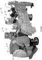
- FIG. 1 is a schematic illustration of a surgical robot 100 for environment property estimation and graphical display according to an embodiment of the current invention.
- the surgical robot 100 includes a master console 102 and a patient-side manipulator 104.
- the master console 102 includes a visual display 106 and manipulator 108.
- the patient-side manipulator 104 includes a manipulation system 110.
- the manipulation system 110 includes a manipulation tool 112 and an imaging system 114.
- a surgical robot 100 includes an imaging system 114 including at least one camera, a processor 116 in communication with the imaging system 114, a manipulation system 110 in communication with the processor 116, and a visual display 106 in communication with the processor 116.
- the processor 116 calculates a mechanical property estimate for an area of an environment based on an environment model of tool-environment interaction data, creates a composite image comprising a mechanical property map of the mechanical property estimate overlaid on an environment image from the at least one camera, and outputs the composite image on the visual display 106.
- the mechanical property is a stiffness.
- the stiffness can be linear or nonlinear.
- the mechanical property is linear or nonlinear damping.
- the mechanical property is damping.
- the mechanical property is any mechanical property that can be detected by the system, such as, e.g., but not limited to, stiffness, damping, or mass, etc.
- a user can utilize the surgical robot 100 to provide a composite image so the user can identify areas of the tissue abnormalities based on estimated stiffness of the tissue.
- the estimated stiffness is calculated using tool-environment interaction data from palpation of the tissue.
- the user manipulates the manipulators 108 of the master console 102 to manually control the surgical robot 100 to palpate the tissue area.
- the user selects the area of tissue to palpate, but the surgical robot 100 controls the palpation of the tissue area.
- the surgical robot 100 automatically palpates the tissue including the tissue abnormality area.
- the processor 116 of the surgical robot 100 instructs the manipulation system 110 to palpate an area of tissue with the manipulation tool 112.
- the processor 116 receives tool-environment interaction data for the interaction between the manipulation tool 112 and the tissue during the palpation.
- the tool-environment interaction data include data for the position of the manipulation tool 112 when palpating the tissue area.
- the tool-environment interaction data can also include other data, such as, for example, velocity and acceleration of the manipulation tool 112, the force exerted by the manipulation tool 112 on the tissue, or the amount of displacement the manipulation tool 112 causes to the tissue. While the manipulation tool 112 is in contact with the tissue, many characteristics of the manipulation tool 112 also correspond to characteristics of the tissue. For example, while the manipulation tool 112 is in contact with the tissue, the change in position of the manipulation tool 112 corresponds to the change in position of the tissue.
- the processor 116 can receive the tool-environment interaction data from a variety of sources.
- the position of the manipulation tool 112 can be known by the processor 116 thorough position sensors in the manipulation system 110, or through analysis of the data from the imaging system 114.
- the processor 116 monitors the position of the manipulation tool 112 and calculates the velocity and acceleration of the manipulation tool based on changes in the position of the manipulation tool 112.
- the manipulation tool 112 includes velocity and acceleration sensors in communication with the processor 116. Determination of other tool-environment interaction data is further described below in regards to Figures 2A, 2B, and 2C .
- the processor 116 receives multiple sets of tool-environment interaction data. Based on the tool-environment interaction data, the processor 116 then calculates a stiffness estimate, representing an estimated stiffness, for the area of tissue palpated.
- the processor 116 uses a tissue model and applies the tool-environment interaction data to the tissue model to estimate the unknown parameters of the tissue model.
- tissue models can be used, such as, e.g., but not limited to, a Kelvin-Voigt model, a Mass-damper-spring model, a Hunt-Crossley model, a 2nd order polynomial model, a 3rd order polynomial model, a 4th order polynomial model, or a 2nd order polynomial and velocity-dependent model.
- estimation techniques for estimating the unknown parameters of the tissue model can also be used, such as, e.g., but not limited to, recursive least squares, adaptive identification, the Kalman filter, and signal processing.
- the processor 116 obtains the stiffness estimate from the estimated unknown parameters of the tissue model.
- the processor 116 uses the stiffness estimate and the environment image from the imaging system 114 to create the composite image.
- the composite image includes a stiffness map of the stiffness estimate overlaid on an environment image from the at least one camera.
- the stiffness map is a graphical representation of the calculated stiffness estimate of one or more areas of the tissue, and is further described below in regards to Figure 3 .
- the processor 116 creates the composite image such that the areas of the stiffness map correspond to the areas of the environment the stiffness map overlays in the environment image.
- Creating a composite image includes creating the stiffness map based on translation of the stiffness estimate to the environment image.
- the processor 116 analyzes the environment image to translate an area of the environment to an area of the environment image showing the area of the environment. Based on the translation, the processor 116 then creates the stiffness map and overlays the stiffness map on the environment image.
- the processor 116 overlays the stiffness map in a semi-transparent fashion so the underlying environment image is still visible in the composite image.
- the composite image is then output on the visual display 106.
- the processor 116 creates the composite image in real time.
- the visual display 106 shows users the composite image.
- the visual display 106 is a stereo display.
- the visual display 106 shows a three dimensional stereo view to the user through two separate displays, one display for each eye. Each of the displays shows a different composite image corresponding to the viewpoint of the environment for that eye.
- the visual display 106 is instead a non-stereo display 118.
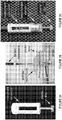
- FIGs 2A, 2B, and 2C are schematic illustrations of a palpation tool attachment according to an embodiment of the current invention.
- Figure 2A depicts an embodiment of an attachment for the manipulation tool 112.
- the attachment includes an instrument extension component and a clear plastic disc.
- the instrument extension component is attached to the manipulation tool 112.
- the clear plastic disc is the contact point for palpating the tissue
- the disc can be made of any other suitable material and can be any other suitable shape.
- the attachment can instead of a separate attachment, the attachment can instead be incorporated into the manipulation tool 112.
- the manipulation tool 112 includes a tool-environment interaction sensor.
- the tool-environment interaction sensor is a force sensor.
- the manipulation tool 112 is arranged so the force sensor measures the force exerted on the environment by the manipulation tool 112. Based on changes in the force measured by the force sensor, the processor 116 can also determine the moment of contact and non-contact between the manipulation tool 112 and the environment.
- the tool-environment interaction data include the force measured by the force sensor and the processor 116 calculates the stiffness estimates based on the measured force and robot position.
- the tool-environment interaction force is not measured by a force sensor but instead estimated from the robot controller, following the method of M. Mahvash, J Gwilliam, R. Agarwal, B. Vagvolgyi, L. Su, D. D. Yuh, and A. M. Okamura, "Force-Feedback Surgical Teleoperator: Controller Design and Palpation Experiments", 16th Symposium on Haptic Interfaces for Virtual Environments and Teleoperator Systems, pp. 465-471, Reno, NV, March 2008 .
- the error between the commanded and actual robot motion is used to estimate the force applied to the robot end-effector.
- Dynamic models of the robot are used to differentiate between forces from the environment (e.g. tissue) and forces from the internal mechanics of the robot (e.g. inertia and friction).
- tool-environment interaction data are visually obtained from the image system 114.
- the processor 116 instructs the manipulation tool 112 to exert a known amount of force on the environment. Based on the image from the image system 114, the processor 116 identifies contact between the manipulation tool 112 and the environment.
- the processor 116 can then determine the amount of displacement in the environment caused by the manipulation tool 112 based on visual analysis of the environment image or based on changes in position data of the manipulation tool 112.
- the tool-environment interaction data include the amount of displacement and the processor 116 calculates the stiffness estimates based on the amount of displacement.
- the tool-environment interaction sensor and visually determined tool-environment interaction data are both used by the surgical robot 100.
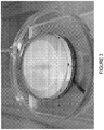
- FIG. 3 is a diagram of a composite image showing a stiffness map overlaid on an image of an environment according to an embodiment of the current invention.
- the processor 116 creates a stiffness map of the tissue from the stiffness estimates.
- the stiffness map is a graphical representation of the estimated stiffness of the tissue.
- the stiffness map is a hue-saturation-luminance (HSL) representation. Hue corresponds to a stiffness value and saturation is calculated by a weighted Gaussian function.
- the processor 116 defines a confidence level for the surrounding areas, which is interpreted as a saturation value. In an embodiment, when multiple confidence levels overlap in the same point, hue is blended to make a blended continuous colored map.
- the processor 116 sums confidence levels to increase reliability at the palpated point.
- the processor 116 updates the stiffness map in real time as new data are gathered.
- the stiffness map is a three-dimensional map (a surface map embedded in three dimensions) and the processor 116 overlays the three-dimensional stiffness map on the environment image.
- the processor 116 receives a stereo view of an environment.
- the stereo view includes two images of the environment from the imaging system 114.
- the processor 116 determines the contours of the environment as shown in the stereo view.
- the processor 116 then creates the composite image so the three dimensional stiffness map corresponds to the contours of the environment.
- the data processing unit may be similar to the processor 116 described with reference to the surgical robot in Figure 1 .
- the data processing unit has at least one input port adapted to receive an environment image from the surgical robot and to receive tool-environment interaction data from the surgical robot, an overlay component in communication with the at least one input port, and an output port in communication with the overlay component.
- the overlay component is adapted to calculate a mechanical property estimate for an area of an environment based on an environment model of tool-environment interaction data, create a composite image comprising a mechanical property map of the mechanical property estimate overlaid on the environment image, and output the composite image to the output port.
- Another embodiment of the current invention is directed to a tangible machine readable storage medium that provides instructions, which when executed by a computing platform cause the computing platform to perform operations including a method including, according to an embodiment of the current invention, determining tool-environment interaction data from a palpation of an area of an environment, calculating a mechanical property estimate of the area of the environment based on the tool-environment interaction data, receiving an environment image, generating a composite image comprising a mechanical property map of the mechanical property estimate overlaid on the environment image, and outputting the composite image on a visual display.
- a real-time graphical overlay technique to display the location of hard objects hidden in soft materials, e.g. a calcified artery inside heart tissue.
- Our approach is to estimate the mechanical properties of tissue using recursive least squares (RLS) and simultaneously overlay a colored stiffness map on the surgeon's visual display.
- the graphical overlay clearly displays the location of a artificial calcified artery, as shown in Figure 3 .
- Another application is online detection of tumors.
- Our proposed technique may also be practical as an alternative to conventional force feedback, since simple force-sensing instruments designed specifically for palpation may be easier to develop than force sensing dexterous manipulation instruments.
- the nonlinear Hunt-Crossley model takes into account the energy loss during impact, which is observed in the Kelvin-Voigt model. While finite element modeling can provide superior tissue modeling, its computational complexity has limited its utility in real-time applications. Misra et al. ( S. Misra, K. T. Ramesh, and A. M. Okamura, "Modeling of tool-tissue interactions for computer-based surgical simulation: A literature review," Presence: Teleoperators and Virtual Environments, vol. 17, no. 5, pp. 463-491, 2008 ) have reviewed the literature on the tool-tissue interaction methods.
- This example describes (1) validation of a mathematical artificial artificial tissue model and (2) use of the model and teleoperated robot to create a real-time graphical overlay to represent tissue stiffness, thus enabling an operator to identify an invisible hard inclusion inside a soft material.
- a hue-saturation-luminance (HSL) representation is used to overlay a semi-transparent colored stiffness map on the environment image.
- Hue corresponds to a stiffness value and saturation is calculated by a weighted Gaussian function.
- a confidence level for the surrounding areas Based on the distance from a palpated point, we define a confidence level for the surrounding areas, which is interpreted as a saturation value.
- hue is blended to make a continuous colored map.
- the confidence levels are summed to increase reliability at the palpated point. This procedure is repeated in real time as new data are added.
- a semi-transparent, colored stiffness map that displays the location of a hard inclusion, without obscuring the surgeon's view of the tissue or surgical instrument.
- the artificial tissue heart model is made from Ecoflex 0030 (part A and B), silicone thinner, and silc pigment (Smooth-on Inc., Easton, PA, USA) mixed in a 24:24:12:1 ratio.
- a coffee stir straw is embedded in the artificial tissue.
- Our surgeon collaborator tested the potential models to make a realistic choice of artificial tissue samples.
- the diameter and thickness of a artificial tissue heart model are approximately 60 mm and 18.5 mm, respectively.
- a coffee stir straw with diameter of 4 mm is embedded at the depth of 5 mm from the surface.
- f ⁇ is an estimated interaction force between the tool and the environment
- x, ⁇ and ⁇ are position, velocity, and acceleration of the tool, respectively.
- the remaining terms, x ⁇ 0 , k ⁇ , b ⁇ , m ⁇ , ⁇ , n ⁇ , ⁇ i , and ⁇ are unknown parameters to be estimated.
- FIG. 2A An instrument extension with a plastic disc, Figure 2A , is attached at the tip of an instrument.
- the diameter of the artificial calcified artery is 4 mm, and the disc is 10 mm in diameter. Due to the size and the flatness of the disc, the tool does not slide off the artery when force is applied.
- the instrument is mounted on a patient-side manipulator of our da Vinci Surgical System, as explained later.
- Figure 2B the artificial heart tissue was placed on a plastic base mounted on a Nano17 transducer (ATI Industrial Automation, Apex, NC, USA).
- ⁇ is a regression vector including known parameters
- ⁇ is an unknown parameter vector
- Model 3 is nonlinear in unknown parameters because of the exponent n ⁇ .
- ⁇ 1 , ⁇ k ⁇ ⁇ Y ⁇ y 1 , ⁇ y 2 , ⁇ , ⁇ y n T ⁇ y i
- Nonlinear least squares has no closed-form solution and requires initial values for the unknown parameters.
- ⁇ 0 [0, 5, 0.3, 1.5] T by trial and error to avoid local minima sometimes observed when ⁇ 0 is a zero vector).
- the iteration number k started from 0 and increased until the norm of the increment parameter vector ⁇ ⁇ was less than 0.001.
- the mean and standard deviation of the force estimation error for each model are summarized in Table I.
- Models 3, 5, 6, and 7 therefore seem to characterize the dynamics of both soft tissue and calcified artery well, while Models 1, 2, and 4 do not.
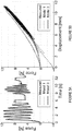
- Figure 4 shows sample plots of interaction data of the tool and the environment.
- Figure 4A and 4B show sample plots of (4A) soft tissue and (4B) calcified artery showing (Top) force vs. elapsed time and (Bottom) force vs. displacement when using a mass-damper-spring model to calculate estimated force.
- Model 3 is a better choice. To discriminate the hard inclusions from the soft surrounding material, we would like to identify a physically meaningful difference. Table II summarizes the estimated parameters of Models 3 and 7. While k ⁇ of Model 3 shows a consistent difference between the artificial tissue and the artificial calcified artery, any parameters of Model 7 do not show a consistent difference.
- Model 3 the Hunt-Crossley model. TABLE II COMPARISON OF ESTIMATED PARAMETERS OF MODELS 3 AND 7 Trial Number Model 3 Model 7 x ⁇ 0 , k ⁇ ⁇ n ⁇ ⁇ 0 ⁇ 1 ⁇ 2 ⁇ Soft Tissue 1 0.708 5.518 0.090 1.679 0.155 3.697 4.588 0.258 2 0.668 5.544 0.115 1570 0.519 0.427 6.687 0286 3 0.416 5.141 0.198 1.391 0.028 5.679 2.461 0.202 4 0.327 4.960 0.134 1.686 0.036 4.867 2.581 0.208 5 1.025 5.984 0.211 1.587 0.373 3.302 5.654 0.306 Calcified Artery 1 0.178 8.687 0.200 1.849 0.352 3.432 6.984 0.294 2 0.249 8.490 0.272 1.934 0.210 4.936 5.701 0.228 3 0.702 10.412 0.411 1.613 0.374 5.374
- Figure 6 shows a schematic illustration of a custom version of the da Vinci Surgical System where the master manipulators and the 3D vision display system are located on the right, and the patient-side manipulators and a stereo camera are on the left.
- Our custom version of the da Vinci Surgical System includes three components: master manipulators, 3D vision system, and patient-side manipulators.
- the hardware is provided by Intuitive Surgical, Inc., and a custom control system has been developed at the Johns Hopkins University to achieve bilateral telemanipulation. More details about the teleoperation system and the control architecture are summarized in ( M. Mahvash, J. Gwilliam, R. Agarwal, B. Vagvolgyi, L.-M. Su, D. D. Yuh, and A. M. Okamura, "Force-feedback surgical teleoperator: Controller design and palpation experiments," in 16th Symposium on Haptic Interfaces for Virtual Environments and Teleoperator Systems, pp. 465-471, 2008 ). Although the user received force feedback based on the position-position controller during an experiment, all we need for estimation are tool-environment interaction data.
- Stramigioli "Contact impedance estimation for robotic systems," IEEE Transactions on Robotics, vol. 21, no. 5, pp. 925-935, 2005 ): ⁇ 1 estimates x ⁇ 0 , k ⁇ , and ⁇ , and ⁇ 2 estimates the exponent n ⁇ . Both estimators are interconnected via feedback. Note that we added the position offset x ⁇ 0 to the original method presented in N. Diolaiti, C. Melchiorri, and S. Stramigioli, "Contact impedance estimation for robotic systems," IEEE Transactions on Robotics, vol. 21, no. 5, pp. 925-935, 2005 .
- the result of this calibration is the transformation frame between the Cartesian manipulator tool tip coordinates and the Cartesian camera frame (the camera frame is centered half way between the two cameras).
- a color map using the HSL representation is overlaid on the stereo camera images to display the stiffness of the palpated points. Since the data are analyzed in real time, while the artificial tissue is being palpated, the estimated stiffness and the palpated position data are simultaneously transferred to a vision computer and displayed by a semitransparent color graphical overlay at a rate of 30 Hz. With transparency of 50%, the camera images are clearly visible behind the overlaid image. Thus, the colored stiffness map does not obscure the user's view of the tool or the surface features of the artificial tissue.
- Hue corresponds to stiffness, and the color ranges from green, passing through yellow, to red.
- the range of stiffness k ⁇ from 6 to 10.
- Saturation value is calculated based on a Gaussian function.
- h ( x ) exp(( x - ⁇ ) 2 / ⁇ ), ranging from 0 to 1.
- x and ⁇ are elements of a vector such that the term (x - ⁇ ) 2 is squared distance between the center of the palpated point and the surrounding regions. The standard deviation ⁇ was chosen such that the size of an overlaid circle corresponds to that of the palpation disc.
- Figure 7A and 7B show plots of (7A) confidence level when summing overlapping probability density functions and (7B) hue indicating changes in stiffness and saturation indicating confidence level.
- FIG. 7A A simple summation interpolation technique is used when two or more probability density functions overlap, as shown in Figure 7A . If the sum is more than 1, it is cut off to 1. Luminance is 0.5 for all pixels to show the overlay in color. Figure 7B shows the HSL bar we used in our system.
- Figure 8A-8D are diagrams of composite images as the stiffness map of the underlying environment shown in the image is developed.
- Figure 8 shows four pictures taken during a trial. As soon as contact between the tool and artificial tissue was detected, a semi-transparent colored circle was displayed on the stereo monitor of the surgeon's console. Each palpation at a single location lasted approximately half a second.
- Figure 8A shows the result of the first palpation.
- Figure 8B there are several circles displayed due to random palpation. When a current palpated area is close to others palpated before, the interpolation technique is used to blend the color and sum the confidence level.
- Figure 8C One of the intermediate results is shown in Figure 8C . At this point, one can see a red area that vertically goes through the center.
- the red region is very distinct, as shown in Figure 8D .
- the width of the red region is approximately 8 mm while the actual width of the artificial calcified artery is 4 mm.
- the size of the overlaid circle or the standard deviation of the Gaussian could be reduced to detect more precise size and location of the artificial calcified artery.
- This example presents the use of a teleoperated surgical robot for online estimation of tissue properties, and identification of a hard object hidden in soft materials using a colored stiffness map overlaid on the surgeon's monitor.
- a teleoperated surgical robot for online estimation of tissue properties, and identification of a hard object hidden in soft materials using a colored stiffness map overlaid on the surgeon's monitor.
- the Hunt-Crossley model which provides the lowest force estimation errors in both self-validation and cross-validation and shows a consistent difference between the artificial tissue and the artificial calcified artery.
- Recursive least squares is used to estimate the unknown parameters of the Hunt-Crossley model.
- the estimated stiffness is transmitted to a vision computer to create a graphical overlay using the hue-saturation-luminance map. The hue of the graphical overlay is determined by the stiffness.
- a confidence level is defined by a weighted Gaussian function, based on distance from a palpated point.
- a simple interpolation technique is used. By probing over the surface of an artificial heart tissue, we successfully acquire a color map showing the location of an artificial calcified artery.
Landscapes
- Health & Medical Sciences (AREA)
- Engineering & Computer Science (AREA)
- Surgery (AREA)
- Life Sciences & Earth Sciences (AREA)
- Nuclear Medicine, Radiotherapy & Molecular Imaging (AREA)
- General Health & Medical Sciences (AREA)
- Veterinary Medicine (AREA)
- Public Health (AREA)
- Animal Behavior & Ethology (AREA)
- Biomedical Technology (AREA)
- Heart & Thoracic Surgery (AREA)
- Medical Informatics (AREA)
- Molecular Biology (AREA)
- Robotics (AREA)
- Oral & Maxillofacial Surgery (AREA)
- Pathology (AREA)
- Radiology & Medical Imaging (AREA)
- Physics & Mathematics (AREA)
- General Physics & Mathematics (AREA)
- Mechanical Engineering (AREA)
- Gynecology & Obstetrics (AREA)
- Automation & Control Theory (AREA)
- Theoretical Computer Science (AREA)
- Human Computer Interaction (AREA)
- General Engineering & Computer Science (AREA)
- Instructional Devices (AREA)
- Manipulator (AREA)
- Measuring And Recording Apparatus For Diagnosis (AREA)
Claims (15)
- Chirurgischer Roboter (100), umfassend:ein bildgebendes System (114) mit mindestens einer Stereokamera;einen Prozessor (116) in Kommunikation mit dem bildgebenden System (114);ein Manipulationssystem (110) in Kommunikation mit dem Prozessor (116), wobei das Manipulationssystem (110) ein Manipulationswerkzeug (112) einschließt; undeine visuelle Anzeige (106) in Kommunikation mit dem Prozessor (116);wobei der Prozessor (116) betreibbar ist, um:das Manipulationssystems (110) anzuweisen, mit dem Manipulationswerkzeug (112) einen Umgebungsbereich abzutasten;Werkzeug-Umgebungs-Interaktionsdaten für eine Interaktion zwischen dem Manipulationswerkzeug (112) und der Umgebung während des Abtastens zu empfangen;ein Umgebungsmodell zu verwenden und die Werkzeug-Umgebungs-Interaktionsdaten auf das Umgebungsmodell anzuwenden, um unbekannte Parameter des Umgebungsmodells zu schätzen;eine Schätzung der mechanischen Eigenschaft des Umgebungsbereichs basierend auf den geschätzten unbekannten Parametern des Umgebungsmodells zu berechnen;Konturen der Umgebung basierend auf einem Umgebungsbild von der mindestens einen Stereokamera zu bestimmen;ein zusammengesetztes Bild zu erzeugen, das ein Kennfeld der mechanischen Eigenschaft der Schätzung der mechanischen Eigenschaft für den Umgebungsbereich umfasst, das so auf das Umgebungsbild von der mindestens einen Stereokamera überlagert ist, dass das Kennfeld der mechanischen Eigenschaft den Konturen der Umgebung entspricht; unddas zusammengesetzte Bild auf der visuellen Anzeige (106) auszugeben.
- Chirurgischer Roboter nach Anspruch 1, wobei der Prozessor (116) betreibbar ist, um das Kennfeld der mechanischen Eigenschaft basierend auf einer Translation der Schätzung der mechanischen Eigenschaft auf das Umgebungsbild zu erzeugen.
- Chirurgischer Roboter nach Anspruch 1, wobei ein Bereich des Kennfelds der mechanischen Eigenschaft, der dem Umgebungsbild überlagert ist, dem Umgebungsbereich entspricht, der dargestellt ist überlagert durch den Bereich des Kennfelds der mechanischen Eigenschaft im Umgebungsbild.
- Chirurgischer Roboter nach Anspruch 3, wobei das Kennfeld der mechanischen Eigenschaft ein farbiges Kennfeld der mechanischen Eigenschaft mit Farbwert-Farbsättigung-Leuchtdichte umfasst, wobei der Farbwert einem Wert einer mechanischen Eigenschaft für einen Bereich des Kennfelds der mechanischen Eigenschaft entspricht und die Farbsättigung einem Konfidenzniveau für den Bereich des Kennfelds der mechanischen Eigenschaft entspricht.
- Chirurgischer Roboter nach Anspruch 1, wobei das Kennfeld der mechanischen Eigenschaft ein gemischtes Kennfeld der mechanischen Eigenschaft umfasst.
- Chirurgischer Roboter nach Anspruch 1, wobei das Manipulationssystem (110) ferner einen Werkzeug-Umgebungs-Interaktionssensor umfasst.
- Chirurgischer Roboter nach Anspruch 6, wobei der Werkzeug-Umgebungs-Interaktionssensor einen Kraftsensor umfasst, wobei die Werkzeug-Umgebungs-Interaktionsdaten einen Kraftbetrag umfassen, der von dem Manipulationssystem (110) auf die Umgebung ausgeübt wird.
- Chirurgischer Roboter nach Anspruch 1, wobei die Werkzeug-Umgebungs-Interaktionsdaten einen Verschiebungsbetrag in der Umgebung umfassen, der durch das Manipulationssystem (110) verursacht wird.
- Chirurgischer Roboter nach Anspruch 1, wobei der Prozessor (116) ferner betreibbar ist, um das zusammengesetzte Bild in Echtzeit zu erzeugen.
- Chirurgischer Roboter nach Anspruch 1, wobei das Umgebungsmodell eine lineare oder nichtlineare Gleichung umfasst, die die mechanische Eigenschaft der Umgebung verwendet, um Kraft- und Bewegungsvariablen in Beziehung zu setzen.
- Chirurgischer Roboter nach Anspruch 1, wobei der Prozessor (116) ferner betreibbar ist, um einen Algorithmus anzuwenden, um die mechanische Eigenschaft basierend auf dem Umgebungsmodell und den Werkzeug-Umgebungs-Interaktionsdaten zu schätzen.
- Chirurgischer Roboter nach Anspruch 1, wobei das Kennfeld der mechanischen Eigenschaft ein Kennfeld der mechanischen Oberflächeneigenschaft umfasst, das in einen dreidimensionalen Raum eingebettet ist.
- Chirurgischer Roboter nach Anspruch 1, wobei die Umgebung mindestens ein Gewebe oder ein Organ umfasst.
- Chirurgischer Roboter nach Anspruch 1, wobei die mechanische Eigenschaft Steifheit umfasst.
- Materielles maschinenlesbares Speichermedium, das Anweisungen bereitstellt, die, wenn sie von einer, einen Prozessor (116) umfassenden Computerplattform ausgeführt werden, die Computerplattform veranlassen, Operationen auszuführen, die ein Verfahren umfassen, das Folgendes umfasst:Anweisen eines Manipulationssystems (110) in Kommunikation mit dem Prozessor (116), einen Umgebungsbereich mit einem Manipulationswerkzeug (112) des Manipulationssystems (110) abzutasten;Empfangen von Werkzeug-Umgebungs-Interaktionsdaten für eine Interaktion zwischen dem Manipulationswerkzeug (112) und der Umgebung während des Abtastens;Verwenden eines Umgebungsmodells und Anwenden der Werkzeug-Umgebungs-Interaktionsdaten auf das Umgebungsmodell, um unbekannte Parameter des Umgebungsmodells zu schätzen;Berechnen einer Schätzung einer mechanischen Eigenschaft des Umgebungsbereichs basierend auf den geschätzten unbekannten Parametern des Umgebungsmodells;Empfangen eines Stereobildes der Umgebung;Bestimmen von Konturen der Umgebung basierend auf dem Stereobild der Umgebung;Erzeugen eines zusammengesetzten Bildes mit einem Kennfeld der mechanischen Eigenschaft der Schätzung der mechanischen Eigenschaft für den Umgebungsbereich, das dem Stereobild der Umgebung überlagert ist, so dass das Kennfeld der mechanischen Eigenschaft den Konturen der Umgebung entspricht; undAusgeben des zusammengesetzten Bildes auf einer visuellen Anzeige (106) in Kommunikation mit dem Prozessor (116).
Applications Claiming Priority (2)
| Application Number | Priority Date | Filing Date | Title |
|---|---|---|---|
| US10668308P | 2008-10-20 | 2008-10-20 | |
| PCT/US2009/061297 WO2010048160A2 (en) | 2008-10-20 | 2009-10-20 | Environment property estimation and graphical display |
Publications (3)
| Publication Number | Publication Date |
|---|---|
| EP2355711A2 EP2355711A2 (de) | 2011-08-17 |
| EP2355711A4 EP2355711A4 (de) | 2012-04-25 |
| EP2355711B1 true EP2355711B1 (de) | 2019-09-11 |
Family
ID=42119935
Family Applications (1)
| Application Number | Title | Priority Date | Filing Date |
|---|---|---|---|
| EP09822545.1A Active EP2355711B1 (de) | 2008-10-20 | 2009-10-20 | Umgebungseigenschaftseinschätzung und grafische anzeige |
Country Status (6)
| Country | Link |
|---|---|
| US (2) | US8700123B2 (de) |
| EP (1) | EP2355711B1 (de) |
| JP (1) | JP5762962B2 (de) |
| KR (1) | KR101713676B1 (de) |
| CN (1) | CN102238916B (de) |
| WO (1) | WO2010048160A2 (de) |
Families Citing this family (169)
| Publication number | Priority date | Publication date | Assignee | Title |
|---|---|---|---|---|
| US11259870B2 (en) | 2005-06-06 | 2022-03-01 | Intuitive Surgical Operations, Inc. | Interactive user interfaces for minimally invasive telesurgical systems |
| ATE540634T1 (de) | 2005-06-06 | 2012-01-15 | Intuitive Surgical Operations | Laparoskopisches ultraschall-robotersystem für chirurgische zwecke |
| EP3395508A1 (de) * | 2005-06-30 | 2018-10-31 | Intuitive Surgical Operations Inc. | Indikator zur kommunikation des werkzeugstatus in der mehrarmigen robotischen telechirurgie |
| US8219178B2 (en) | 2007-02-16 | 2012-07-10 | Catholic Healthcare West | Method and system for performing invasive medical procedures using a surgical robot |
| US10357184B2 (en) | 2012-06-21 | 2019-07-23 | Globus Medical, Inc. | Surgical tool systems and method |
| US10893912B2 (en) | 2006-02-16 | 2021-01-19 | Globus Medical Inc. | Surgical tool systems and methods |
| US10653497B2 (en) | 2006-02-16 | 2020-05-19 | Globus Medical, Inc. | Surgical tool systems and methods |
| US10532466B2 (en) * | 2008-08-22 | 2020-01-14 | Titan Medical Inc. | Robotic hand controller |
| US8332072B1 (en) | 2008-08-22 | 2012-12-11 | Titan Medical Inc. | Robotic hand controller |
| KR101662323B1 (ko) * | 2010-05-28 | 2016-10-04 | 가천의과학대학교 산학협력단 | 의료 영상 장치용 3축 움직임 추적 장치 및 이를 이용한 의료 영상 보정 방법 |
| US8672837B2 (en) | 2010-06-24 | 2014-03-18 | Hansen Medical, Inc. | Methods and devices for controlling a shapeable medical device |
| WO2012131660A1 (en) | 2011-04-01 | 2012-10-04 | Ecole Polytechnique Federale De Lausanne (Epfl) | Robotic system for spinal and other surgeries |
| US9259289B2 (en) | 2011-05-13 | 2016-02-16 | Intuitive Surgical Operations, Inc. | Estimation of a position and orientation of a frame used in controlling movement of a tool |
| KR101800189B1 (ko) | 2012-04-30 | 2017-11-23 | 삼성전자주식회사 | 수술 로봇의 힘 제어 장치 및 방법 |
| US12220120B2 (en) | 2012-06-21 | 2025-02-11 | Globus Medical, Inc. | Surgical robotic system with retractor |
| US12446981B2 (en) | 2012-06-21 | 2025-10-21 | Globus Medical, Inc. | System and method for surgical tool insertion using multiaxis force and moment feedback |
| US20150032164A1 (en) | 2012-06-21 | 2015-01-29 | Globus Medical, Inc. | Methods for Performing Invasive Medical Procedures Using a Surgical Robot |
| US11607149B2 (en) | 2012-06-21 | 2023-03-21 | Globus Medical Inc. | Surgical tool systems and method |
| US11857266B2 (en) | 2012-06-21 | 2024-01-02 | Globus Medical, Inc. | System for a surveillance marker in robotic-assisted surgery |
| US12594001B2 (en) | 2012-06-21 | 2026-04-07 | Globus Medical, Inc. | Apparatus for recording probe movement |
| US10758315B2 (en) | 2012-06-21 | 2020-09-01 | Globus Medical Inc. | Method and system for improving 2D-3D registration convergence |
| US10624710B2 (en) | 2012-06-21 | 2020-04-21 | Globus Medical, Inc. | System and method for measuring depth of instrumentation |
| US11298196B2 (en) | 2012-06-21 | 2022-04-12 | Globus Medical Inc. | Surgical robotic automation with tracking markers and controlled tool advancement |
| US11253327B2 (en) | 2012-06-21 | 2022-02-22 | Globus Medical, Inc. | Systems and methods for automatically changing an end-effector on a surgical robot |
| US12004905B2 (en) | 2012-06-21 | 2024-06-11 | Globus Medical, Inc. | Medical imaging systems using robotic actuators and related methods |
| US11857149B2 (en) | 2012-06-21 | 2024-01-02 | Globus Medical, Inc. | Surgical robotic systems with target trajectory deviation monitoring and related methods |
| US10231791B2 (en) | 2012-06-21 | 2019-03-19 | Globus Medical, Inc. | Infrared signal based position recognition system for use with a robot-assisted surgery |
| US11864745B2 (en) | 2012-06-21 | 2024-01-09 | Globus Medical, Inc. | Surgical robotic system with retractor |
| US11399900B2 (en) | 2012-06-21 | 2022-08-02 | Globus Medical, Inc. | Robotic systems providing co-registration using natural fiducials and related methods |
| US12472008B2 (en) | 2012-06-21 | 2025-11-18 | Globus Medical, Inc. | Robotic fluoroscopic navigation |
| US11395706B2 (en) | 2012-06-21 | 2022-07-26 | Globus Medical Inc. | Surgical robot platform |
| US11793570B2 (en) | 2012-06-21 | 2023-10-24 | Globus Medical Inc. | Surgical robotic automation with tracking markers |
| US11864839B2 (en) | 2012-06-21 | 2024-01-09 | Globus Medical Inc. | Methods of adjusting a virtual implant and related surgical navigation systems |
| US11974822B2 (en) | 2012-06-21 | 2024-05-07 | Globus Medical Inc. | Method for a surveillance marker in robotic-assisted surgery |
| US12329593B2 (en) | 2012-06-21 | 2025-06-17 | Globus Medical, Inc. | Surgical robotic automation with tracking markers |
| US11116576B2 (en) | 2012-06-21 | 2021-09-14 | Globus Medical Inc. | Dynamic reference arrays and methods of use |
| US11045267B2 (en) | 2012-06-21 | 2021-06-29 | Globus Medical, Inc. | Surgical robotic automation with tracking markers |
| US12310683B2 (en) | 2012-06-21 | 2025-05-27 | Globus Medical, Inc. | Surgical tool systems and method |
| US11317971B2 (en) | 2012-06-21 | 2022-05-03 | Globus Medical, Inc. | Systems and methods related to robotic guidance in surgery |
| US10136954B2 (en) | 2012-06-21 | 2018-11-27 | Globus Medical, Inc. | Surgical tool systems and method |
| US10350013B2 (en) | 2012-06-21 | 2019-07-16 | Globus Medical, Inc. | Surgical tool systems and methods |
| US12262954B2 (en) | 2012-06-21 | 2025-04-01 | Globus Medical, Inc. | Surgical robotic automation with tracking markers |
| EP2863827B1 (de) | 2012-06-21 | 2022-11-16 | Globus Medical, Inc. | Chirurgische roboterplattform |
| US12465433B2 (en) | 2012-06-21 | 2025-11-11 | Globus Medical Inc. | Methods of adjusting a virtual implant and related surgical navigation systems |
| US9057600B2 (en) | 2013-03-13 | 2015-06-16 | Hansen Medical, Inc. | Reducing incremental measurement sensor error |
| US9014851B2 (en) | 2013-03-15 | 2015-04-21 | Hansen Medical, Inc. | Systems and methods for tracking robotically controlled medical instruments |
| US20140323904A1 (en) * | 2013-04-30 | 2014-10-30 | Elwha Llc | Stabilized device for remote palpation of tissue |
| US11020016B2 (en) | 2013-05-30 | 2021-06-01 | Auris Health, Inc. | System and method for displaying anatomy and devices on a movable display |
| KR101483428B1 (ko) * | 2013-09-30 | 2015-01-19 | 건국대학교 산학협력단 | 레이저 빔을 이용하여 촉감을 제공할 수 있는 수술용 로봇 장치 |
| US9283048B2 (en) | 2013-10-04 | 2016-03-15 | KB Medical SA | Apparatus and systems for precise guidance of surgical tools |
| US9241771B2 (en) | 2014-01-15 | 2016-01-26 | KB Medical SA | Notched apparatus for guidance of an insertable instrument along an axis during spinal surgery |
| EP3104803B1 (de) | 2014-02-11 | 2021-09-15 | KB Medical SA | Steriler griff zur kontrolle eines robotischen chirurgiesystems aus einem sterilen feld |
| CN106659537B (zh) | 2014-04-24 | 2019-06-11 | Kb医疗公司 | 结合机器人手术系统使用的手术器械固持器 |
| CN107072673A (zh) | 2014-07-14 | 2017-08-18 | Kb医疗公司 | 用于在骨组织中制备孔的防滑手术器械 |
| EP3226781B1 (de) | 2014-12-02 | 2018-08-01 | KB Medical SA | Roboterunterstützte volumenentfernung in der chirurgie |
| US10013808B2 (en) | 2015-02-03 | 2018-07-03 | Globus Medical, Inc. | Surgeon head-mounted display apparatuses |
| EP3258872B1 (de) | 2015-02-18 | 2023-04-26 | KB Medical SA | Syteme zur durchführung minimalinvasiver spinal-chirurgie mittles eines robotischen-chirurgischen system unter benutzung einer perkutanen technik |
| US9622831B2 (en) * | 2015-05-20 | 2017-04-18 | Siemens Healthcare Gmbh | Method and apparatus to provide updated patient images during robotic surgery |
| US10376335B2 (en) * | 2015-05-20 | 2019-08-13 | Siemens Healthcare Gmbh | Method and apparatus to provide updated patient images during robotic surgery |
| US10058394B2 (en) | 2015-07-31 | 2018-08-28 | Globus Medical, Inc. | Robot arm and methods of use |
| US10646298B2 (en) | 2015-07-31 | 2020-05-12 | Globus Medical, Inc. | Robot arm and methods of use |
| US10080615B2 (en) | 2015-08-12 | 2018-09-25 | Globus Medical, Inc. | Devices and methods for temporary mounting of parts to bone |
| EP3344179B1 (de) | 2015-08-31 | 2021-06-30 | KB Medical SA | Robotische chirurgische systeme |
| US10034716B2 (en) | 2015-09-14 | 2018-07-31 | Globus Medical, Inc. | Surgical robotic systems and methods thereof |
| US9771092B2 (en) | 2015-10-13 | 2017-09-26 | Globus Medical, Inc. | Stabilizer wheel assembly and methods of use |
| CN105662478B (zh) * | 2015-12-23 | 2019-01-25 | 电子科技大学 | 一种用于机器人辅助微创手术的触诊器械及使用方法 |
| US10117632B2 (en) | 2016-02-03 | 2018-11-06 | Globus Medical, Inc. | Portable medical imaging system with beam scanning collimator |
| US10842453B2 (en) | 2016-02-03 | 2020-11-24 | Globus Medical, Inc. | Portable medical imaging system |
| US11058378B2 (en) | 2016-02-03 | 2021-07-13 | Globus Medical, Inc. | Portable medical imaging system |
| US10448910B2 (en) | 2016-02-03 | 2019-10-22 | Globus Medical, Inc. | Portable medical imaging system |
| US11883217B2 (en) | 2016-02-03 | 2024-01-30 | Globus Medical, Inc. | Portable medical imaging system and method |
| US10866119B2 (en) | 2016-03-14 | 2020-12-15 | Globus Medical, Inc. | Metal detector for detecting insertion of a surgical device into a hollow tube |
| EP3241518B1 (de) | 2016-04-11 | 2024-10-23 | Globus Medical, Inc | Systeme für chirurgische werkzeuge |
| US10390895B2 (en) | 2016-08-16 | 2019-08-27 | Ethicon Llc | Control of advancement rate and application force based on measured forces |
| US10531929B2 (en) * | 2016-08-16 | 2020-01-14 | Ethicon Llc | Control of robotic arm motion based on sensed load on cutting tool |
| US10918445B2 (en) | 2016-12-19 | 2021-02-16 | Ethicon Llc | Surgical system with augmented reality display |
| EP3360502A3 (de) | 2017-01-18 | 2018-10-31 | KB Medical SA | Robotische navigation von robotischen chirurgischen systemen |
| US11071594B2 (en) | 2017-03-16 | 2021-07-27 | KB Medical SA | Robotic navigation of robotic surgical systems |
| US20180289432A1 (en) | 2017-04-05 | 2018-10-11 | Kb Medical, Sa | Robotic surgical systems for preparing holes in bone tissue and methods of their use |
| DE102017005581B4 (de) * | 2017-06-13 | 2019-02-21 | Kuka Deutschland Gmbh | Steuern eines Roboters |
| US10022192B1 (en) | 2017-06-23 | 2018-07-17 | Auris Health, Inc. | Automatically-initialized robotic systems for navigation of luminal networks |
| US10675094B2 (en) | 2017-07-21 | 2020-06-09 | Globus Medical Inc. | Robot surgical platform |
| US11357548B2 (en) | 2017-11-09 | 2022-06-14 | Globus Medical, Inc. | Robotic rod benders and related mechanical and motor housings |
| US12544109B2 (en) | 2017-11-09 | 2026-02-10 | Globus Medical, Inc. | Robotic rod benders and related mechanical and motor housings |
| US10898252B2 (en) | 2017-11-09 | 2021-01-26 | Globus Medical, Inc. | Surgical robotic systems for bending surgical rods, and related methods and devices |
| US11794338B2 (en) | 2017-11-09 | 2023-10-24 | Globus Medical Inc. | Robotic rod benders and related mechanical and motor housings |
| US11134862B2 (en) | 2017-11-10 | 2021-10-05 | Globus Medical, Inc. | Methods of selecting surgical implants and related devices |
| WO2019120481A1 (en) * | 2017-12-19 | 2019-06-27 | Abb Schweiz Ag | System and method for determining a transformation representation |
| US20190254753A1 (en) | 2018-02-19 | 2019-08-22 | Globus Medical, Inc. | Augmented reality navigation systems for use with robotic surgical systems and methods of their use |
| JP7225259B2 (ja) | 2018-03-28 | 2023-02-20 | オーリス ヘルス インコーポレイテッド | 器具の推定位置を示すためのシステム及び方法 |
| US10573023B2 (en) | 2018-04-09 | 2020-02-25 | Globus Medical, Inc. | Predictive visualization of medical imaging scanner component movement |
| CN110831538B (zh) | 2018-05-31 | 2023-01-24 | 奥瑞斯健康公司 | 基于图像的气道分析和映射 |
| US11337742B2 (en) | 2018-11-05 | 2022-05-24 | Globus Medical Inc | Compliant orthopedic driver |
| US11278360B2 (en) | 2018-11-16 | 2022-03-22 | Globus Medical, Inc. | End-effectors for surgical robotic systems having sealed optical components |
| US11744655B2 (en) | 2018-12-04 | 2023-09-05 | Globus Medical, Inc. | Drill guide fixtures, cranial insertion fixtures, and related methods and robotic systems |
| US11602402B2 (en) | 2018-12-04 | 2023-03-14 | Globus Medical, Inc. | Drill guide fixtures, cranial insertion fixtures, and related methods and robotic systems |
| US11918313B2 (en) | 2019-03-15 | 2024-03-05 | Globus Medical Inc. | Active end effectors for surgical robots |
| US12478444B2 (en) | 2019-03-21 | 2025-11-25 | The Board Of Trustees Of The Leland Stanford Junior University | Systems and methods for localization based on machine learning |
| US11419616B2 (en) | 2019-03-22 | 2022-08-23 | Globus Medical, Inc. | System for neuronavigation registration and robotic trajectory guidance, robotic surgery, and related methods and devices |
| US11806084B2 (en) | 2019-03-22 | 2023-11-07 | Globus Medical, Inc. | System for neuronavigation registration and robotic trajectory guidance, and related methods and devices |
| US11317978B2 (en) | 2019-03-22 | 2022-05-03 | Globus Medical, Inc. | System for neuronavigation registration and robotic trajectory guidance, robotic surgery, and related methods and devices |
| US11382549B2 (en) | 2019-03-22 | 2022-07-12 | Globus Medical, Inc. | System for neuronavigation registration and robotic trajectory guidance, and related methods and devices |
| US20200297357A1 (en) | 2019-03-22 | 2020-09-24 | Globus Medical, Inc. | System for neuronavigation registration and robotic trajectory guidance, robotic surgery, and related methods and devices |
| US11571265B2 (en) | 2019-03-22 | 2023-02-07 | Globus Medical Inc. | System for neuronavigation registration and robotic trajectory guidance, robotic surgery, and related methods and devices |
| CN110007601B (zh) * | 2019-05-06 | 2022-03-25 | 广东工业大学 | 一种双边遥操作系统的控制装置和设备 |
| US11045179B2 (en) | 2019-05-20 | 2021-06-29 | Global Medical Inc | Robot-mounted retractor system |
| US11628023B2 (en) | 2019-07-10 | 2023-04-18 | Globus Medical, Inc. | Robotic navigational system for interbody implants |
| EP4021329B1 (de) | 2019-08-30 | 2025-12-10 | Auris Health, Inc. | System und verfahren für instrumentenbildzuverlässigkeit |
| US11207141B2 (en) | 2019-08-30 | 2021-12-28 | Auris Health, Inc. | Systems and methods for weight-based registration of location sensors |
| US12396692B2 (en) | 2019-09-24 | 2025-08-26 | Globus Medical, Inc. | Compound curve cable chain |
| US11571171B2 (en) | 2019-09-24 | 2023-02-07 | Globus Medical, Inc. | Compound curve cable chain |
| US12329391B2 (en) | 2019-09-27 | 2025-06-17 | Globus Medical, Inc. | Systems and methods for robot-assisted knee arthroplasty surgery |
| US11864857B2 (en) | 2019-09-27 | 2024-01-09 | Globus Medical, Inc. | Surgical robot with passive end effector |
| US11426178B2 (en) | 2019-09-27 | 2022-08-30 | Globus Medical Inc. | Systems and methods for navigating a pin guide driver |
| US11890066B2 (en) | 2019-09-30 | 2024-02-06 | Globus Medical, Inc | Surgical robot with passive end effector |
| US12408929B2 (en) | 2019-09-27 | 2025-09-09 | Globus Medical, Inc. | Systems and methods for navigating a pin guide driver |
| US11510684B2 (en) | 2019-10-14 | 2022-11-29 | Globus Medical, Inc. | Rotary motion passive end effector for surgical robots in orthopedic surgeries |
| US11992373B2 (en) | 2019-12-10 | 2024-05-28 | Globus Medical, Inc | Augmented reality headset with varied opacity for navigated robotic surgery |
| US12220176B2 (en) | 2019-12-10 | 2025-02-11 | Globus Medical, Inc. | Extended reality instrument interaction zone for navigated robotic |
| US12133772B2 (en) | 2019-12-10 | 2024-11-05 | Globus Medical, Inc. | Augmented reality headset for navigated robotic surgery |
| US12064189B2 (en) | 2019-12-13 | 2024-08-20 | Globus Medical, Inc. | Navigated instrument for use in robotic guided surgery |
| US11464581B2 (en) | 2020-01-28 | 2022-10-11 | Globus Medical, Inc. | Pose measurement chaining for extended reality surgical navigation in visible and near infrared spectrums |
| US11382699B2 (en) | 2020-02-10 | 2022-07-12 | Globus Medical Inc. | Extended reality visualization of optical tool tracking volume for computer assisted navigation in surgery |
| US12414752B2 (en) | 2020-02-17 | 2025-09-16 | Globus Medical, Inc. | System and method of determining optimal 3-dimensional position and orientation of imaging device for imaging patient bones |
| US11207150B2 (en) | 2020-02-19 | 2021-12-28 | Globus Medical, Inc. | Displaying a virtual model of a planned instrument attachment to ensure correct selection of physical instrument attachment |
| RU2720830C1 (ru) * | 2020-03-19 | 2020-05-13 | Ассистирующие Хирургические Технологии (Аст), Лтд | Ассистирующий хирургический комплекс |
| US11253216B2 (en) | 2020-04-28 | 2022-02-22 | Globus Medical Inc. | Fixtures for fluoroscopic imaging systems and related navigation systems and methods |
| US11607277B2 (en) | 2020-04-29 | 2023-03-21 | Globus Medical, Inc. | Registration of surgical tool with reference array tracked by cameras of an extended reality headset for assisted navigation during surgery |
| US11153555B1 (en) | 2020-05-08 | 2021-10-19 | Globus Medical Inc. | Extended reality headset camera system for computer assisted navigation in surgery |
| US11382700B2 (en) | 2020-05-08 | 2022-07-12 | Globus Medical Inc. | Extended reality headset tool tracking and control |
| US11510750B2 (en) | 2020-05-08 | 2022-11-29 | Globus Medical, Inc. | Leveraging two-dimensional digital imaging and communication in medicine imagery in three-dimensional extended reality applications |
| CN111745643A (zh) * | 2020-05-28 | 2020-10-09 | 西华大学 | 主机器人和从机器人遥操作系统位置控制方法 |
| US12070276B2 (en) | 2020-06-09 | 2024-08-27 | Globus Medical Inc. | Surgical object tracking in visible light via fiducial seeding and synthetic image registration |
| US11317973B2 (en) | 2020-06-09 | 2022-05-03 | Globus Medical, Inc. | Camera tracking bar for computer assisted navigation during surgery |
| US11382713B2 (en) | 2020-06-16 | 2022-07-12 | Globus Medical, Inc. | Navigated surgical system with eye to XR headset display calibration |
| US11877807B2 (en) | 2020-07-10 | 2024-01-23 | Globus Medical, Inc | Instruments for navigated orthopedic surgeries |
| US11793588B2 (en) | 2020-07-23 | 2023-10-24 | Globus Medical, Inc. | Sterile draping of robotic arms |
| US11737831B2 (en) | 2020-09-02 | 2023-08-29 | Globus Medical Inc. | Surgical object tracking template generation for computer assisted navigation during surgical procedure |
| US11523785B2 (en) | 2020-09-24 | 2022-12-13 | Globus Medical, Inc. | Increased cone beam computed tomography volume length without requiring stitching or longitudinal C-arm movement |
| US11911112B2 (en) | 2020-10-27 | 2024-02-27 | Globus Medical, Inc. | Robotic navigational system |
| US12076091B2 (en) | 2020-10-27 | 2024-09-03 | Globus Medical, Inc. | Robotic navigational system |
| US11941814B2 (en) | 2020-11-04 | 2024-03-26 | Globus Medical Inc. | Auto segmentation using 2-D images taken during 3-D imaging spin |
| US11717350B2 (en) | 2020-11-24 | 2023-08-08 | Globus Medical Inc. | Methods for robotic assistance and navigation in spinal surgery and related systems |
| US12161433B2 (en) | 2021-01-08 | 2024-12-10 | Globus Medical, Inc. | System and method for ligament balancing with robotic assistance |
| US12150728B2 (en) | 2021-04-14 | 2024-11-26 | Globus Medical, Inc. | End effector for a surgical robot |
| US12178523B2 (en) | 2021-04-19 | 2024-12-31 | Globus Medical, Inc. | Computer assisted surgical navigation system for spine procedures |
| DE202021102512U1 (de) | 2021-05-07 | 2022-05-10 | Deutsches Zentrum für Luft- und Raumfahrt e.V. | Robotisches Telemanipulationssystem mit adaptierbarem Autonomiegrad, Verwendung eines robotischen Telemanipulationssystems, autonomes medizinisches Robotersystem |
| US12458454B2 (en) | 2021-06-21 | 2025-11-04 | Globus Medical, Inc. | Gravity compensation of end effector arm for robotic surgical system |
| US11857273B2 (en) | 2021-07-06 | 2024-01-02 | Globus Medical, Inc. | Ultrasonic robotic surgical navigation |
| US12484969B2 (en) | 2021-07-06 | 2025-12-02 | Globdus Medical Inc. | Ultrasonic robotic surgical navigation |
| US11439444B1 (en) | 2021-07-22 | 2022-09-13 | Globus Medical, Inc. | Screw tower and rod reduction tool |
| US12213745B2 (en) | 2021-09-16 | 2025-02-04 | Globus Medical, Inc. | Extended reality systems for visualizing and controlling operating room equipment |
| US12184636B2 (en) | 2021-10-04 | 2024-12-31 | Globus Medical, Inc. | Validating credential keys based on combinations of credential value strings and input order strings |
| US12238087B2 (en) | 2021-10-04 | 2025-02-25 | Globus Medical, Inc. | Validating credential keys based on combinations of credential value strings and input order strings |
| US12602775B2 (en) | 2021-10-20 | 2026-04-14 | Globus Medical Inc. | Interpolation of medical images |
| US20230165639A1 (en) | 2021-12-01 | 2023-06-01 | Globus Medical, Inc. | Extended reality systems with three-dimensional visualizations of medical image scan slices |
| EP4449394A1 (de) * | 2021-12-17 | 2024-10-23 | Intuitive Surgical Operations, Inc. | Systeme und verfahren zur bestimmung von materialeigenschaftswerten für ein dreidimensionales virtuelles modell eines anatomischen objekts |
| US11918304B2 (en) | 2021-12-20 | 2024-03-05 | Globus Medical, Inc | Flat panel registration fixture and method of using same |
| US12544146B2 (en) | 2022-02-11 | 2026-02-10 | Globus Medical, Inc. | Apparatus and method for removing circular trackers attached to a tracking array |
| US12103480B2 (en) | 2022-03-18 | 2024-10-01 | Globus Medical Inc. | Omni-wheel cable pusher |
| US12048493B2 (en) | 2022-03-31 | 2024-07-30 | Globus Medical, Inc. | Camera tracking system identifying phantom markers during computer assisted surgery navigation |
| US12394086B2 (en) | 2022-05-10 | 2025-08-19 | Globus Medical, Inc. | Accuracy check and automatic calibration of tracked instruments |
| US12161427B2 (en) | 2022-06-08 | 2024-12-10 | Globus Medical, Inc. | Surgical navigation system with flat panel registration fixture |
| US12226169B2 (en) | 2022-07-15 | 2025-02-18 | Globus Medical, Inc. | Registration of 3D and 2D images for surgical navigation and robotic guidance without using radiopaque fiducials in the images |
| US20240020840A1 (en) | 2022-07-15 | 2024-01-18 | Globus Medical, Inc. | REGISTRATION OF 3D and 2D IMAGES FOR SURGICAL NAVIGATION AND ROBOTIC GUIDANCE WITHOUT USING RADIOPAQUE FIDUCIALS IN THE IMAGES |
| CN115005998B (zh) * | 2022-08-08 | 2022-10-04 | 科弛医疗科技(北京)有限公司 | 一种手术机器人系统及其机械臂防干涉调整方法 |
| US12318150B2 (en) | 2022-10-11 | 2025-06-03 | Globus Medical Inc. | Camera tracking system for computer assisted surgery navigation |
| US12502220B2 (en) | 2022-11-15 | 2025-12-23 | Globus Medical, Inc. | Machine learning system for spinal surgeries |
| CN116572249B (zh) * | 2023-06-07 | 2024-01-02 | 哈尔滨理工大学 | 一种基于三模态切换机制的柔性机械臂遥操作控制方法 |
Family Cites Families (41)
| Publication number | Priority date | Publication date | Assignee | Title |
|---|---|---|---|---|
| US4144877A (en) | 1976-08-12 | 1979-03-20 | Yeda Research And Development Co. Ltd. | Instrument for viscoelastic measurement |
| US4250894A (en) | 1978-11-14 | 1981-02-17 | Yeda Research & Development Co., Ltd. | Instrument for viscoelastic measurement |
| IL69471A (en) | 1983-08-12 | 1987-07-31 | Benjamin Gavish | Method and device for non-invasively monitoring the instantaneous fluctuations in the viscoelastic properties of a soft tissue |
| US4802487A (en) | 1987-03-26 | 1989-02-07 | Washington Research Foundation | Endoscopically deliverable ultrasound imaging system |
| YU47190B (sh) | 1988-02-19 | 1995-01-31 | Institut Za Opštu I Fizičku Hemiju | Uredjaj za neinvazivno akustičko ispitivanje elastičnosti mekih bioloških materijala |
| US5293870A (en) | 1989-11-17 | 1994-03-15 | Board Of Regents The University Of Texas System | Method and apparatus for elastographic measurement and imaging |
| US5107837A (en) | 1989-11-17 | 1992-04-28 | Board Of Regents, University Of Texas | Method and apparatus for measurement and imaging of tissue compressibility or compliance |
| US5099848A (en) | 1990-11-02 | 1992-03-31 | University Of Rochester | Method and apparatus for breast imaging and tumor detection using modal vibration analysis |
| EP0515091B1 (de) | 1991-05-21 | 1997-01-02 | Jack Fisher | System und Verfahren zur Messung von mechanischen Eigenschaften von elastischen Materialien |
| US5524636A (en) | 1992-12-21 | 1996-06-11 | Artann Corporation Dba Artann Laboratories | Method and apparatus for elasticity imaging |
| US5860934A (en) | 1992-12-21 | 1999-01-19 | Artann Corporation | Method and device for mechanical imaging of breast |
| US5678565A (en) | 1992-12-21 | 1997-10-21 | Artann Corporation | Ultrasonic elasticity imaging method and device |
| JP3539645B2 (ja) * | 1995-02-16 | 2004-07-07 | 株式会社日立製作所 | 遠隔手術支援装置 |
| US5814038A (en) | 1995-06-07 | 1998-09-29 | Sri International | Surgical manipulator for a telerobotic system |
| US5833634A (en) | 1995-11-09 | 1998-11-10 | Uromed Corporation | Tissue examination |
| US5916160A (en) | 1996-04-09 | 1999-06-29 | Arcan; Mircea | Real-time imaging contact gauge and visual feedback interactive apparatus including same |
| US5839441A (en) | 1996-06-03 | 1998-11-24 | The Trustees Of The University Of Pennsylvania | Marking tumors and solid objects in the body with ultrasound |
| US5851180A (en) | 1996-07-12 | 1998-12-22 | United States Surgical Corporation | Traction-inducing compression assembly for enhanced tissue imaging |
| US5989199A (en) | 1996-11-27 | 1999-11-23 | Assurance Medical, Inc. | Tissue examination |
| EP0908137A1 (de) | 1997-10-06 | 1999-04-14 | Technologiestichting STW | Verfahren und Gerät für die Bilddarstellung von Lumen oder andere Körperhöhle und dessen Umrandungsgewebe |
| US6063031A (en) | 1997-10-14 | 2000-05-16 | Assurance Medical, Inc. | Diagnosis and treatment of tissue with instruments |
| US6192143B1 (en) | 1997-10-24 | 2001-02-20 | Ultratouch Corporation | Apparatus for detecting very small breast anomalies |
| US6351549B1 (en) | 1997-10-24 | 2002-02-26 | Ultratouch Corporation | Detection head for an apparatus for detecting very small breast anomalies |
| US6270459B1 (en) | 1998-05-26 | 2001-08-07 | The Board Of Regents Of The University Of Texas System | Method for estimating and imaging of transverse displacements, transverse strains and strain ratios |
| EP1105044A1 (de) | 1998-07-21 | 2001-06-13 | Acoustic Sciences Associates | Synthethische, strukturelle bildgebung und volumenabschätzung von biologischen gewebeorganen |
| US8229549B2 (en) * | 2004-07-09 | 2012-07-24 | Tyco Healthcare Group Lp | Surgical imaging device |
| US6352507B1 (en) | 1999-08-23 | 2002-03-05 | G.E. Vingmed Ultrasound As | Method and apparatus for providing real-time calculation and display of tissue deformation in ultrasound imaging |
| US6676607B2 (en) | 2000-01-03 | 2004-01-13 | The Johns Hopkins University | Intraoperative microsurgical ultrasonic device and methods related thereto |
| US6511427B1 (en) | 2000-03-10 | 2003-01-28 | Acuson Corporation | System and method for assessing body-tissue properties using a medical ultrasound transducer probe with a body-tissue parameter measurement mechanism |
| US6468231B2 (en) | 2000-03-31 | 2002-10-22 | Artann Laboratories | Self-palpation device for examination of breast |
| US6371912B1 (en) | 2000-04-05 | 2002-04-16 | Duke University | Method and apparatus for the identification and characterization of regions of altered stiffness |
| US6514204B2 (en) | 2000-07-20 | 2003-02-04 | Riverside Research Institute | Methods for estimating tissue strain |
| US6508768B1 (en) | 2000-11-22 | 2003-01-21 | University Of Kansas Medical Center | Ultrasonic elasticity imaging |
| US6569108B2 (en) | 2001-03-28 | 2003-05-27 | Profile, Llc | Real time mechanical imaging of the prostate |
| US6758815B2 (en) * | 2001-10-17 | 2004-07-06 | Richard Bruce Bernardi | Apparatus and method for indicating mechanical stiffness properties of body tissue |
| JP2003252242A (ja) * | 2002-02-26 | 2003-09-10 | Denso Corp | 車両のフロントエンド構造 |
| US7166075B2 (en) | 2002-03-08 | 2007-01-23 | Wisconsin Alumni Research Foundation | Elastographic imaging of in vivo soft tissue |
| JP3932482B2 (ja) | 2002-10-18 | 2007-06-20 | 株式会社日立メディコ | 超音波診断装置 |
| US8079950B2 (en) | 2005-09-29 | 2011-12-20 | Intuitive Surgical Operations, Inc. | Autofocus and/or autoscaling in telesurgery |
| US8213041B2 (en) | 2006-09-25 | 2012-07-03 | Kyocera Mita Corporation | Image forming apparatus provided with an image filing function for saving files in an organized manner |
| JP2008134373A (ja) * | 2006-11-28 | 2008-06-12 | Mitsubishi Precision Co Ltd | 手術シミュレータ用生体データ作成方法及びシステム、並びに手術シミュレーション方法及び手術シミュレータ |
-
2009
- 2009-10-20 EP EP09822545.1A patent/EP2355711B1/de active Active
- 2009-10-20 KR KR1020117011478A patent/KR101713676B1/ko active Active
- 2009-10-20 US US13/124,350 patent/US8700123B2/en active Active
- 2009-10-20 WO PCT/US2009/061297 patent/WO2010048160A2/en not_active Ceased
- 2009-10-20 CN CN2009801465037A patent/CN102238916B/zh active Active
- 2009-10-20 JP JP2011532328A patent/JP5762962B2/ja active Active
-
2014
- 2014-04-09 US US14/248,794 patent/US9867668B2/en active Active
Non-Patent Citations (2)
| Title |
|---|
| HOFF W ET AL: "Surfaces from stereo: integrating feature matching, disparity estimation, and contour detection", IEEE TRANSACTIONS ON PATTERN ANALYSIS AND MACHINE INTELLIGENCE, IEEE COMPUTER SOCIETY, USA, vol. 11, no. 2, 1 February 1989 (1989-02-01), pages 121 - 136, XP011478204, ISSN: 0162-8828, DOI: 10.1109/34.16709 * |
| SARTHAK MISRA ET AL: "Modeling of Tool-Tissue Interactions for Computer-Based Surgical Simulation: A Literature Review", PRESENCE, vol. 17, no. 5, 1 October 2008 (2008-10-01), US, pages 463 - 491, XP055481782, ISSN: 1054-7460, DOI: 10.1162/pres.17.5.463 * |
Also Published As
| Publication number | Publication date |
|---|---|
| JP2012506260A (ja) | 2012-03-15 |
| EP2355711A4 (de) | 2012-04-25 |
| US20140222025A1 (en) | 2014-08-07 |
| EP2355711A2 (de) | 2011-08-17 |
| US9867668B2 (en) | 2018-01-16 |
| WO2010048160A3 (en) | 2010-08-05 |
| KR20110075025A (ko) | 2011-07-05 |
| WO2010048160A2 (en) | 2010-04-29 |
| KR101713676B1 (ko) | 2017-03-08 |
| JP5762962B2 (ja) | 2015-08-12 |
| US20110201885A1 (en) | 2011-08-18 |
| US8700123B2 (en) | 2014-04-15 |
| CN102238916A (zh) | 2011-11-09 |
| CN102238916B (zh) | 2013-12-04 |
Similar Documents
| Publication | Publication Date | Title |
|---|---|---|
| EP2355711B1 (de) | Umgebungseigenschaftseinschätzung und grafische anzeige | |
| Yamamoto et al. | Tissue property estimation and graphical display for teleoperated robot-assisted surgery | |
| Chua et al. | Toward force estimation in robot-assisted surgery using deep learning with vision and robot state | |
| Mahvash et al. | Force-feedback surgical teleoperator: Controller design and palpation experiments | |
| US11998289B2 (en) | Method and system for autonomous therapy | |
| Talasaz et al. | Integration of force reflection with tactile sensing for minimally invasive robotics-assisted tumor localization | |
| US8594841B2 (en) | Visual force feedback in a minimally invasive surgical procedure | |
| EP2745795B1 (de) | System zur Durchführung von 3-D-Werkzeugverfolgung durch Fusion von Daten, die von einem Sensor und/oder einer Kamera bei einer minimalinvasiven robotergestützten Operation abgeleitet wurden | |
| Dewan et al. | Vision-based assistance for ophthalmic micro-surgery | |
| US8706301B2 (en) | Obtaining force information in a minimally invasive surgical procedure | |
| EP3473202B1 (de) | Robotersystem für minimal invasive chirurgie | |
| Gwilliam et al. | Effects of haptic and graphical force feedback on teleoperated palpation | |
| EP2942029A1 (de) | Chirurgische roboter und steuerungsverfahren dafür | |
| Kennedy et al. | A novel approach to robotic cardiac surgery using haptics and vision | |
| Jackson et al. | Needle-tissue interaction force state estimation for robotic surgical suturing | |
| Mohareri et al. | Bimanual telerobotic surgery with asymmetric force feedback: A daVinci® surgical system implementation | |
| Ebrahimi et al. | Stochastic force-based insertion depth and tip position estimations of flexible FBG-equipped instruments in robotic retinal surgery | |
| Talasaz et al. | Remote palpation to localize tumors in robot-assisted minimally invasive approach | |
| Li et al. | A novel tumor localization method using haptic palpation based on soft tissue probing data | |
| Yasin et al. | Evaluation of hybrid control and palpation assistance for situational awareness in telemanipulated task execution | |
| Takács et al. | The other end of human–robot interaction: Models for safe and efficient tool–tissue interactions | |
| Talasaz et al. | Haptics-enabled teleoperation for robot-assisted tumor localization | |
| Trejos et al. | Design of a sensorized instrument for skills assessment and training in minimally invasive surgery | |
| Jackson et al. | Characterizing functional upper extremity movement in haptic virtual environments | |
| Yamamoto | Applying tissue models in teleoperated robot-assisted surgery |
Legal Events
| Date | Code | Title | Description |
|---|---|---|---|
| PUAI | Public reference made under article 153(3) epc to a published international application that has entered the european phase |
Free format text: ORIGINAL CODE: 0009012 |
|
| 17P | Request for examination filed |
Effective date: 20110519 |
|
| AK | Designated contracting states |
Kind code of ref document: A2 Designated state(s): AT BE BG CH CY CZ DE DK EE ES FI FR GB GR HR HU IE IS IT LI LT LU LV MC MK MT NL NO PL PT RO SE SI SK SM TR |
|
| DAX | Request for extension of the european patent (deleted) | ||
| A4 | Supplementary search report drawn up and despatched |
Effective date: 20120327 |
|
| RIC1 | Information provided on ipc code assigned before grant |
Ipc: B25J 9/16 20060101ALI20120321BHEP Ipc: A61B 17/00 20060101AFI20120321BHEP Ipc: G05B 19/42 20060101ALI20120321BHEP Ipc: A61B 19/00 20060101ALI20120321BHEP Ipc: B25J 13/08 20060101ALI20120321BHEP |
|
| 17Q | First examination report despatched |
Effective date: 20150722 |
|
| STAA | Information on the status of an ep patent application or granted ep patent |
Free format text: STATUS: EXAMINATION IS IN PROGRESS |
|
| REG | Reference to a national code |
Ref country code: DE Ref legal event code: R079 Ref document number: 602009059830 Country of ref document: DE Free format text: PREVIOUS MAIN CLASS: A61B0017000000 Ipc: A61B0034100000 |
|
| RIC1 | Information provided on ipc code assigned before grant |
Ipc: G05B 19/42 20060101ALI20181205BHEP Ipc: A61B 34/30 20160101ALI20181205BHEP Ipc: A61B 90/00 20160101ALI20181205BHEP Ipc: A61B 34/10 20160101AFI20181205BHEP Ipc: B25J 9/16 20060101ALI20181205BHEP |
|
| GRAP | Despatch of communication of intention to grant a patent |
Free format text: ORIGINAL CODE: EPIDOSNIGR1 |
|
| STAA | Information on the status of an ep patent application or granted ep patent |
Free format text: STATUS: GRANT OF PATENT IS INTENDED |
|
| INTG | Intention to grant announced |
Effective date: 20190401 |
|
| GRAS | Grant fee paid |
Free format text: ORIGINAL CODE: EPIDOSNIGR3 |
|
| GRAA | (expected) grant |
Free format text: ORIGINAL CODE: 0009210 |
|
| STAA | Information on the status of an ep patent application or granted ep patent |
Free format text: STATUS: THE PATENT HAS BEEN GRANTED |
|
| AK | Designated contracting states |
Kind code of ref document: B1 Designated state(s): AT BE BG CH CY CZ DE DK EE ES FI FR GB GR HR HU IE IS IT LI LT LU LV MC MK MT NL NO PL PT RO SE SI SK SM TR |
|
| REG | Reference to a national code |
Ref country code: GB Ref legal event code: FG4D |
|
| REG | Reference to a national code |
Ref country code: CH Ref legal event code: EP |
|
| REG | Reference to a national code |
Ref country code: AT Ref legal event code: REF Ref document number: 1177486 Country of ref document: AT Kind code of ref document: T Effective date: 20190915 |
|
| REG | Reference to a national code |
Ref country code: DE Ref legal event code: R096 Ref document number: 602009059830 Country of ref document: DE Ref country code: IE Ref legal event code: FG4D |
|
| REG | Reference to a national code |
Ref country code: NL Ref legal event code: MP Effective date: 20190911 |
|
| REG | Reference to a national code |
Ref country code: LT Ref legal event code: MG4D |
|
| PG25 | Lapsed in a contracting state [announced via postgrant information from national office to epo] |
Ref country code: FI Free format text: LAPSE BECAUSE OF FAILURE TO SUBMIT A TRANSLATION OF THE DESCRIPTION OR TO PAY THE FEE WITHIN THE PRESCRIBED TIME-LIMIT Effective date: 20190911 Ref country code: LT Free format text: LAPSE BECAUSE OF FAILURE TO SUBMIT A TRANSLATION OF THE DESCRIPTION OR TO PAY THE FEE WITHIN THE PRESCRIBED TIME-LIMIT Effective date: 20190911 Ref country code: BG Free format text: LAPSE BECAUSE OF FAILURE TO SUBMIT A TRANSLATION OF THE DESCRIPTION OR TO PAY THE FEE WITHIN THE PRESCRIBED TIME-LIMIT Effective date: 20191211 Ref country code: NO Free format text: LAPSE BECAUSE OF FAILURE TO SUBMIT A TRANSLATION OF THE DESCRIPTION OR TO PAY THE FEE WITHIN THE PRESCRIBED TIME-LIMIT Effective date: 20191211 Ref country code: HR Free format text: LAPSE BECAUSE OF FAILURE TO SUBMIT A TRANSLATION OF THE DESCRIPTION OR TO PAY THE FEE WITHIN THE PRESCRIBED TIME-LIMIT Effective date: 20190911 Ref country code: SE Free format text: LAPSE BECAUSE OF FAILURE TO SUBMIT A TRANSLATION OF THE DESCRIPTION OR TO PAY THE FEE WITHIN THE PRESCRIBED TIME-LIMIT Effective date: 20190911 |
|
| PG25 | Lapsed in a contracting state [announced via postgrant information from national office to epo] |
Ref country code: ES Free format text: LAPSE BECAUSE OF FAILURE TO SUBMIT A TRANSLATION OF THE DESCRIPTION OR TO PAY THE FEE WITHIN THE PRESCRIBED TIME-LIMIT Effective date: 20190911 Ref country code: GR Free format text: LAPSE BECAUSE OF FAILURE TO SUBMIT A TRANSLATION OF THE DESCRIPTION OR TO PAY THE FEE WITHIN THE PRESCRIBED TIME-LIMIT Effective date: 20191212 Ref country code: LV Free format text: LAPSE BECAUSE OF FAILURE TO SUBMIT A TRANSLATION OF THE DESCRIPTION OR TO PAY THE FEE WITHIN THE PRESCRIBED TIME-LIMIT Effective date: 20190911 |
|
| REG | Reference to a national code |
Ref country code: AT Ref legal event code: MK05 Ref document number: 1177486 Country of ref document: AT Kind code of ref document: T Effective date: 20190911 |
|
| PG25 | Lapsed in a contracting state [announced via postgrant information from national office to epo] |
Ref country code: PL Free format text: LAPSE BECAUSE OF FAILURE TO SUBMIT A TRANSLATION OF THE DESCRIPTION OR TO PAY THE FEE WITHIN THE PRESCRIBED TIME-LIMIT Effective date: 20190911 Ref country code: EE Free format text: LAPSE BECAUSE OF FAILURE TO SUBMIT A TRANSLATION OF THE DESCRIPTION OR TO PAY THE FEE WITHIN THE PRESCRIBED TIME-LIMIT Effective date: 20190911 Ref country code: IT Free format text: LAPSE BECAUSE OF FAILURE TO SUBMIT A TRANSLATION OF THE DESCRIPTION OR TO PAY THE FEE WITHIN THE PRESCRIBED TIME-LIMIT Effective date: 20190911 Ref country code: AT Free format text: LAPSE BECAUSE OF FAILURE TO SUBMIT A TRANSLATION OF THE DESCRIPTION OR TO PAY THE FEE WITHIN THE PRESCRIBED TIME-LIMIT Effective date: 20190911 Ref country code: RO Free format text: LAPSE BECAUSE OF FAILURE TO SUBMIT A TRANSLATION OF THE DESCRIPTION OR TO PAY THE FEE WITHIN THE PRESCRIBED TIME-LIMIT Effective date: 20190911 Ref country code: NL Free format text: LAPSE BECAUSE OF FAILURE TO SUBMIT A TRANSLATION OF THE DESCRIPTION OR TO PAY THE FEE WITHIN THE PRESCRIBED TIME-LIMIT Effective date: 20190911 Ref country code: PT Free format text: LAPSE BECAUSE OF FAILURE TO SUBMIT A TRANSLATION OF THE DESCRIPTION OR TO PAY THE FEE WITHIN THE PRESCRIBED TIME-LIMIT Effective date: 20200113 |
|
| PG25 | Lapsed in a contracting state [announced via postgrant information from national office to epo] |
Ref country code: SK Free format text: LAPSE BECAUSE OF FAILURE TO SUBMIT A TRANSLATION OF THE DESCRIPTION OR TO PAY THE FEE WITHIN THE PRESCRIBED TIME-LIMIT Effective date: 20190911 Ref country code: CZ Free format text: LAPSE BECAUSE OF FAILURE TO SUBMIT A TRANSLATION OF THE DESCRIPTION OR TO PAY THE FEE WITHIN THE PRESCRIBED TIME-LIMIT Effective date: 20190911 Ref country code: IS Free format text: LAPSE BECAUSE OF FAILURE TO SUBMIT A TRANSLATION OF THE DESCRIPTION OR TO PAY THE FEE WITHIN THE PRESCRIBED TIME-LIMIT Effective date: 20200224 Ref country code: SM Free format text: LAPSE BECAUSE OF FAILURE TO SUBMIT A TRANSLATION OF THE DESCRIPTION OR TO PAY THE FEE WITHIN THE PRESCRIBED TIME-LIMIT Effective date: 20190911 |
|
| REG | Reference to a national code |
Ref country code: CH Ref legal event code: PL |
|
| REG | Reference to a national code |
Ref country code: DE Ref legal event code: R097 Ref document number: 602009059830 Country of ref document: DE |
|
| PLBE | No opposition filed within time limit |
Free format text: ORIGINAL CODE: 0009261 |
|
| STAA | Information on the status of an ep patent application or granted ep patent |
Free format text: STATUS: NO OPPOSITION FILED WITHIN TIME LIMIT |
|
| PG2D | Information on lapse in contracting state deleted |
Ref country code: IS |
|
| PG25 | Lapsed in a contracting state [announced via postgrant information from national office to epo] |
Ref country code: CH Free format text: LAPSE BECAUSE OF NON-PAYMENT OF DUE FEES Effective date: 20191031 Ref country code: LI Free format text: LAPSE BECAUSE OF NON-PAYMENT OF DUE FEES Effective date: 20191031 Ref country code: DK Free format text: LAPSE BECAUSE OF FAILURE TO SUBMIT A TRANSLATION OF THE DESCRIPTION OR TO PAY THE FEE WITHIN THE PRESCRIBED TIME-LIMIT Effective date: 20190911 Ref country code: LU Free format text: LAPSE BECAUSE OF NON-PAYMENT OF DUE FEES Effective date: 20191020 Ref country code: IS Free format text: LAPSE BECAUSE OF FAILURE TO SUBMIT A TRANSLATION OF THE DESCRIPTION OR TO PAY THE FEE WITHIN THE PRESCRIBED TIME-LIMIT Effective date: 20200112 |
|
| REG | Reference to a national code |
Ref country code: BE Ref legal event code: MM Effective date: 20191031 |
|
| 26N | No opposition filed |
Effective date: 20200615 |
|
| PG25 | Lapsed in a contracting state [announced via postgrant information from national office to epo] |
Ref country code: MC Free format text: LAPSE BECAUSE OF FAILURE TO SUBMIT A TRANSLATION OF THE DESCRIPTION OR TO PAY THE FEE WITHIN THE PRESCRIBED TIME-LIMIT Effective date: 20190911 Ref country code: SI Free format text: LAPSE BECAUSE OF FAILURE TO SUBMIT A TRANSLATION OF THE DESCRIPTION OR TO PAY THE FEE WITHIN THE PRESCRIBED TIME-LIMIT Effective date: 20190911 Ref country code: BE Free format text: LAPSE BECAUSE OF NON-PAYMENT OF DUE FEES Effective date: 20191031 |
|
| PG25 | Lapsed in a contracting state [announced via postgrant information from national office to epo] |
Ref country code: IE Free format text: LAPSE BECAUSE OF NON-PAYMENT OF DUE FEES Effective date: 20191020 |
|
| PG25 | Lapsed in a contracting state [announced via postgrant information from national office to epo] |
Ref country code: CY Free format text: LAPSE BECAUSE OF FAILURE TO SUBMIT A TRANSLATION OF THE DESCRIPTION OR TO PAY THE FEE WITHIN THE PRESCRIBED TIME-LIMIT Effective date: 20190911 |
|
| PG25 | Lapsed in a contracting state [announced via postgrant information from national office to epo] |
Ref country code: HU Free format text: LAPSE BECAUSE OF FAILURE TO SUBMIT A TRANSLATION OF THE DESCRIPTION OR TO PAY THE FEE WITHIN THE PRESCRIBED TIME-LIMIT; INVALID AB INITIO Effective date: 20091020 Ref country code: MT Free format text: LAPSE BECAUSE OF FAILURE TO SUBMIT A TRANSLATION OF THE DESCRIPTION OR TO PAY THE FEE WITHIN THE PRESCRIBED TIME-LIMIT Effective date: 20190911 |
|
| PG25 | Lapsed in a contracting state [announced via postgrant information from national office to epo] |
Ref country code: TR Free format text: LAPSE BECAUSE OF FAILURE TO SUBMIT A TRANSLATION OF THE DESCRIPTION OR TO PAY THE FEE WITHIN THE PRESCRIBED TIME-LIMIT Effective date: 20190911 |
|
| PG25 | Lapsed in a contracting state [announced via postgrant information from national office to epo] |
Ref country code: MK Free format text: LAPSE BECAUSE OF FAILURE TO SUBMIT A TRANSLATION OF THE DESCRIPTION OR TO PAY THE FEE WITHIN THE PRESCRIBED TIME-LIMIT Effective date: 20190911 |
|
| P01 | Opt-out of the competence of the unified patent court (upc) registered |
Effective date: 20230528 |
|
| PGFP | Annual fee paid to national office [announced via postgrant information from national office to epo] |
Ref country code: DE Payment date: 20251029 Year of fee payment: 17 |
|
| PGFP | Annual fee paid to national office [announced via postgrant information from national office to epo] |
Ref country code: GB Payment date: 20251027 Year of fee payment: 17 |
|
| PGFP | Annual fee paid to national office [announced via postgrant information from national office to epo] |
Ref country code: FR Payment date: 20251027 Year of fee payment: 17 |