EP2357134B1 - Procédé et système pour afficher les informations relatives au contrôle pour un pilote d'avion - Google Patents
Procédé et système pour afficher les informations relatives au contrôle pour un pilote d'avion Download PDFInfo
- Publication number
- EP2357134B1 EP2357134B1 EP11151925.2A EP11151925A EP2357134B1 EP 2357134 B1 EP2357134 B1 EP 2357134B1 EP 11151925 A EP11151925 A EP 11151925A EP 2357134 B1 EP2357134 B1 EP 2357134B1
- Authority
- EP
- European Patent Office
- Prior art keywords
- aircraft
- thrust
- data
- sensor
- processor
- Prior art date
- Legal status (The legal status is an assumption and is not a legal conclusion. Google has not performed a legal analysis and makes no representation as to the accuracy of the status listed.)
- Active
Links
Images




Classifications
-
- B—PERFORMING OPERATIONS; TRANSPORTING
- B64—AIRCRAFT; AVIATION; COSMONAUTICS
- B64D—EQUIPMENT FOR FITTING IN OR TO AIRCRAFT; FLIGHT SUITS; PARACHUTES; ARRANGEMENT OR MOUNTING OF POWER PLANTS OR PROPULSION TRANSMISSIONS IN AIRCRAFT
- B64D31/00—Power plant control systems; Arrangement of power plant control systems in aircraft
-
- G—PHYSICS
- G08—SIGNALLING
- G08G—TRAFFIC CONTROL SYSTEMS
- G08G5/00—Traffic control systems for aircraft
- G08G5/20—Arrangements for acquiring, generating, sharing or displaying traffic information
- G08G5/21—Arrangements for acquiring, generating, sharing or displaying traffic information located onboard the aircraft
Definitions
- the present invention generally relates to aircraft and more particularly relates to a system and method for displaying control related information to an aircraft operator.
- a system in an embodiment, by way of example only, includes a display unit.
- the system also includes a data storage unit that is configured to store aircraft data and airport data.
- the system also includes an operator input unit that is configured to receive thrust related information from the aircraft operator.
- the system also includes an aircraft sensor that is configured to detect an aircraft condition.
- the system still further includes a processor that is communicatively connected to the display unit, the data storage unit, the operator input unit and the aircraft sensor.
- the processor is configured to obtain the aircraft data and the airport data from the data storage unit, to obtain the thrust related information from the operator input unit, and to obtain the aircraft condition from the aircraft sensor.
- the processor is further configured to calculate a first thrust requirement based on the aircraft data, the airport data, the thrust related information, and the aircraft condition.
- the processor is still further configured to provide commands to the display unit to display the first thrust requirement.
- a system in another embodiment, by way of example only, includes a display unit.
- the system also includes a data storage unit that is configured to store aircraft data and airport data.
- the system also includes an operator input unit that is configured to receive thrust related information from the aircraft operator including a desired taxi speed.
- the system also includes an aircraft sensor that is configured to detect an aircraft condition.
- the system still further includes a processor that is communicatively connected to the display unit, the data storage unit, the operator input unit and the aircraft sensor.
- the processor is configured to obtain the aircraft data and the airport data from the data storage unit, to obtain the thrust related information from the operator input unit, and to obtain the aircraft condition from the aircraft sensor.
- the processor is further configured to calculate a first thrust requirement based on the aircraft data, the airport data, the thrust related information, and the aircraft condition.
- the processor is further configured to provide commands to the display unit to display the first thrust requirement.
- the processor is further configured to calculate a second thrust requirement based on the aircraft data, the airport data, the thrust related information, and the aircraft condition.
- the processor is further configured to provide commands to the display unit to display the second thrust requirement.
- a method in another example, by way of example only, includes the step of receiving aircraft data, airport data, thrust related information and an aircraft condition. The method further includes the step of calculating a thrust requirement based on the aircraft data, the airport data, the thrust related information and the aircraft condition. The method still further includes the step of displaying the thrust requirement.
- FIG. 1 is a schematic of a system for displaying control related information to an aircraft operator, according to an embodiment
- FIG. 2 is a schematic of an operator input unit configured for use with the system of FIG. 1 ;
- FIG. 3 is a schematic of a data storage unit configured for use with the system of FIG. 1 ;
- FIG. 4 is a schematic of an aircraft sensor configured for use with the system of FIG. 1 ;
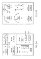
- FIG. 5A is a schematic illustration of a display screen displaying a thrust requirement generated by the system of FIG. 1 ;
- FIG. 5B is a schematic illustration of a display screen displaying a thrust requirement generated by the system of FIG. 1 in an alternate manner;
- FIG. 6 is a schematic of a system for displaying control related information to an aircraft operator, according to another embodiment
- FIG. 7 is a schematic of a sound emitting unit configured for use with the system of FIG. 6 ;
- FIG. 8 is a schematic of a system for displaying control related information to an aircraft operator, according to still another embodiment
- FIG. 9 is a schematic of a system for displaying control related information to an aircraft operator, according to yet another embodiment.
- FIG. 10 is a schematic of a system for displaying control related information to an aircraft operator, according to still yet another embodiment.
- FIG. 11 is a flow diagram of a method for displaying control related information to an aircraft operator, according to an example.
- the system includes a variety of components that are configured to either detect or receive inputs that have a bearing on an amount of thrust that is needed to move an aircraft (hereinafter "thrust requirement").
- the components provide their respective inputs to a processor.
- the processor is configured to utilize the respective inputs from each of the components to calculate the thrust requirement needed to start an aircraft rolling from a dead stop, to keep an aircraft rolling at a designated speed, and to increase and/or decrease the designated speed.
- the system further includes a display unit having a display screen.
- the display unit is communicatively connected to the processor and is configured to display images on the display screen as commanded by the processor.
- the processor is configured to provide commands to the display screen to display the thrust requirement.
- one of the components may be a throttle angle sensor that is configured to detect changes in the throttle angle.
- the throttle angle sensor may also be configured to detect the rate at which the throttle angle changes (hereinafter, the "detected throttle angle change rate") and to provide the throttle angle change rate to the processor.
- the processor is configured to utilize the respective inputs from each of the components discussed above to calculate an appropriate rate at which the aircraft operator should change the throttle angle to consume the least amount of fuel during the transition from one throttle setting to another (hereinafter, the "appropriate throttle angle change rate").
- the processor is configured to compare the detected throttle angle change rate with the appropriate throttle angle change rate and, when a difference is detected, the processor is further configured to provide a warning to the aircraft operator as the aircraft operator repositions the throttle to the displayed throttle setting.
- FIG. 1 is a schematic of a system 20 for displaying control related information to an aircraft operator, according to an embodiment.
- System 20 may be configured to be mounted or otherwise attached and integrated into any type of fixed wing aircraft including jet aircraft and propeller driven aircraft.
- System 20 may include an operator input unit 22, a data storage unit 24, an aircraft sensor 26, a display unit 28, an autothrottle 29, and a processor 30.
- Operator input unit 22 may be any type of apparatus, machine, system, sub-system or device that is configured to receive human inputs and to convert such inputs into an electronic signal.
- operator input unit 22 may be an alpha numeric keyboard, a mouse, a trackball, a touch screen, a tablet and stylus, a button, a switch, a knob, a slide, a microphone, a camera, a motion detector, a touch screen, a heat sensor or any other device that is configured to permit a human to provide inputs into an electronic system including a company sent data link.
- operator input unit 22 may comprise only a single component. In other embodiments, operator input unit 22 may comprise a plurality of components acting in concert.
- operator input unit 22 may be a self contained or independent system, such as a flight management system, that is, itself, configured to receive inputs from the aircraft operator and which, as part of its functioning, provides outputs which are received as inputs by system 20.
- operator input unit 22 may be dedicated for use exclusively with system 20 while in other embodiments, operator input unit 22 may be shared with other systems on board the aircraft.
- Data storage unit 24 may be any type of electronic memory device that is configured to store data.
- data storage unit 24 may include, without limitation, non-volatile memory, disk drives, tape drives, and mass storage devices and may include any suitable software, algorithms and/or sub-routines that provide the data storage component with the capability to store, organize, and permit retrieval of data.
- data storage unit 24 may comprise only a single component.
- data storage unit 24 may comprise a plurality of components acting in concert.
- data storage unit 24 may be dedicated for use exclusively with system 20 while in other embodiments, data storage unit 24 may be shared with other systems on board the aircraft.
- Aircraft sensor 26 may be any type of sensor including, but not limited to, any type of electronic, mechanical, and/or electromechanical device that is mounted on the aircraft and that is configured to detect a condition or circumstance of the aircraft or a condition or circumstance of the environment in which the aircraft is located.
- aircraft sensor 26 may comprise only a single component.
- aircraft sensor 26 may comprise a plurality of components acting in concert.
- aircraft sensor 26 may be dedicated for use exclusively with system 20 while in other embodiments, aircraft sensor 26 may be shared with other systems on board the aircraft.
- Display unit 28 may be any sort or type of display system that is configured to depict graphic images and/or text.
- display unit 28 may include a display screen while in other embodiments, display unit 28 may include holographic projectors.
- suitable display systems include, but are not limited to, a Cathode Ray Tube (CRT) display device, a flat panel display device, a Liquid Crystal Display (LCD) device, a thin film transistor (TFT) display device, a plasma display device, an electro-luminescent display device, a Light Emitting Diode (LED) display device, a holographic display device such as a Heads Up Display (HUD), a Micro Mirror Device (MMD) display device, electromechanical device or the like.
- CTR Cathode Ray Tube
- LCD Liquid Crystal Display
- TFT thin film transistor
- LED Light Emitting Diode
- holographic display device such as a Heads Up Display (HUD), a Micro Mirror Device (MMD) display device, electromechanical device or the like.
- display unit 28 may comprise only a single component. In other embodiments, display unit 28 may comprise a plurality of components acting in concert. In some embodiments, display unit 28 may be dedicated for use exclusively with system 20 while in other embodiments, display unit 28 may be shared with other systems on board the aircraft.
- Autothrottle 29 may be any type of mechanism that is configured to control the engines of the aircraft so as to increase and/or decrease thrust without direct control by the aircraft operator.
- Autothrottle 29 may include an independent processor, electromechanical servo motors, and any other mechanism and/or component necessary to allow autothrottle 29 to receive commands from processor 30 and to act on such commands.
- Processor 30 may be any type of computer, computer system, microprocessor, controller or other machine that is configured to perform algorithms, to execute software applications, to execute sub-routines and/or to be loaded with and to execute any other type of computer program.
- processor 30 may comprise only a single component.
- processor 30 may comprise a plurality of components acting in concert.
- processor 30 may be dedicated for use exclusively with system 20 while in other embodiments, processor 30 may be shared with other systems on board the aircraft.
- Processor 30 is communicatively connected to operator input unit 22, data storage unit 24, aircraft sensor 26, display unit 28, and autothrottle 29, in accordance with an embodiment. Such connection may be effected through the use of any suitable means of transmission including both wired and wireless connections.
- each component may be physically connected to processor 30 via a coaxial cable or via any other type of wire connection effective to convey signals.
- processor 30 is directly communicatively connected to each of the other components.
- each component may be communicatively connected to processor 30 across a vehicle bus.
- each component may be wirelessly connected to processor 30 via a Bluetooth connection, a WiFi connection, an infrared connection, or the like.
- processor 30 Being communicatively connected provides a pathway for the transmission of commands, instructions, interrogations and other signals between processor 30 and each of the other components. Through this communicative connection, processor 30 may control and/or communicate with each of the other components.
- processor 30 may control and/or communicate with each of the other components.
- Each of the other components discussed above are configured to interface and engage with processor 30 as discussed in detail below.
- FIG. 2 is a schematic of operator input unit 22 configured for use with system 20 of FIG. 1 .
- operator input unit 22 is configured to receive inputs from the aircraft operator and may be used to input information into system 20 that will have an impact on the aircraft's thrust requirement (hereinafter, "thrust related information 32").
- Thrust related information 32 may include, but is not limited to, a desired taxi speed and a maximum taxi speed. Thrust related information 32 may also include the gross weight of the aircraft. Thrust related information 32 may also include a pathway surface condition.
- Thrust related information 32 may also include a pathway surface friction coefficient which may be available from data bases, ground controllers, airport publications, or any other suitable source. Thrust related information 32 may also include tire conditions (e.g.
- operator input unit 22 is configured to automatically provide thrust related information 32 to processor 30 via the communicative connection between these two components.
- operator input unit 22 may receive an interrogation from processor 30 seeking thrust related information 32 and may be configured to provide thrust related information 32 only in response to such interrogations.
- FIG. 3 is a schematic of data storage unit 24 configured for use with system 20 of FIG. 1 .
- data storage unit 24 may be any type of electronic memory device that is configured to store data.
- data storage unit 24 is configured to store aircraft data 34 and airport data 36.
- aircraft data refers to information pertaining to an aircraft that is employing system 20.
- airport data refers to an airport at which an aircraft employing system 20 is located.
- data storage unit 24 may store aircraft data 34 for multiple types of aircraft and airport data 36 for multiple airports.
- Aircraft data 34 may include an identification of the aircraft employing system 20, such as its make, model, owner and/or operator. Aircraft data 34 may also include information about the type of engine and the number of such engines that the aircraft is equipped with. Aircraft data 34 may also include information pertaining to the thrust curve correlated with revolutions per minute ("rpm") for each engine of the aircraft. Aircraft data 34 may also include a fuel consumption rate correlated with rpms for each engine of the aircraft. Aircraft data 34 may also include a fuel consumption rate for each engine of the aircraft correlated with the rate of change of the engine's rpms, thrust curve per EPR and fuel consumption rate per EPR.
- rpm revolutions per minute
- Airport data 36 may include an identification of the airport where the aircraft employing system 20 is located. This information may be provided to data storage unit 24 by another onboard system, such as a GPS navigation system or by an inertial navigation system, or the like which may be communicatively connected to data storage unit 24. Airport data 36 may also include the type of material used to construct each pathway surface at the airport where the aircraft employing system 20 is presently located. Airport data 36 may also include grade (i.e., slope, slant and/or incline) for each pathway surface at the airport where the aircraft is presently located. Airport data 36 may also include a maximum taxi speed for the airport, the maximum gross weight per taxiway or ramp segment (ability of surface to carry weight), thrust sensitive areas, wing tip clearance areas, and airport diagrams (charts of airport showing ramp, taxiway and runway layouts).
- Aircraft data 34 and airport data 36 will have an impact on the aircraft's thrust requirement and therefore may be useful to processor 30 when calculating the aircraft's thrust requirement. Accordingly, in an embodiment, data storage unit 24 is configured to automatically provide aircraft data 34 and airport data 36 to processor 30 via the communicative connection between these two components. In other embodiments, data storage unit 24 may receive an interrogation from processor 30 seeking aircraft data 34 and airport data 36 and may be configured to provide such data only in response to such interrogations.
- FIG. 4 is a schematic of aircraft sensor 26 configured for use with the system of FIG. 1 .
- Aircraft sensor 26 may be any one or more of a wide variety of sensors mounted onboard an aircraft. Each sensor type is configured to sense an aircraft condition 27.
- aircraft sensor 26 may comprise a throttle angle sensor that is configured to monitor the aircraft's throttle and to detect any change in the throttle angle. A change in the throttle angle would be indicative of an increase or a decrease in fuel flow to the aircraft's engines and a corresponding increase or decrease in the aircraft engine's thrust.
- aircraft sensor 26 may comprise an engine rpm sensor configured to monitor the aircraft engine's rpms and to detect changes therein.
- aircraft sensor 26 may comprise an engine pressure ratio sensor configured to monitor the aircraft engine's pressure ratio and to detect changes therein.
- aircraft sensor 26 may comprise an aircraft weight sensor that is configured to detect/determine the weight of the aircraft employing system 20, and to detect changes therein such as may occur during flight (i.e., consumption of fuel) or on the ground (offloading of cargo and/or passengers).
- aircraft sensor 26 may comprise an outside air temperature sensor that is configured to detect the air temperature in the vicinity of the aircraft.
- aircraft sensor 26 may comprise a position determining unit that is configured to determine the position of the aircraft with respect to the surface of the earth.
- aircraft sensor 26 may comprise an inclinometer that is configured to determine the current incline of a ramp or other surface the aircraft is located on.
- Aircraft sensor(s) 26 will detect conditions, settings, and circumstances that will have an impact on the aircraft's thrust requirement and which therefore may be useful to processor 30 when calculating the aircraft's thrust requirement. Accordingly, in an embodiment, aircraft sensor(s) 26 is configured to automatically provide the information it has sensed/detected to processor 30 via the communicative connection between these two components. In other embodiments, aircraft sensor(s) 26 may receive an interrogation from processor 30 seeking the sensed/detected information and may be configured to provide such data only in response to such interrogations.
- system 20 works as follows. An aircraft operator enters thrust related information 32 into operator input unit 22.
- operator input unit 22 automatically provides thrust related information 32 to processor 30 and this initiates operation of system 20.
- the aircraft operator may need to actuate a switch or take some other action after entering thrust related information 32 in order to initiate operation of system 20.
- Processor 30 may then obtain aircraft data 34 and airport data 36 from data storage unit 24 and aircraft condition 27 from aircraft sensor 26.
- processor 30 may have already obtained aircraft data 34, airport data 36 and aircraft condition 27 prior to the aircraft operator entering thrust related information 32 into operator input unit 22.
- Processor 30 is configured to utilize thrust related information 32, aircraft data 34, airport data 36, and aircraft condition 27 to calculate a first thrust requirement 38.
- Processor 30 may perform the calculation by executing or otherwise utilizing any of a variety of software applications that have been written to permit the calculation of a thrust requirement based on thrust related information 32, aircraft data 34, airport data 36, and aircraft condition 27, as well as other factors.
- the first thrust requirement corresponds to a breakaway thrust for the aircraft,.
- the breakaway thrust may be calculated to include some amount of overpowering of the aircraft's engines in order to overcome factors which may not have been taken into consideration or to accommodate a margin of error in the factors that have been entered/detected.
- the breakaway thrust may correspond substantially to the least amount of thrust required to start the aircraft rolling from a dead stop without any overpowering of the aircraft's engines.
- first thrust requirement 38 will correspond to an increase or decrease in thrust to provide the acceleration or deceleration needed to achieve a user defined taxi speed.
- processor 30 is configured to provide commands to display unit 28 to display first thrust requirement 38.
- FIG. 5A is a schematic illustration of a display screen displaying first thrust requirement 38 generated by system 20 of FIG. 1 .
- the display screen of FIG. 5A comprises a portion of a conventional Flight Management System (FMS) with windows and annotations added to permit the display of first thrust requirement 38.
- FMS Flight Management System
- first thrust requirement 38 is displayed as a percentage of total available thrust.
- the letters "BT" indicate breakaway thrust. In this example, when the aircraft's engines are operated such that they produce ninety percent of their available thrust, then the aircraft should breakaway from a dead stop.
- FIG. 5B is a schematic illustration of a display screen displaying first thrust requirement 38 generated by system 20 of FIG. 1 in an alternate manner.
- the display screen of FIG. 5B comprises a portion of an aircraft's primary flight display that is used to display engine parameters.
- One of the engine parameters displayed is Interturbine Temperature (ITT), which is depicted on an analog dial.
- ITT can be either a thrust limiting parameter or a thrust setting parameter. ITT measures temperature as a correlate of thrust or power production.
- first thrust requirement 38 is displayed as a tic mark disposed along the curve of the analog dial in a position corresponding to the ITT required to generate first thrust requirement 38.
- the letters "BT" are positioned adjacent to the tic mark and indicate that the tic mark corresponds with the breakaway thrust requirement. When the arrow reaches this tic mark, then the aircraft's engines are generating enough thrust to achieve breakaway.
- these tic marks may blink, flash, strobe, pulse, change color, increase in intensity, increase in size or otherwise change in appearance to attract the attention of the aircraft operator if the power setting associated with the tic mark is exceeded.
- the primary flight display may include a trend vector that shows where the power setting will be for an associated throttle angle.
- Trend vectors are currently used in aircraft to show what an aircraft's airspeed will be at a predetermined number of seconds (e.g., six seconds) after a change in throttle angle.
- a similar indication could be provided on any or all of the engine parameters displayed on the gages illustrated in FIG. 5B . This could assist the aircraft operator in determining where to position the aircraft's throttle when attempting to match the thrust requirement indicated by system 20.
- first thrust requirement 38 may be displayed in any other suitable manner.
- suitable manners may include, but are not limited to, the use of graphics and/or alphanumerics to communicate to the aircraft operator the required engine rpms, compression ratios, pounds of thrust, and/or any other suitable engine parameter that correlates to the thrust output of an aircraft engine.
- the aircraft operator may then adjust the throttle to achieve first thrust requirement 38. To do so, the aircraft operator may watch the gage that displays the engine parameter that corresponds to first thrust requirement 38.
- the aircraft operator would observe the gage measuring thrust as a percentage of available engine thrust. When the gage reaches ninety percent, then the aircraft operator will stop adjusting the throttle and the aircraft should break away from a stop.
- the aircraft operator would observe the gage measuring ITT. When the arrow reaches the tic mark annotated with the "BT", the aircraft operator will stop adjusting the throttle and the aircraft should breakaway from a stop.
- system 20 may calculate first thrust requirement 38 and may provide commands to autothrottle 29 to adjust the throttle to produce a thrust equal to first thrust requirement 38. In this manner, the process of setting the throttle to provide first thrust requirement 38 may be automated.
- FIG. 6 is a schematic of a system 40 for displaying control related information to an aircraft operator, according to another embodiment.
- System 40 is similar to system 20, with some modifications.
- System 40 includes operator input unit 22, data storage unit 24, aircraft sensor 26, and display unit 28.
- aircraft sensor 26 comprises a throttle angle sensor 42.
- Throttle angle sensor 42 is configured to detect the current throttle angle and to also detect a detected throttle angle change rate 44.
- system 40 may also include additional aircraft sensors 26.
- System 40 also includes a processor 46.
- Processor 46 is nearly identical to processor 30, but is further configured to calculate an appropriate throttle angle change rate 48.
- Processor 46 is loaded with programming, software applications, subroutines and/or other computer code that permits it to calculate appropriate throttle angle change rate 48 using the thrust related information available from operator input unit 22, aircraft data 34, airport data 36, and the aircraft condition information provided by aircraft sensor(s) 26.
- Processor 46 is further configured to obtain detected throttle angle change rate 44 from throttle angle sensor 42 and to compare it with appropriate throttle angle change rate 48. If processor 46 determines that there is a difference between detected throttle angle change rate 44 and appropriate throttle angle change rate 48, then more fuel than necessary is being, or will be, consumed as the aircraft operator adjusts the throttle to attain first thrust requirement 38.
- Processor 46 is further configured to alert the aircraft operator to this condition.
- processor 46 may be configured to send commands to display unit 28 to display a warning.
- display unit 28 may display text, such as "SLOW DOWN THROTTLE ADJUSTMENT” or "SPEED UP THROTTLE ADJUSTMENT” or some other similar text based message.
- the difference between detected throttle angle change rate 44 and appropriate throttle angle change rate 48 may be displayed with graphical images rather than text.
- FIG. 7 is a schematic of a sound emitting unit 50 configured for use with system 40 of FIG 6 .
- Sound emitting unit 50 may comprise any apparatus, machine, device, system, or sub-system configured to emit audible sound.
- sound emitting unit 50 may comprise one or more speakers mounted in the cockpit, flight deck, or in some other location where its emissions may be audible to the aircraft operator.
- sound emitting unit 50 may be a speaker that is integrated into display unit 28.
- sound emitting unit 50 may comprise an earpiece or a headset worn by the aircraft operator.
- Sound emitting unit 50 is communicatively connected to processor 46 and is configured to receive commands therefrom.
- Processor 46 is further configured to provide commands to sound emitting unit 50 to emit a sound when processor 46 detects a difference between detected throttle angle change rate 44 and appropriate throttle angle change rate 46.
- sound emitting unit 50 may emit spoken words indicative of the need to change the rate of throttle adjustment.
- sound emitting unit 50 may emit a warning tone.
- the warning tone may have either a pitch or a volume, or both, that corresponds to the magnitude of the difference between detected throttle angle change rate 44 and appropriate throttle angle change rate 48.
- the pitch, the volume, or both may vary in a manner that corresponds with changes in the magnitude of the difference between detected throttle angle change rate 44 and appropriate throttle angle change rate 48.
- sound emitting unit 50 may discontinue emitting sound. In this manner, system 40 provides the aircraft operator with real time feedback as the throttle is adjusted.
- FIG. 8 is a schematic of a system 52 for displaying control related information to an aircraft operator, according to still another embodiment.
- System 52 is similar to system 20, with some modifications.
- System 52 includes operator input unit 22, data storage unit 24, aircraft sensor 26, and display unit 28.
- System 52 also includes a processor 54.
- Processor 54 is nearly identical to processor 30, but is further configured to calculate an additional thrust requirement.
- an aircraft operator may use operator input unit 22 to input a desired taxi speed. For example, an aircraft operator may input twenty knots as the desired taxi speed. This situation is illustrated in FIG. 5A . There, the aircraft operator has entered the number "twenty" in a window 58 provided by the flight management system. In the illustrated example, window 58 is annotated with the letters "TS" to associate window 58 with the desired taxi speed.
- Operator input unit 22 provides the desired taxi speed to processor 54 together with other items of thrust related information.
- Processor 54 is configured to calculate a second thrust requirement 56 using the taxi speed together with any other items of thrust related information provided by operator input unit 22, aircraft data 34, airport data 36, and any aircraft condition information provided by sensor(s) 26.
- Second thrust requirement 56 corresponds with the thrust required to achieve and maintain the desired taxi speed, in an embodiment.
- second thrust requirement 56 be calculated to include some amount of overpowering of the aircraft's engines in order to overcome factors which may not have been taken into consideration or to accommodate a margin of error in the factors that have been entered/detected.
- second thrust requirement 56 may correspond substantially to the least amount of thrust required to maintain the desired taxi speed without any overpowering of the aircraft's engines.
- Processor 54 is further configured to provide commands to display unit 28 to display second thrust requirement 56 to the aircraft operator.
- the gage depicting ITT which is an engine parameter that correlates with thrust, includes a second tic mark labeled with the number "twenty" to illustrate the point on the gage where the aircraft's engine thrust will be sufficient to maintain the desired taxi speed of twenty knots.
- second thrust requirement 56 may be displayed in any other suitable manner.
- autothrottle 29 may be configured to set the throttle to provide enough thrust to break the aircraft away from a dead stop and then, once the aircraft has begun to move, to adjust the throttle to provide an appropriate amount of thrust necessary to allow the aircraft to attain and maintain the desired taxi speed.
- FIG. 9 is a schematic of a system 60 for displaying control related information to an aircraft operator, according to yet another embodiment.
- System 60 is similar to system 20 and system 52, with some modifications.
- System 60 includes operator input unit 22, data storage unit 24, aircraft sensor 26, and display unit 28.
- System 60 further includes a communication unit 62.
- Communication unit 62 may be any type of communication device that is configured to receive wireless communications.
- communication unit 62 may be configured to receive satellite communication transmissions, microwave transmissions or any other type of RF transmissions.
- communication unit 62 cooperates with an antenna 64 to detect and receive such wireless communication signals.
- Communication unit 62 may include associated electronics to process the received signals.
- communication unit 62 may be configured to receive data link transmissions from ground controllers.
- communication unit 62 may be dedicated for use exclusively with system 60 while in other embodiments communication unit 62 may be shared with other systems on board the aircraft.
- System 60 also includes a processor 66.
- Processor 66 is nearly identical to processor 30 or processor 54, but is further configured to calculate a third thrust requirement 68.
- communication unit 62 is communicatively connected to processor 66.
- Communication unit 62 is further configured to receive a wireless signal 70 from a source external to the aircraft.
- wireless signal 70 may be sent by a ground controller to the aircraft employing system 60 and may contain a controller defined taxi speed.
- Communication unit 62 is further configured to provide wireless signal 70 to processor 66, in an embodiment.
- Processor 54 is configured to extract the controller defined taxi speed from wireless signal 70.
- Processor 54 is further configured to calculate third thrust requirement 68 using the thrust related information provided by operator input unit 22, aircraft data 34, airport data 36, any aircraft condition information provided by sensor(s) 26 and the controller defined taxi speed provided by communication unit 62.
- Third thrust requirement 68 corresponds with the thrust required to achieve and maintain the controller defined taxi speed, in an embodiment.
- Processor 66 may be further configured to provide commands to display unit 28 to display third thrust requirement 68 in generally the same manner as that discussed with reference to second thrust requirement 56. In some embodiments of system 60, processor 66 may be configured to provide commands to display unit 28 to stop displaying second thrust requirement 56 when wireless signal 70 is received or once third thrust requirement 68 has been calculated.
- third thrust requirement 68 be calculated to include some amount of overpowering of the aircraft's engines in order to overcome factors which may not have been taken into consideration or to accommodate a margin of error in the factors that have been entered/detected. In other embodiments, third thrust requirement 68 may correspond substantially to the least amount of thrust required to maintain the controller defined taxi speed without substantially any overpowering of the aircraft's.
- autothrottle 29 may be configured to set the throttle to provide enough thrust to break the aircraft away from a dead stop and then, once the aircraft has begun to move, to adjust the throttle to provide an appropriate amount of thrust necessary to allow the aircraft to attain and maintain the controlled defined taxi speed. In this manner, autothrottle 29 may facilitate at least a partial remote control of the aircraft by ground controllers.
- FIG. 10 is a schematic of a system 72 for displaying control related information to an aircraft operator, according to still yet another embodiment.
- System 72 combines the functionality of system 40 (illustrated in FIG. 6 ) with the functionality of system 52 (illustrated in FIG. 8 ).
- System 72 includes operator input unit 22, data storage unit 24, aircraft sensor 26, display unit 28 and sound emitting unit 50.
- Aircraft sensor 26 comprises throttle angle sensor 42 which is configured to detect detected throttle angle change rate 44.
- System 72 further includes a processor 74 which is nearly identical to processor 30, but which is further configured to calculate second thrust requirement 56 in the same manner as discussed above with reference to FIG. 8 and to calculate appropriate throttle angle change rate 48 in the same manner as discussed above with reference to FIG. 6 .
- Processor 74 is still further configured to provide commands to display unit 28 to display second thrust requirement 56 in the same manner as discussed above with reference to FIG. 8 .
- Processor 74 is still further configured to alert an aircraft operator when there is a difference between detected throttle angle change rate 44 and appropriate throttle angle change rate 48 through the providing of commands to either display unit 28 or to sound emitting unit 50, in the same manner discussed above with reference to FIG. 6 .
- aircraft sensor 26 may comprise a movement detection system such as a GPS navigation system or an inertial navigation system, or some other system configured to determine movement of the aircraft.
- the movement information provided by the movement system may be correlated with the thrust output by the aircraft's engines as the aircraft taxis or breaks away from a stop. This information may be interpolated, extrapolated or otherwise interpreted in a manner by any or all of the systems discussed above to predict what a thrust requirement would be for a particular task.
- the system utilizing the movement detection system may be configured to use these two data points to predict a thrust requirement for any taxi speed along the pathway surface.
- Such a system may enhance the accuracy of any of the above described systems to calculate thrust requirements or, in some circumstances, may eliminate the need for some of the components or the need for some of the information required by the above described systems.
- FIG. 11 is a flow diagram of a method for displaying control related information to an aircraft operator, according to an example.
- thrust related information may include, but is not limited to, a desired taxi speed, a maximum taxi speed, an aircraft weight, a pathway surface condition, a pathway surface friction value, a tire condition and a weather condition.
- Aircraft data may include, but is not limited to, an identification of the type of aircraft under consideration, the type of engine utilized by the aircraft, the thrust curve for the engine or engines correlated with engine rpm (or with some other engine parameter), the fuel consumption rate correlated with engine rpm (or with some other engine parameter), and the fuel consumption rate per RPM change rate.
- Airport data is received.
- Airport data may included an identification of the airport under consideration, the type of material used to construct each pathway surface, the grade of each pathway surface and any airport imposed maximum taxi speed.
- aircraft conditions are received.
- the aircraft conditions include, but are not limited to, the angle of the throttle, the current rpm state of the engine(s), the engine pressure ratio, the current aircraft weight, and an outside air temperature.
- the thrust related information, the aircraft data, the airport data and the aircraft conditions are utilized to calculate a thrust requirement needed to either break the aircraft away from a dead stop or the thrust needed to achieve and/or maintain a desired taxi speed. In some examples, both will be calculated.
- the thrust requirement calculated at block 78 will be displayed to an aircraft operator.
- the thrust requirement may be displayed in any suitable manner and may include information correlating to any commonly used engine output metric, such as pounds of thrust, rpms, pressure ratios, and the like.
- the pilot may then adjust the throttle to achieve the calculated thrust requirement.
- the above system provides numerous advantages over existing practice by taking much of the guess work out of throttle control for the taxi stage of an aircraft's flight.
- the overpowering of an aircraft's engines can be avoided. This, in turn, can reduce the engine's fuel consumption, emissions, engine wear and noise pollution.
- the above systems and methods further enhance the advantages over current practice.
Landscapes
- Engineering & Computer Science (AREA)
- Aviation & Aerospace Engineering (AREA)
- Traffic Control Systems (AREA)
Claims (9)
- Système (20) pour afficher des informations de commande à l'intention d'un opérateur d'aéronef, le système (20) comprenant :une unité d'affichage (28) ;une unité de stockage de données (24) conçue pour stocker des données d'aéronef (34) et des données d'aéroport (36) ;une unité d'entrée opérateur (22) conçue pour recevoir des informations de poussée (32) depuis l'opérateur d'aéronef ;un capteur d'aéronef (26) conçu pour détecter un état d'aéronef (27) ; etun processeur (30) relié à l'unité d'affichage (28), à l'unité de stockage de données (24), à l'unité d'entrée opérateur (22) et au capteur d'aéronef (26) de façon à pouvoir communiquer avec eux,lequel processeur (30) est conçu pour obtenir les données d'aéronef (34) et les données d'aéroport (36) auprès de l'unité de stockage de données (24), pour obtenir les informations de poussée (32) auprès de l'unité d'entrée opérateur (22) et pour obtenir l'état d'aéronef (27) auprès du capteur d'aéronef (26), pour calculer une première poussée nécessaire (38) correspondant à une poussée de mise en mouvement en fonction des données d'aéronef (34), des données d'aéroport (36), des informations de poussée (32) et de l'état d'aéronef (27) et pour fournir des commandes à l'unité d'affichage (28) de façon à lui faire afficher la première poussée nécessaire (38).
- Système (20) selon la revendication 1, dans lequel la première poussée nécessaire (38) comprend une poussée minimale nécessaire à la mise en mouvement.
- Système (20) selon la revendication 1, dans lequel les données d'aéronef (34) comporte au moins un des éléments suivants : un type de moteur associé à un aéronef, une courbe de poussée pour le type de moteur corrélée à un régime en tours par minute, un taux de consommation de carburant pour un moteur corrélé à un régime de moteur en tours par minute et un taux de consommation de carburant pour le moteur corrélé à un taux de variation du régime de moteur en tours par minute.
- Système (20) selon la revendication 1, dans lequel les données d'aéroport (36) comportent au moins un des éléments suivants : une identification d'un matériau de surface utilisé pour construire une surface de voie à un aéroport et une identification d'une qualité de la surface de voie à l'aéroport.
- Système (20) selon la revendication 1, dans lequel les informations de poussée (32) comprennent au moins un des éléments suivants : une vitesse de roulage souhaitée, un poids d'un aéronef, un état d'une surface de voie, une valeur de frottement pour la surface de voie, un état d'un pneu de l'aéronef et une condition météorologique aux alentours de l'aéronef.
- Système (20) selon la revendication 1, dans lequel le capteur d'aéronef (26) comprend au moins un des éléments suivants : un capteur d'angle de manette des gaz, un capteur de régime de moteur en tours par minute, un capteur de rapport de pressions moteur et un capteur de poids d'aéronef.
- Système (20) selon la revendication 1, dans lequel le capteur d'aéronef (26) comprend un capteur d'angle de manette des gaz (42) conçu pour détecter un taux de variation d'angle de manette des gaz (le taux de variation d'angle de manette des gaz détecté (44)), et dans lequel le processeur (30) est en outre conçu pour obtenir le taux de variation d'angle de manette des gaz détecté (44) auprès du capteur d'angle de manette des gaz (42), pour calculer un taux de variation d'angle de manette des gaz adapté (48) en fonction des données d'aéronef (34), des données d'aéroport (36), des informations de poussée (32) et de l'état d'aéronef (27), pour comparer le taux de variation d'angle de manette des gaz détecté (44) au taux de variation d'angle de manette des gaz adapté (48), et pour avertir l'opérateur d'aéronef si le taux de variation d'angle de manette des gaz adapté (48) est différent du taux de variation d'angle de manette des gaz détecté (44).
- Système (52) selon la revendication 1, dans lequel le processeur (54) est en outre conçu pour calculer une deuxième poussée nécessaire (56) en fonction des données d'aéronef (34), des données d'aéroport (36), des informations de poussée (32) et de l'état d' aéronef (27), et pour fournir des commandes à l'unité d'affichage (28) de façon à lui faire afficher la deuxième poussée nécessaire (56).
- Système (52) selon la revendication 8, dans lequel la deuxième poussée nécessaire (56) correspond à une poussée nécessaire au maintien de la vitesse de roulage souhaitée.
Applications Claiming Priority (1)
| Application Number | Priority Date | Filing Date | Title |
|---|---|---|---|
| US12/705,865 US8090483B2 (en) | 2010-02-15 | 2010-02-15 | System and method for displaying control related information to an aircraft operator |
Publications (3)
| Publication Number | Publication Date |
|---|---|
| EP2357134A2 EP2357134A2 (fr) | 2011-08-17 |
| EP2357134A3 EP2357134A3 (fr) | 2012-03-28 |
| EP2357134B1 true EP2357134B1 (fr) | 2013-04-17 |
Family
ID=44012418
Family Applications (1)
| Application Number | Title | Priority Date | Filing Date |
|---|---|---|---|
| EP11151925.2A Active EP2357134B1 (fr) | 2010-02-15 | 2011-01-24 | Procédé et système pour afficher les informations relatives au contrôle pour un pilote d'avion |
Country Status (3)
| Country | Link |
|---|---|
| US (1) | US8090483B2 (fr) |
| EP (1) | EP2357134B1 (fr) |
| CN (1) | CN102167164B (fr) |
Families Citing this family (27)
| Publication number | Priority date | Publication date | Assignee | Title |
|---|---|---|---|---|
| US20070142980A1 (en) * | 2005-12-19 | 2007-06-21 | Marc Ausman | Avionics method and apparatus |
| US8473123B2 (en) * | 2010-02-18 | 2013-06-25 | Massachusetts Institute Of Technology | Programmable surface |
| FR2970093B1 (fr) * | 2011-01-05 | 2013-12-13 | Airbus Operations Sas | Procede et dispositif de surveillance automatique d'operations aeriennes necessitant une garantie de performance de navigation et de guidage. |
| US9013330B2 (en) * | 2011-09-01 | 2015-04-21 | Honeywell International Inc. | Electric taxi system guidance |
| US9485236B2 (en) | 2012-11-14 | 2016-11-01 | Verifyme, Inc. | System and method for verified social network profile |
| US9250660B2 (en) | 2012-11-14 | 2016-02-02 | Laserlock Technologies, Inc. | “HOME” button with integrated user biometric sensing and verification system for mobile device |
| CN103057711B (zh) * | 2012-12-04 | 2016-09-21 | 中国商用飞机有限责任公司 | 用于控制飞机的额外起飞推力的方法和装置 |
| US20140306837A1 (en) * | 2013-02-13 | 2014-10-16 | Veedims, Llc | System and method for qualitative indication of cumulative wear status |
| EP2971704B1 (fr) | 2013-03-14 | 2017-08-23 | Rolls-Royce North American Technologies, Inc. | Interface de configuration de moteur à turbine à gaz |
| US9377325B2 (en) * | 2013-03-18 | 2016-06-28 | Honeywell International Inc. | System and method for graphically displaying airspace speed data |
| CN103237138B (zh) * | 2013-03-21 | 2015-12-02 | 陕西飞机工业(集团)有限公司 | 一种机内通话系统二线检测仪 |
| US9108739B2 (en) * | 2013-05-03 | 2015-08-18 | The Boeing Company | Taxiing aircraft vicinity visualization system and method |
| US9457899B2 (en) * | 2013-06-24 | 2016-10-04 | The Boeing Company | Modular vehicle lift system |
| US9234743B2 (en) | 2014-01-16 | 2016-01-12 | Sikorsky Aircraft Corporation | Tip clearance measurement |
| US9614800B1 (en) * | 2014-01-17 | 2017-04-04 | Rockwell Collins, Inc. | Threaded datalink message display |
| US9457896B2 (en) | 2014-01-24 | 2016-10-04 | Honeywell International Inc. | Electric taxi system with speed control (ETSSC) |
| US10665114B2 (en) * | 2014-03-28 | 2020-05-26 | The Boeing Company | Aircraft fuel optimization analytics |
| US9567100B2 (en) * | 2014-04-22 | 2017-02-14 | Honeywell International Inc. | E-Taxi predictive performance system |
| US20160068277A1 (en) * | 2014-07-08 | 2016-03-10 | Salvatore Manitta | Unmanned Aircraft Systems Ground Support Platform |
| US9545995B1 (en) * | 2015-07-14 | 2017-01-17 | Qualcomm Incorporated | Control normalization for unmanned autonomous systems |
| WO2017195133A1 (fr) | 2016-05-11 | 2017-11-16 | Bombardier Inc. | Procédé et système pour afficher une entrée de commande d'aéronef |
| US10235892B1 (en) * | 2017-05-05 | 2019-03-19 | Architecture Technology Corporation | Aircraft surface state event track system and method |
| WO2018227623A1 (fr) * | 2017-06-16 | 2018-12-20 | 深圳市大疆创新科技有限公司 | Procédé de commande, système d'aéronef et terminal d'affichage |
| CN112985497B (zh) * | 2021-02-09 | 2024-12-27 | 邯郸市晔创节能科技有限公司 | 近地低空飞行器运动状态的监测系统及方法 |
| US12399507B2 (en) * | 2021-11-15 | 2025-08-26 | Beta Air Llc | Systems and methods for controlling a flight boundary of an aircraft |
| EP4230981A1 (fr) * | 2022-02-16 | 2023-08-23 | The Boeing Company | Système et procédé permettant de déterminer la poussée du moteur d'un aéronef roulant au sol |
| CN115447791B (zh) * | 2022-10-11 | 2025-05-23 | 中国航空工业集团公司西安飞机设计研究所 | 一种飞机自动油门推力控制方法及装置 |
Family Cites Families (10)
| Publication number | Priority date | Publication date | Assignee | Title |
|---|---|---|---|---|
| US4325123A (en) * | 1978-07-28 | 1982-04-13 | The Boeing Company | Economy performance data avionic system |
| US5048285A (en) * | 1990-03-26 | 1991-09-17 | Untied Technologies Corporation | Control system for gas turbine engines providing extended engine life |
| EP0750238B1 (fr) * | 1995-06-20 | 2000-03-01 | Honeywell Inc. | Système intégré d'anti-collision avec le sol |
| US6092009A (en) * | 1995-07-31 | 2000-07-18 | Alliedsignal | Aircraft terrain information system |
| CN1742277B (zh) * | 2001-12-04 | 2010-05-12 | 通用电气航空系统有限责任公司 | 飞机滑行规划系统和方法 |
| US6751545B2 (en) * | 2001-12-04 | 2004-06-15 | Smiths Aerospace, Inc. | Aircraft taxi planning system and method |
| US6928363B2 (en) * | 2002-09-20 | 2005-08-09 | The Boeing Company | Autotiller control system for aircraft |
| US8255098B2 (en) * | 2007-10-17 | 2012-08-28 | The Boeing Company | Variably manned aircraft |
| FR2931983B1 (fr) * | 2008-06-02 | 2018-04-06 | Airbus Operations | Methode et systeme de gestion automatique d'un convoi d'aeronefs roulant au sol. |
| US20100153875A1 (en) * | 2008-12-16 | 2010-06-17 | O'flynn Mark James | Air traffic control apparatus and air traffic control information processing method |
-
2010
- 2010-02-15 US US12/705,865 patent/US8090483B2/en active Active
-
2011
- 2011-01-24 EP EP11151925.2A patent/EP2357134B1/fr active Active
- 2011-02-14 CN CN201110078049.5A patent/CN102167164B/zh active Active
Also Published As
| Publication number | Publication date |
|---|---|
| EP2357134A2 (fr) | 2011-08-17 |
| US20110202205A1 (en) | 2011-08-18 |
| CN102167164B (zh) | 2015-12-02 |
| US8090483B2 (en) | 2012-01-03 |
| EP2357134A3 (fr) | 2012-03-28 |
| CN102167164A (zh) | 2011-08-31 |
Similar Documents
| Publication | Publication Date | Title |
|---|---|---|
| EP2357134B1 (fr) | Procédé et système pour afficher les informations relatives au contrôle pour un pilote d'avion | |
| EP3378784B1 (fr) | Système et procédé d'optimisation d'économie de carburant d'aéronef en temps réel | |
| CN111046097B (zh) | 可适应的交通工具监视系统 | |
| EP2360648A1 (fr) | Procédé et système de prédiction de la performance d'un avion | |
| EP2660563B1 (fr) | Système et procédé pour une utilisation économique d'un aéronef | |
| EP2565861B1 (fr) | Guidage de système de taxi électrique | |
| CN101384972B (zh) | 用于预测飞行器在着陆跑道上完全停止的可能性的方法和系统 | |
| US8676399B2 (en) | System and method for generating and displaying an electric taxi index | |
| US20140136028A1 (en) | Avionics Method and Apparatus | |
| US10831198B2 (en) | Process and machine for making a runway extension speed for an aircraft | |
| US9815567B2 (en) | Aircraft speed guidance display | |
| US7647140B2 (en) | System for aiding the piloting of an aircraft during the approach to a runway with a view to a landing | |
| US20030229426A1 (en) | Method and system for autoflight information display | |
| US20110040431A1 (en) | Automated take off control system and method | |
| CN109478374A (zh) | 飞行器控制系统 | |
| US20240166363A1 (en) | Non-intrusive flight data collection and analyzation with flight automation | |
| US8548653B2 (en) | Method and system for aiding the piloting of an airplane during an approach | |
| US20130238173A1 (en) | Methods for derated thrust visualization | |
| JP6457923B2 (ja) | 下降アルゴリズムを実行する航空機電子機器を使用して航空機の下降段階を自動的に制御する方法 | |
| EP3296698A2 (fr) | Système et procédé permettant de déterminer et d'afficher le niveau d'énergie d'aéronef optimisé | |
| US11630836B2 (en) | Matched array flight alignment system and method | |
| JP2016164060A5 (fr) | ||
| US8674851B2 (en) | Method and device for displaying trim information on an airplane during a take-off | |
| US8723693B1 (en) | System for and method of indicating predictive windshear transmitter status | |
| US11842650B2 (en) | Device and method for determining a safe aircraft runway distance |
Legal Events
| Date | Code | Title | Description |
|---|---|---|---|
| PUAI | Public reference made under article 153(3) epc to a published international application that has entered the european phase |
Free format text: ORIGINAL CODE: 0009012 |
|
| 17P | Request for examination filed |
Effective date: 20110124 |
|
| AK | Designated contracting states |
Kind code of ref document: A2 Designated state(s): AL AT BE BG CH CY CZ DE DK EE ES FI FR GB GR HR HU IE IS IT LI LT LU LV MC MK MT NL NO PL PT RO RS SE SI SK SM TR |
|
| AX | Request for extension of the european patent |
Extension state: BA ME |
|
| PUAL | Search report despatched |
Free format text: ORIGINAL CODE: 0009013 |
|
| AK | Designated contracting states |
Kind code of ref document: A3 Designated state(s): AL AT BE BG CH CY CZ DE DK EE ES FI FR GB GR HR HU IE IS IT LI LT LU LV MC MK MT NL NO PL PT RO RS SE SI SK SM TR |
|
| AX | Request for extension of the european patent |
Extension state: BA ME |
|
| RIC1 | Information provided on ipc code assigned before grant |
Ipc: G08G 5/06 20060101ALI20120221BHEP Ipc: B64D 31/00 20060101AFI20120221BHEP |
|
| 17Q | First examination report despatched |
Effective date: 20120314 |
|
| GRAP | Despatch of communication of intention to grant a patent |
Free format text: ORIGINAL CODE: EPIDOSNIGR1 |
|
| GRAS | Grant fee paid |
Free format text: ORIGINAL CODE: EPIDOSNIGR3 |
|
| GRAA | (expected) grant |
Free format text: ORIGINAL CODE: 0009210 |
|
| AK | Designated contracting states |
Kind code of ref document: B1 Designated state(s): AL AT BE BG CH CY CZ DE DK EE ES FI FR GB GR HR HU IE IS IT LI LT LU LV MC MK MT NL NO PL PT RO RS SE SI SK SM TR |
|
| REG | Reference to a national code |
Ref country code: GB Ref legal event code: FG4D |
|
| REG | Reference to a national code |
Ref country code: CH Ref legal event code: EP |
|
| REG | Reference to a national code |
Ref country code: IE Ref legal event code: FG4D |
|
| REG | Reference to a national code |
Ref country code: AT Ref legal event code: REF Ref document number: 607121 Country of ref document: AT Kind code of ref document: T Effective date: 20130515 |
|
| REG | Reference to a national code |
Ref country code: DE Ref legal event code: R096 Ref document number: 602011001333 Country of ref document: DE Effective date: 20130613 |
|
| REG | Reference to a national code |
Ref country code: AT Ref legal event code: MK05 Ref document number: 607121 Country of ref document: AT Kind code of ref document: T Effective date: 20130417 |
|
| REG | Reference to a national code |
Ref country code: LT Ref legal event code: MG4D |
|
| REG | Reference to a national code |
Ref country code: NL Ref legal event code: VDEP Effective date: 20130417 |
|
| PG25 | Lapsed in a contracting state [announced via postgrant information from national office to epo] |
Ref country code: LT Free format text: LAPSE BECAUSE OF FAILURE TO SUBMIT A TRANSLATION OF THE DESCRIPTION OR TO PAY THE FEE WITHIN THE PRESCRIBED TIME-LIMIT Effective date: 20130417 Ref country code: SE Free format text: LAPSE BECAUSE OF FAILURE TO SUBMIT A TRANSLATION OF THE DESCRIPTION OR TO PAY THE FEE WITHIN THE PRESCRIBED TIME-LIMIT Effective date: 20130417 Ref country code: GR Free format text: LAPSE BECAUSE OF FAILURE TO SUBMIT A TRANSLATION OF THE DESCRIPTION OR TO PAY THE FEE WITHIN THE PRESCRIBED TIME-LIMIT Effective date: 20130718 Ref country code: ES Free format text: LAPSE BECAUSE OF FAILURE TO SUBMIT A TRANSLATION OF THE DESCRIPTION OR TO PAY THE FEE WITHIN THE PRESCRIBED TIME-LIMIT Effective date: 20130728 Ref country code: BE Free format text: LAPSE BECAUSE OF FAILURE TO SUBMIT A TRANSLATION OF THE DESCRIPTION OR TO PAY THE FEE WITHIN THE PRESCRIBED TIME-LIMIT Effective date: 20130417 Ref country code: PT Free format text: LAPSE BECAUSE OF FAILURE TO SUBMIT A TRANSLATION OF THE DESCRIPTION OR TO PAY THE FEE WITHIN THE PRESCRIBED TIME-LIMIT Effective date: 20130819 Ref country code: FI Free format text: LAPSE BECAUSE OF FAILURE TO SUBMIT A TRANSLATION OF THE DESCRIPTION OR TO PAY THE FEE WITHIN THE PRESCRIBED TIME-LIMIT Effective date: 20130417 Ref country code: SI Free format text: LAPSE BECAUSE OF FAILURE TO SUBMIT A TRANSLATION OF THE DESCRIPTION OR TO PAY THE FEE WITHIN THE PRESCRIBED TIME-LIMIT Effective date: 20130417 Ref country code: NO Free format text: LAPSE BECAUSE OF FAILURE TO SUBMIT A TRANSLATION OF THE DESCRIPTION OR TO PAY THE FEE WITHIN THE PRESCRIBED TIME-LIMIT Effective date: 20130717 Ref country code: IS Free format text: LAPSE BECAUSE OF FAILURE TO SUBMIT A TRANSLATION OF THE DESCRIPTION OR TO PAY THE FEE WITHIN THE PRESCRIBED TIME-LIMIT Effective date: 20130817 Ref country code: AT Free format text: LAPSE BECAUSE OF FAILURE TO SUBMIT A TRANSLATION OF THE DESCRIPTION OR TO PAY THE FEE WITHIN THE PRESCRIBED TIME-LIMIT Effective date: 20130417 |
|
| PG25 | Lapsed in a contracting state [announced via postgrant information from national office to epo] |
Ref country code: BG Free format text: LAPSE BECAUSE OF FAILURE TO SUBMIT A TRANSLATION OF THE DESCRIPTION OR TO PAY THE FEE WITHIN THE PRESCRIBED TIME-LIMIT Effective date: 20130717 Ref country code: RS Free format text: LAPSE BECAUSE OF FAILURE TO SUBMIT A TRANSLATION OF THE DESCRIPTION OR TO PAY THE FEE WITHIN THE PRESCRIBED TIME-LIMIT Effective date: 20130417 Ref country code: PL Free format text: LAPSE BECAUSE OF FAILURE TO SUBMIT A TRANSLATION OF THE DESCRIPTION OR TO PAY THE FEE WITHIN THE PRESCRIBED TIME-LIMIT Effective date: 20130417 Ref country code: LV Free format text: LAPSE BECAUSE OF FAILURE TO SUBMIT A TRANSLATION OF THE DESCRIPTION OR TO PAY THE FEE WITHIN THE PRESCRIBED TIME-LIMIT Effective date: 20130417 Ref country code: HR Free format text: LAPSE BECAUSE OF FAILURE TO SUBMIT A TRANSLATION OF THE DESCRIPTION OR TO PAY THE FEE WITHIN THE PRESCRIBED TIME-LIMIT Effective date: 20130417 Ref country code: CY Free format text: LAPSE BECAUSE OF FAILURE TO SUBMIT A TRANSLATION OF THE DESCRIPTION OR TO PAY THE FEE WITHIN THE PRESCRIBED TIME-LIMIT Effective date: 20130417 |
|
| PG25 | Lapsed in a contracting state [announced via postgrant information from national office to epo] |
Ref country code: SK Free format text: LAPSE BECAUSE OF FAILURE TO SUBMIT A TRANSLATION OF THE DESCRIPTION OR TO PAY THE FEE WITHIN THE PRESCRIBED TIME-LIMIT Effective date: 20130417 Ref country code: CZ Free format text: LAPSE BECAUSE OF FAILURE TO SUBMIT A TRANSLATION OF THE DESCRIPTION OR TO PAY THE FEE WITHIN THE PRESCRIBED TIME-LIMIT Effective date: 20130417 Ref country code: EE Free format text: LAPSE BECAUSE OF FAILURE TO SUBMIT A TRANSLATION OF THE DESCRIPTION OR TO PAY THE FEE WITHIN THE PRESCRIBED TIME-LIMIT Effective date: 20130417 Ref country code: DK Free format text: LAPSE BECAUSE OF FAILURE TO SUBMIT A TRANSLATION OF THE DESCRIPTION OR TO PAY THE FEE WITHIN THE PRESCRIBED TIME-LIMIT Effective date: 20130417 |
|
| PLBE | No opposition filed within time limit |
Free format text: ORIGINAL CODE: 0009261 |
|
| STAA | Information on the status of an ep patent application or granted ep patent |
Free format text: STATUS: NO OPPOSITION FILED WITHIN TIME LIMIT |
|
| PG25 | Lapsed in a contracting state [announced via postgrant information from national office to epo] |
Ref country code: IT Free format text: LAPSE BECAUSE OF FAILURE TO SUBMIT A TRANSLATION OF THE DESCRIPTION OR TO PAY THE FEE WITHIN THE PRESCRIBED TIME-LIMIT Effective date: 20130417 Ref country code: RO Free format text: LAPSE BECAUSE OF FAILURE TO SUBMIT A TRANSLATION OF THE DESCRIPTION OR TO PAY THE FEE WITHIN THE PRESCRIBED TIME-LIMIT Effective date: 20130417 Ref country code: NL Free format text: LAPSE BECAUSE OF FAILURE TO SUBMIT A TRANSLATION OF THE DESCRIPTION OR TO PAY THE FEE WITHIN THE PRESCRIBED TIME-LIMIT Effective date: 20130417 |
|
| 26N | No opposition filed |
Effective date: 20140120 |
|
| REG | Reference to a national code |
Ref country code: DE Ref legal event code: R097 Ref document number: 602011001333 Country of ref document: DE Effective date: 20140120 |
|
| PG25 | Lapsed in a contracting state [announced via postgrant information from national office to epo] |
Ref country code: LU Free format text: LAPSE BECAUSE OF FAILURE TO SUBMIT A TRANSLATION OF THE DESCRIPTION OR TO PAY THE FEE WITHIN THE PRESCRIBED TIME-LIMIT Effective date: 20140124 |
|
| REG | Reference to a national code |
Ref country code: CH Ref legal event code: PL |
|
| PG25 | Lapsed in a contracting state [announced via postgrant information from national office to epo] |
Ref country code: LI Free format text: LAPSE BECAUSE OF NON-PAYMENT OF DUE FEES Effective date: 20140131 Ref country code: CH Free format text: LAPSE BECAUSE OF NON-PAYMENT OF DUE FEES Effective date: 20140131 |
|
| REG | Reference to a national code |
Ref country code: IE Ref legal event code: MM4A |
|
| PG25 | Lapsed in a contracting state [announced via postgrant information from national office to epo] |
Ref country code: IE Free format text: LAPSE BECAUSE OF NON-PAYMENT OF DUE FEES Effective date: 20140124 |
|
| PG25 | Lapsed in a contracting state [announced via postgrant information from national office to epo] |
Ref country code: MC Free format text: LAPSE BECAUSE OF FAILURE TO SUBMIT A TRANSLATION OF THE DESCRIPTION OR TO PAY THE FEE WITHIN THE PRESCRIBED TIME-LIMIT Effective date: 20130417 |
|
| REG | Reference to a national code |
Ref country code: FR Ref legal event code: PLFP Year of fee payment: 6 |
|
| PG25 | Lapsed in a contracting state [announced via postgrant information from national office to epo] |
Ref country code: MT Free format text: LAPSE BECAUSE OF FAILURE TO SUBMIT A TRANSLATION OF THE DESCRIPTION OR TO PAY THE FEE WITHIN THE PRESCRIBED TIME-LIMIT Effective date: 20130417 |
|
| PG25 | Lapsed in a contracting state [announced via postgrant information from national office to epo] |
Ref country code: SM Free format text: LAPSE BECAUSE OF FAILURE TO SUBMIT A TRANSLATION OF THE DESCRIPTION OR TO PAY THE FEE WITHIN THE PRESCRIBED TIME-LIMIT Effective date: 20130417 |
|
| PG25 | Lapsed in a contracting state [announced via postgrant information from national office to epo] |
Ref country code: TR Free format text: LAPSE BECAUSE OF FAILURE TO SUBMIT A TRANSLATION OF THE DESCRIPTION OR TO PAY THE FEE WITHIN THE PRESCRIBED TIME-LIMIT Effective date: 20130417 Ref country code: HU Free format text: LAPSE BECAUSE OF FAILURE TO SUBMIT A TRANSLATION OF THE DESCRIPTION OR TO PAY THE FEE WITHIN THE PRESCRIBED TIME-LIMIT; INVALID AB INITIO Effective date: 20110124 |
|
| REG | Reference to a national code |
Ref country code: FR Ref legal event code: PLFP Year of fee payment: 7 |
|
| REG | Reference to a national code |
Ref country code: FR Ref legal event code: PLFP Year of fee payment: 8 |
|
| PGFP | Annual fee paid to national office [announced via postgrant information from national office to epo] |
Ref country code: GB Payment date: 20180130 Year of fee payment: 8 |
|
| PG25 | Lapsed in a contracting state [announced via postgrant information from national office to epo] |
Ref country code: MK Free format text: LAPSE BECAUSE OF FAILURE TO SUBMIT A TRANSLATION OF THE DESCRIPTION OR TO PAY THE FEE WITHIN THE PRESCRIBED TIME-LIMIT Effective date: 20130417 |
|
| PGFP | Annual fee paid to national office [announced via postgrant information from national office to epo] |
Ref country code: DE Payment date: 20180329 Year of fee payment: 8 |
|
| PG25 | Lapsed in a contracting state [announced via postgrant information from national office to epo] |
Ref country code: AL Free format text: LAPSE BECAUSE OF FAILURE TO SUBMIT A TRANSLATION OF THE DESCRIPTION OR TO PAY THE FEE WITHIN THE PRESCRIBED TIME-LIMIT Effective date: 20130417 |
|
| REG | Reference to a national code |
Ref country code: DE Ref legal event code: R119 Ref document number: 602011001333 Country of ref document: DE |
|
| GBPC | Gb: european patent ceased through non-payment of renewal fee |
Effective date: 20190124 |
|
| PG25 | Lapsed in a contracting state [announced via postgrant information from national office to epo] |
Ref country code: DE Free format text: LAPSE BECAUSE OF NON-PAYMENT OF DUE FEES Effective date: 20190801 |
|
| PG25 | Lapsed in a contracting state [announced via postgrant information from national office to epo] |
Ref country code: GB Free format text: LAPSE BECAUSE OF NON-PAYMENT OF DUE FEES Effective date: 20190124 |
|
| P01 | Opt-out of the competence of the unified patent court (upc) registered |
Effective date: 20230525 |
|
| PGFP | Annual fee paid to national office [announced via postgrant information from national office to epo] |
Ref country code: FR Payment date: 20260127 Year of fee payment: 16 |