EP2357151A2 - Dispositif de répartition de fluide pour installations de remplissage - Google Patents
Dispositif de répartition de fluide pour installations de remplissage Download PDFInfo
- Publication number
- EP2357151A2 EP2357151A2 EP20110154449 EP11154449A EP2357151A2 EP 2357151 A2 EP2357151 A2 EP 2357151A2 EP 20110154449 EP20110154449 EP 20110154449 EP 11154449 A EP11154449 A EP 11154449A EP 2357151 A2 EP2357151 A2 EP 2357151A2
- Authority
- EP
- European Patent Office
- Prior art keywords
- base body
- media
- distribution device
- biasing
- media distribution
- Prior art date
- Legal status (The legal status is an assumption and is not a legal conclusion. Google has not performed a legal analysis and makes no representation as to the accuracy of the status listed.)
- Granted
Links
Images


Classifications
-
- B—PERFORMING OPERATIONS; TRANSPORTING
- B67—OPENING, CLOSING OR CLEANING BOTTLES, JARS OR SIMILAR CONTAINERS; LIQUID HANDLING
- B67C—CLEANING, FILLING WITH LIQUIDS OR SEMILIQUIDS, OR EMPTYING, OF BOTTLES, JARS, CANS, CASKS, BARRELS, OR SIMILAR CONTAINERS, NOT OTHERWISE PROVIDED FOR; FUNNELS
- B67C3/00—Bottling liquids or semiliquids; Filling jars or cans with liquids or semiliquids using bottling or like apparatus; Filling casks or barrels with liquids or semiliquids
- B67C3/02—Bottling liquids or semiliquids; Filling jars or cans with liquids or semiliquids using bottling or like apparatus
- B67C3/22—Details
-
- F—MECHANICAL ENGINEERING; LIGHTING; HEATING; WEAPONS; BLASTING
- F16—ENGINEERING ELEMENTS AND UNITS; GENERAL MEASURES FOR PRODUCING AND MAINTAINING EFFECTIVE FUNCTIONING OF MACHINES OR INSTALLATIONS; THERMAL INSULATION IN GENERAL
- F16J—PISTONS; CYLINDERS; SEALINGS
- F16J15/00—Sealings
- F16J15/16—Sealings between relatively-moving surfaces
- F16J15/32—Sealings between relatively-moving surfaces with elastic sealings, e.g. O-rings
- F16J15/3204—Sealings between relatively-moving surfaces with elastic sealings, e.g. O-rings with at least one lip
- F16J15/3208—Sealings between relatively-moving surfaces with elastic sealings, e.g. O-rings with at least one lip provided with tension elements, e.g. elastic rings
-
- F—MECHANICAL ENGINEERING; LIGHTING; HEATING; WEAPONS; BLASTING
- F16—ENGINEERING ELEMENTS AND UNITS; GENERAL MEASURES FOR PRODUCING AND MAINTAINING EFFECTIVE FUNCTIONING OF MACHINES OR INSTALLATIONS; THERMAL INSULATION IN GENERAL
- F16L—PIPES; JOINTS OR FITTINGS FOR PIPES; SUPPORTS FOR PIPES, CABLES OR PROTECTIVE TUBING; MEANS FOR THERMAL INSULATION IN GENERAL
- F16L27/00—Adjustable joints; Joints allowing movement
- F16L27/08—Adjustable joints; Joints allowing movement allowing adjustment or movement only about the axis of one pipe
- F16L27/087—Joints with radial fluid passages
-
- F—MECHANICAL ENGINEERING; LIGHTING; HEATING; WEAPONS; BLASTING
- F16—ENGINEERING ELEMENTS AND UNITS; GENERAL MEASURES FOR PRODUCING AND MAINTAINING EFFECTIVE FUNCTIONING OF MACHINES OR INSTALLATIONS; THERMAL INSULATION IN GENERAL
- F16L—PIPES; JOINTS OR FITTINGS FOR PIPES; SUPPORTS FOR PIPES, CABLES OR PROTECTIVE TUBING; MEANS FOR THERMAL INSULATION IN GENERAL
- F16L39/00—Joints or fittings for double-walled or multi-channel pipes or pipe assemblies
- F16L39/04—Joints or fittings for double-walled or multi-channel pipes or pipe assemblies allowing adjustment or movement
Definitions
- the present invention relates to the field of beverage manufacturing industry, and more particularly to filling equipment for bottling beverages.
- Such bottling plants have long been known from the prior art.
- container handling machines such as rinsing, sterilizing or filling devices are used and are mounted, for example, on a circular support and treatment of the containers during their transport takes place.
- media distribution devices are used in the prior art, which, for example, have a central standing main channel for conducting the medium, as well as this channel opposite movable channels, which lead to the individual filling devices. Also partially annular channels for a liquid medium between the rotating and the stationary part are formed. Therefore, it is necessary in these devices to seal the standing and rotating parts against each other.
- the DE 102006038747 A1 describes a sealing arrangement for a pivot bearing device.
- at least two spaced-apart seals are used between which a chamber for receiving a barrier medium is arranged.
- so-called separation gases or sealing gases are used to produce the sealing effect. In this way, however, it is necessary to permanently keep this barrier medium in operation.
- PTFE seals are usually designed as a lip seal where the required contact pressure, d. H. the biasing force to the shaft, generated by the media pressure and the material properties.
- the life of such seals is relatively low and therefore the sealing force is additionally increased by spring elements.
- metal springs are used in a variety of geometries such as V-springs, coil springs and the like.
- the spring elements are filled with fillers such as silicones or plastic or mounted on the back of the seal so that no media contact is present.
- the present invention is therefore based on the object to produce a media distribution device, which is provided with respect to the prior art improved sealing sealing devices.
- the susceptibility to wear of such sealing devices should be reduced.
- a media distribution device for distributing at least one liquid or gaseous (in general a flowable) medium in a container treatment machine has an at least partially tubular main channel for transporting a first liquid medium and a media delivery device which surrounds the main channel.
- the media guiding device has at least one channel for guiding a medium, wherein the media guiding device is arranged rotatable with respect to a predetermined axis of rotation with respect to the main channel and between at least one outer wall of the main channel and the media guiding device at least one sealing device constructed of at least two components is provided Caulking is suitable with respect to each other rotatable bodies.
- the sealing device has a basic body consisting of a plastic and an elastic prestressing body, which bears against the base body at least partially, for pretensioning the base body, wherein the pretensioning body likewise consists of a plastic.
- the media which are guided by the media-handling device can be both liquid and gaseous media.
- the biasing body is used to bias the body and in particular with respect to each other rotatable components.
- main channel is arranged upright and the media guiding device rotates relative to the main channel.
- media guide is arranged upright and the main channel rotates.
- the preload body thus serves to bias the main body in the direction of the body to be sealed against each other.
- the base body surrounds the preload body at least in sections.
- the biasing body preferably outputs a force in one direction, which extends between the two mutually rotatably arranged bodies.
- the biasing member may be inserted into the body, but it would also be possible that it is firmly connected in a vulcanization process with the body.
- the base body has a substantially annular shape.
- the biasing body advantageously has a substantially annular shape.
- the annular body and particularly preferably also the preload body surrounds the main channel completely.
- the biasing body may be formed in the manner of an O-ring.
- the base body has at least one opening region in which the pretensioning body is not covered by the base body. This means that the main body does not completely surround the preload body, but is accessible in the said opening region of the preload body. In this way, it is easier to insert the preload body in the body. It would also be possible in principle to replace the preload body independently of the main body.
- the base body terminates flush with the pretensioning body in at least one region and in particular in the opening region.
- the biasing body is flush mounted in the main body, which are flushed through this flush integration all surfaces are product-cleaned, and in this way no undercuts or voids exist as partially in sealing devices, which are known in the prior art.
- a line of flush termination runs perpendicular to the axis of rotation about which rotates the rotatable member, but it can also extend obliquely thereto.
- the base body is made of a material selected from a group of materials including PTFE (polytetrafluoroethylene), PA (polyamide), PE (polyethylene), combinations thereof, and the like.
- PTFE polytetrafluoroethylene
- PA polyamide
- PE polyethylene
- the base body consists of PTFE and modifications of PTFE.
- the biasing body is made of a material containing EPDM (ethylene-propylene-diene rubber), FKM (fluorocarbon rubber), HNBR (hydrogenated acrylonitrile-butadiene rubber), NBR (nitrile rubber), combinations thereof, and the like.
- EPDM ethylene-propylene-diene rubber
- FKM fluorocarbon rubber
- HNBR hydrogenated acrylonitrile-butadiene rubber
- NBR nonitrile rubber
- the base body and / or the prestressing body are made of one of the abovementioned materials, with the materials particularly preferably being admixed with a microbicidal and / or microbiostatic substance.
- a microbicidal and / or microbiostatic substance This minimizes the risk of microbial contamination of the direct and indirect surfaces on the sealing elements, for example with beverage pests or drink spoilers.
- the preload body is at least partially coated with a plastic layer.
- the biasing body made of an elastomer is coated or coated in particular to increase the chemical resistance or to change the basic properties. This may be, for example, a PTFE layer. In this way it is also possible to better match the thermal expansion of the preload body and the base body to each other so that it does not come to unwanted leakage due to heating.
- the base body has a projection extending in a radial direction in order to arrange the sealing element or the base body in a rotationally fixed manner relative to the media guiding device or the stationary part.
- a radial direction is understood to be a radial direction with respect to the respective rotational movement.
- the base body is provided with a radially extending lip, for example, clamped between two flanges and thus the torque of the seal is transmitted.
- At least one region of the preload body bears directly against the main channel or the media-conveying device or against the stationary component.
- the base body has at least one recess.
- the main body in particular behind the biasing body in that side which faces away from the medium has a recess or is cut free to allow a larger volume change of the biasing body, for example under pressure, temperature or media contact without while increasing the preload of the primary seal too much.
- This created cavity in particular on the side facing away from the seal behind the seal, can also lead to pumping effects which arise due to the expansion and contraction of the pretensioning element or the elastomeric seal. Through these effects, germs and impurities can be promoted to the product-facing side.
- the base body has a channel, which extends in particular to the biasing body. Through these connection holes to the rear space of the seal of the above-mentioned pumping effect can be avoided. Furthermore, it is possible to flush the recess via a connection bore with a cleaning and / or sterilization medium.
- the base body and the biasing body are made of different plastic materials.
- the sealing device in addition to the main body and the biasing body on no other components.
- the sealing device designed metal-free, so in particular has no metal springs or the like, which would possibly be feared corrosion.
- the present invention is further directed to a sealing device for sealing bodies, wherein these bodies are rotatably arranged with respect to each other.
- the sealing device comprises a basic body made of a plastic as well as an elastic prestressing body at least partially resting against a base body for pretensioning the basic body.
- the biasing body is made of a plastic and the biasing body preferably has no surface which can be brought into contact with the rotatably arranged body.
- the preload body thus serves here either for prestressing or at best for static sealing.
- the sealing device is designed in the manner described above.
- this sealing device advantageously has no further components in addition to the main body and the preload body.
- Fig. 1 3 shows a partial representation of a rotary distributor or a media distribution device 1.
- This media distribution device 1 is arranged concentrically with respect to a rotation axis X within a carousel of a continuous filling machine (not shown) with a multiplicity of filling valves evenly distributed around the circumference of the filling machine.
- a main channel 2 is provided with an outer wall 2a.
- This main channel is arranged vertically in this embodiment.
- the reference numeral 4 refers to a media guide having different channels 58, 56 for carrying media.
- This media guide is rotatably arranged with respect to a rotation axis X and rotates synchronously with the filler carousel, not shown.
- the reference numeral 44 denotes bearings with which the media guide 4 is rotatably arranged with respect to the main channel 2.
- the reference numeral 10 denotes sealing means for sealing the mutually rotatable parts with respect to each other.
- the reference numeral 2a denotes a wall of the main channel 2.
- the reference numeral 65 denotes an O-ring for additional sealing.
- Reference numeral 45 designates a carrier 45 which is rotatable relative to the main channel and via screw connections 43 to the media guiding device 4. Above this carrier a likewise rotating product tank (not shown) can be provided from which the product is distributed to the individual filling valves.
- This tank can be arranged for example by means of holes 41 on the carrier 45 and also rotates synchronously with the filler carousel.
- the reference numeral 52 refers to a port for supplying a cleaning medium. Starting from this (non-rotating) port 52, the cleaning medium passes through a likewise fixed channel 54 in an annular channel 56. From this annular channel 56 from the cleaning medium to a plurality of indirectly, ie via the interposition of a (not shown) collecting channel on the Carousel with the filling valves connected, (rotating arranged) spout 48 are distributed. Alternatively, an immediate distribution of the cleaning medium directly to the filling valves is possible. This annular channel 56 is again sealed by means of two sealing devices 10. The individual sealing devices 10 are composed here in each case of an upper section and a lower section.
- annular channel for the distribution of consumer media is basically the same pronounced as the annular channel 56. Only the diameters are adapted to the application accordingly.
- the reference numeral 58 refers to a arranged in the media guide 4 flushing channel, which serves for cleaning among other things, the bearing 44.
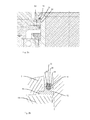
- FIGS. 2a and 2b show a device according to the invention in a first embodiment.
- a sealing device 10 is provided, which as in Fig. 2a shown, each having a base body 12 and a biasing body 14. More precisely, two such sealing devices 10 are provided here, which delimit a channel.
- the reference numeral 62 denotes a leakage space in which medium from the opposite side relative to the sealing device 10 in the event of a defect of a sealing device 10 can collect. This occasionally existing medium can be discharged via a (not shown) leakage channel in the outer wall 2a, for example, down and there are recognized, for example, via a sensor, also not shown.
- the reference numeral 64 denotes a preferably positive rotation. This rotation lock can engage in a protrusion 16 forming a clamping lip of the base body 12 and transmits the rotation of the media guiding device 4 to the sealing device 10.
- a region forming a flange 68 which here is a component of the media guiding device 4, causes the sealing device 10 to become trapped. This also transfers the rotation of the media guiding device 4 to the sealing device 10 in addition to an axial and radial fixation of the sealing device 10.
- the reference numeral 2a again indicates the outer wall of the channel 2, which is designed as a fixed hollow shaft.
- Fig. 2b shows a detailed view of the seal assembly Fig. 2a , It can be seen that here the main body 12 has two sections 22 and 24, wherein the section 24 is a primary sealing lip and the section 22 is a static sealing lip.
- the biasing element designated in its entirety by 14 has a projection 28 which terminates flush with the two elements 22 and 24 here.
- the pretensioning element is designed as a body with a substantially circular cross-section and additionally the projection 28. The movement takes place here between the primary sealing lip 24 and the outer wall 2a.
- the projection 16 extends in a region of the media guide 4 and is supported by the regions 68 (from below) and 8 (from above). In the area 68, as shown above, a leakage chamber 62 may be incorporated.
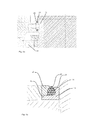
- FIGS. 3a and 3b show a further embodiment of a seal according to the invention.
- the arrangement of the device itself is as in Fig. 2a , so that it can be referenced.
- FIG. 3b shows the sealing device in an enlarged view.
- a base body 12 is provided, which has the two side members 22 and 24.
- the projection 28 again terminates substantially flush with the two elements 22 and 24.
- a connecting bore or a channel 36 is provided, which connects a recess 34, which is formed in the base body 12 below the biasing member 14, to the leakage space 62.
- the biasing member 14 on a game down towards, so that the biasing member 14 can also expand. More specifically, the main body 12 is cut free in the region 34. In this way, a game between the biasing member 14 and the base body 12 is provided.
- cleaning mediums can also be supplied to the biasing element 14.
- FIG. 3b opens the connecting hole 36 very close to the biasing member 14 in the recess 34 a.
- the connecting hole 36 opens at the lowest point of the recess 34 in the recess 34. Thus, no media can accumulate in this area and the recess 34 runs empty.
- the reference numeral 32 also here again identifies the front-flush contour.
- FIGS. 4a and 4b show a further embodiment of a device according to the invention, wherein here again essentially on Fig. 4b Reference is made.
- a base body 12 is provided, the biasing element 14 is here but not only on the base body 12, but also on a component 20 of the media guiding device.
- the biasing member 14 also causes a static seal, ie a seal against the rotating component.
- the component 20 of the media guiding device may be integrally connected to the media guiding device 4, as in FIG FIG. 4a represented or used as an additional component as in FIG. 4b shown.
- the main body here again has a radially protruding projection 16, i. a clamping lip, which serves to clamp the body.
- the sealing device according to the invention is not limited to the arrangement shown in the embodiments for a media feed from below.
- the fixed terminals 52, 55 are also supplied in the direction of the axis of rotation from above.
- the media distribution device is suitable for use in other container treatment machines, such as Rotationsrinsern or sterilizers.
- the respectively used for use media such as water, sterile water, sterile air, inert gases, disinfectant solutions, gaseous disinfectant, filling product and the like and as described above CIP media over a or a plurality of annular channels 56 distributed to the individual container treatment stations, such as Rinsdüsen. Since these machines usually no product tank on the carousel is necessary, this can be used instead of a fixed hollow shaft, which forms the main channel 2, a shaft made of solid material in the production according to the number of used media channels 54 drilled be, which are then connected according to ring channels 56. All disclosed in the application documents features are claimed as essential to the invention, provided they are new individually or in combination over the prior art.
Landscapes
- Engineering & Computer Science (AREA)
- General Engineering & Computer Science (AREA)
- Mechanical Engineering (AREA)
- Filling Of Jars Or Cans And Processes For Cleaning And Sealing Jars (AREA)
- Devices For Dispensing Beverages (AREA)
Priority Applications (1)
| Application Number | Priority Date | Filing Date | Title |
|---|---|---|---|
| SI201130719T SI2357151T1 (sl) | 2010-02-17 | 2011-02-15 | Naprava za porazdelitev medija za polnilna postrojenja |
Applications Claiming Priority (1)
| Application Number | Priority Date | Filing Date | Title |
|---|---|---|---|
| DE102010008366A DE102010008366A1 (de) | 2010-02-17 | 2010-02-17 | Medienverteilvorrichtung für Abfüllanlagen |
Publications (3)
| Publication Number | Publication Date |
|---|---|
| EP2357151A2 true EP2357151A2 (fr) | 2011-08-17 |
| EP2357151A3 EP2357151A3 (fr) | 2013-06-26 |
| EP2357151B1 EP2357151B1 (fr) | 2015-10-28 |
Family
ID=43903849
Family Applications (1)
| Application Number | Title | Priority Date | Filing Date |
|---|---|---|---|
| EP11154449.0A Active EP2357151B1 (fr) | 2010-02-17 | 2011-02-15 | Dispositif de répartition de fluide pour installations de remplissage |
Country Status (4)
| Country | Link |
|---|---|
| EP (1) | EP2357151B1 (fr) |
| CN (1) | CN102168777B (fr) |
| DE (1) | DE102010008366A1 (fr) |
| SI (1) | SI2357151T1 (fr) |
Cited By (2)
| Publication number | Priority date | Publication date | Assignee | Title |
|---|---|---|---|---|
| EP3040306A1 (fr) * | 2014-12-29 | 2016-07-06 | Sidel Participations, S.A.S. | Collecteur destiné à un réservoir rotatif d'une unité de remplissage pour remplir une pluralité d'articles avec un produit pouvant être versé |
| EP3620428A1 (fr) * | 2018-09-07 | 2020-03-11 | KRONES Aktiengesellschaft | Distributeur de milieux pour une machine rotative et machine de remplissage |
Families Citing this family (4)
| Publication number | Priority date | Publication date | Assignee | Title |
|---|---|---|---|---|
| DE102014109082A1 (de) | 2014-06-27 | 2015-12-31 | Krones Aktiengesellschaft | Drehverteiler zum Verteilen von fließfähigen Medien |
| CN104265905A (zh) * | 2014-10-06 | 2015-01-07 | 苏州蓝王机床工具科技有限公司 | 一种减摩式密封圈 |
| CN114992325A (zh) * | 2022-06-02 | 2022-09-02 | 杭州熵竭科技有限公司 | 密封结构及二氧化碳密封系统 |
| WO2026068850A1 (fr) * | 2024-09-30 | 2026-04-02 | Sidel Participations | Joint rotatif pour une machine de remplissage rotative |
Citations (1)
| Publication number | Priority date | Publication date | Assignee | Title |
|---|---|---|---|---|
| DE102006038747A1 (de) | 2006-08-17 | 2008-03-20 | Khs Ag | Dichtanordnung für eine Drehlagervorrichtung |
Family Cites Families (9)
| Publication number | Priority date | Publication date | Assignee | Title |
|---|---|---|---|---|
| AT304971B (de) * | 1968-08-02 | 1973-02-12 | Jenoe Szepesvary Dipl Ing | Dichtung, die als Radial- oder Axialdichtung ausgebildet ist |
| DE29620323U1 (de) * | 1996-11-22 | 1997-01-23 | Krones Ag Hermann Kronseder Maschinenfabrik, 93073 Neutraubling | Drehverteiler für rotierende Gefäßfüllmaschinen |
| US6450502B1 (en) * | 1998-11-14 | 2002-09-17 | Ti Specialty Polymer Products, Inc. | Rotary seal with relief angle for controlled tipping |
| DE20018509U1 (de) * | 2000-10-28 | 2001-01-11 | Bode GmbH, 22549 Hamburg | Dichtring für rotierende und/oder axialbewegliche Elemente aus Kunststoff |
| US6918595B2 (en) * | 2002-11-22 | 2005-07-19 | Dionex Corporation | Seal for high-pressure pumping system |
| AT7274U1 (de) * | 2003-11-05 | 2004-12-27 | Economos Austria Ges M B H | Ringdichtung |
| JP4426334B2 (ja) * | 2004-02-25 | 2010-03-03 | 三菱電線工業株式会社 | シール材 |
| US7140291B2 (en) * | 2005-01-28 | 2006-11-28 | Bendix Commercial Vehicle Systems Llc | Oil-free/oil-less air compressor with an improved seal |
| DE102006023157B3 (de) * | 2006-05-16 | 2008-01-24 | Trelleborg Sealing Solutions Germany Gmbh | Dichtungsanordnung zur Druckentlastung |
-
2010
- 2010-02-17 DE DE102010008366A patent/DE102010008366A1/de not_active Withdrawn
-
2011
- 2011-02-14 CN CN201110037792.6A patent/CN102168777B/zh active Active
- 2011-02-15 EP EP11154449.0A patent/EP2357151B1/fr active Active
- 2011-02-15 SI SI201130719T patent/SI2357151T1/sl unknown
Patent Citations (1)
| Publication number | Priority date | Publication date | Assignee | Title |
|---|---|---|---|---|
| DE102006038747A1 (de) | 2006-08-17 | 2008-03-20 | Khs Ag | Dichtanordnung für eine Drehlagervorrichtung |
Cited By (3)
| Publication number | Priority date | Publication date | Assignee | Title |
|---|---|---|---|---|
| EP3040306A1 (fr) * | 2014-12-29 | 2016-07-06 | Sidel Participations, S.A.S. | Collecteur destiné à un réservoir rotatif d'une unité de remplissage pour remplir une pluralité d'articles avec un produit pouvant être versé |
| EP3620428A1 (fr) * | 2018-09-07 | 2020-03-11 | KRONES Aktiengesellschaft | Distributeur de milieux pour une machine rotative et machine de remplissage |
| US11358849B2 (en) | 2018-09-07 | 2022-06-14 | Krones Ag | Media distributor for a rotary machine and filling machine |
Also Published As
| Publication number | Publication date |
|---|---|
| EP2357151B1 (fr) | 2015-10-28 |
| CN102168777A (zh) | 2011-08-31 |
| SI2357151T1 (sl) | 2016-02-29 |
| DE102010008366A1 (de) | 2011-08-18 |
| CN102168777B (zh) | 2014-07-23 |
| EP2357151A3 (fr) | 2013-06-26 |
Similar Documents
| Publication | Publication Date | Title |
|---|---|---|
| EP2357151B1 (fr) | Dispositif de répartition de fluide pour installations de remplissage | |
| EP2960201B1 (fr) | Distributeur rotatif destiné à distribuer des milieux pouvant s'écouler | |
| EP2030941B1 (fr) | Dispositif de répartition de milieux | |
| EP2879961B1 (fr) | Élément de remplissage et appareil de remplissage | |
| DE102009009339A1 (de) | Füllelement zum Füllen von Flaschen oder dergleichen Behältern sowie Füllmaschine mit derartigen Füllelementen | |
| EP2850351A1 (fr) | Soupape et diaphragme de soupape | |
| EP2397727A1 (fr) | Tête de soupape en plusieurs parties | |
| WO2014023366A1 (fr) | Élément de remplissage multiple destiné à un système de remplissage ou à une machine de remplissage, et machine de remplissage | |
| WO2014139627A1 (fr) | Distributeur rotatif de milieux pour machines de remplissage de contenants | |
| WO2012163556A1 (fr) | Passage tournant à manchon d'étanchéité | |
| DE102015118671A1 (de) | Vorrichtung zum Befüllen von Behältern mit einem Füllprodukt | |
| EP2831419B1 (fr) | Système d'étanchéité | |
| EP2900590B1 (fr) | Machine de remplissage | |
| WO2010009817A1 (fr) | Passage et machine de traitement de récipients comprenant des passages de ce type | |
| DE102006046479A1 (de) | Behälter mit einem Dichtelement | |
| EP2094600A2 (fr) | Remplisseuse | |
| EP4562309A1 (fr) | Pompe centrifuge avec joint d'étanchéité rotatif pour l'étanchéification de l'espace de roue et procédé de fabrication d'une roue de pompe | |
| EP0616971A1 (fr) | Machine de remplissage | |
| DE102007062470A1 (de) | Vorrichtung zum Verteilen von Medien | |
| EP2949930B1 (fr) | Piston pour une pompe de dosage | |
| EP3438514B1 (fr) | Soupape à double siège pour conduites de produit aseptiques | |
| DE102011111706B4 (de) | Zellenradschleuse | |
| DE10331946B4 (de) | Vorrichtung zur Behandlung von Werkstücken | |
| DE102008017768A1 (de) | Sperreinrichtung zwischen einem unsterilen Bereich und einem sterilen Bereich | |
| DE102017107844B4 (de) | Drei-Wege-Kugelhahn, Verfahren zum Herstellen sowie zum Zusammenbau eines derartigen Kugelhahns |
Legal Events
| Date | Code | Title | Description |
|---|---|---|---|
| PUAI | Public reference made under article 153(3) epc to a published international application that has entered the european phase |
Free format text: ORIGINAL CODE: 0009012 |
|
| AK | Designated contracting states |
Kind code of ref document: A2 Designated state(s): AL AT BE BG CH CY CZ DE DK EE ES FI FR GB GR HR HU IE IS IT LI LT LU LV MC MK MT NL NO PL PT RO RS SE SI SK SM TR |
|
| AX | Request for extension of the european patent |
Extension state: BA ME |
|
| PUAL | Search report despatched |
Free format text: ORIGINAL CODE: 0009013 |
|
| AK | Designated contracting states |
Kind code of ref document: A3 Designated state(s): AL AT BE BG CH CY CZ DE DK EE ES FI FR GB GR HR HU IE IS IT LI LT LU LV MC MK MT NL NO PL PT RO RS SE SI SK SM TR |
|
| AX | Request for extension of the european patent |
Extension state: BA ME |
|
| RIC1 | Information provided on ipc code assigned before grant |
Ipc: B67C 3/22 20060101AFI20130522BHEP Ipc: F16J 15/32 20060101ALI20130522BHEP |
|
| 17P | Request for examination filed |
Effective date: 20131218 |
|
| RBV | Designated contracting states (corrected) |
Designated state(s): AL AT BE BG CH CY CZ DE DK EE ES FI FR GB GR HR HU IE IS IT LI LT LU LV MC MK MT NL NO PL PT RO RS SE SI SK SM TR |
|
| 17Q | First examination report despatched |
Effective date: 20140730 |
|
| GRAP | Despatch of communication of intention to grant a patent |
Free format text: ORIGINAL CODE: EPIDOSNIGR1 |
|
| INTG | Intention to grant announced |
Effective date: 20150529 |
|
| GRAS | Grant fee paid |
Free format text: ORIGINAL CODE: EPIDOSNIGR3 |
|
| GRAA | (expected) grant |
Free format text: ORIGINAL CODE: 0009210 |
|
| AK | Designated contracting states |
Kind code of ref document: B1 Designated state(s): AL AT BE BG CH CY CZ DE DK EE ES FI FR GB GR HR HU IE IS IT LI LT LU LV MC MK MT NL NO PL PT RO RS SE SI SK SM TR |
|
| REG | Reference to a national code |
Ref country code: GB Ref legal event code: FG4D Free format text: NOT ENGLISH |
|
| REG | Reference to a national code |
Ref country code: CH Ref legal event code: EP |
|
| REG | Reference to a national code |
Ref country code: AT Ref legal event code: REF Ref document number: 757822 Country of ref document: AT Kind code of ref document: T Effective date: 20151115 |
|
| REG | Reference to a national code |
Ref country code: IE Ref legal event code: FG4D Free format text: LANGUAGE OF EP DOCUMENT: GERMAN |
|
| REG | Reference to a national code |
Ref country code: DE Ref legal event code: R096 Ref document number: 502011008201 Country of ref document: DE |
|
| REG | Reference to a national code |
Ref country code: FR Ref legal event code: PLFP Year of fee payment: 6 |
|
| REG | Reference to a national code |
Ref country code: LT Ref legal event code: MG4D |
|
| REG | Reference to a national code |
Ref country code: NL Ref legal event code: MP Effective date: 20151028 |
|
| PG25 | Lapsed in a contracting state [announced via postgrant information from national office to epo] |
Ref country code: NO Free format text: LAPSE BECAUSE OF FAILURE TO SUBMIT A TRANSLATION OF THE DESCRIPTION OR TO PAY THE FEE WITHIN THE PRESCRIBED TIME-LIMIT Effective date: 20160128 Ref country code: LT Free format text: LAPSE BECAUSE OF FAILURE TO SUBMIT A TRANSLATION OF THE DESCRIPTION OR TO PAY THE FEE WITHIN THE PRESCRIBED TIME-LIMIT Effective date: 20151028 Ref country code: NL Free format text: LAPSE BECAUSE OF FAILURE TO SUBMIT A TRANSLATION OF THE DESCRIPTION OR TO PAY THE FEE WITHIN THE PRESCRIBED TIME-LIMIT Effective date: 20151028 Ref country code: HR Free format text: LAPSE BECAUSE OF FAILURE TO SUBMIT A TRANSLATION OF THE DESCRIPTION OR TO PAY THE FEE WITHIN THE PRESCRIBED TIME-LIMIT Effective date: 20151028 Ref country code: IS Free format text: LAPSE BECAUSE OF FAILURE TO SUBMIT A TRANSLATION OF THE DESCRIPTION OR TO PAY THE FEE WITHIN THE PRESCRIBED TIME-LIMIT Effective date: 20160228 Ref country code: ES Free format text: LAPSE BECAUSE OF FAILURE TO SUBMIT A TRANSLATION OF THE DESCRIPTION OR TO PAY THE FEE WITHIN THE PRESCRIBED TIME-LIMIT Effective date: 20151028 |
|
| PG25 | Lapsed in a contracting state [announced via postgrant information from national office to epo] |
Ref country code: BE Free format text: LAPSE BECAUSE OF NON-PAYMENT OF DUE FEES Effective date: 20160229 Ref country code: PL Free format text: LAPSE BECAUSE OF FAILURE TO SUBMIT A TRANSLATION OF THE DESCRIPTION OR TO PAY THE FEE WITHIN THE PRESCRIBED TIME-LIMIT Effective date: 20151028 Ref country code: FI Free format text: LAPSE BECAUSE OF FAILURE TO SUBMIT A TRANSLATION OF THE DESCRIPTION OR TO PAY THE FEE WITHIN THE PRESCRIBED TIME-LIMIT Effective date: 20151028 Ref country code: GR Free format text: LAPSE BECAUSE OF FAILURE TO SUBMIT A TRANSLATION OF THE DESCRIPTION OR TO PAY THE FEE WITHIN THE PRESCRIBED TIME-LIMIT Effective date: 20160129 Ref country code: PT Free format text: LAPSE BECAUSE OF FAILURE TO SUBMIT A TRANSLATION OF THE DESCRIPTION OR TO PAY THE FEE WITHIN THE PRESCRIBED TIME-LIMIT Effective date: 20160229 Ref country code: LV Free format text: LAPSE BECAUSE OF FAILURE TO SUBMIT A TRANSLATION OF THE DESCRIPTION OR TO PAY THE FEE WITHIN THE PRESCRIBED TIME-LIMIT Effective date: 20151028 Ref country code: SE Free format text: LAPSE BECAUSE OF FAILURE TO SUBMIT A TRANSLATION OF THE DESCRIPTION OR TO PAY THE FEE WITHIN THE PRESCRIBED TIME-LIMIT Effective date: 20151028 Ref country code: RS Free format text: LAPSE BECAUSE OF FAILURE TO SUBMIT A TRANSLATION OF THE DESCRIPTION OR TO PAY THE FEE WITHIN THE PRESCRIBED TIME-LIMIT Effective date: 20151028 |
|
| PG25 | Lapsed in a contracting state [announced via postgrant information from national office to epo] |
Ref country code: CZ Free format text: LAPSE BECAUSE OF FAILURE TO SUBMIT A TRANSLATION OF THE DESCRIPTION OR TO PAY THE FEE WITHIN THE PRESCRIBED TIME-LIMIT Effective date: 20151028 |
|
| REG | Reference to a national code |
Ref country code: DE Ref legal event code: R097 Ref document number: 502011008201 Country of ref document: DE |
|
| PG25 | Lapsed in a contracting state [announced via postgrant information from national office to epo] |
Ref country code: SK Free format text: LAPSE BECAUSE OF FAILURE TO SUBMIT A TRANSLATION OF THE DESCRIPTION OR TO PAY THE FEE WITHIN THE PRESCRIBED TIME-LIMIT Effective date: 20151028 Ref country code: RO Free format text: LAPSE BECAUSE OF FAILURE TO SUBMIT A TRANSLATION OF THE DESCRIPTION OR TO PAY THE FEE WITHIN THE PRESCRIBED TIME-LIMIT Effective date: 20151028 Ref country code: DK Free format text: LAPSE BECAUSE OF FAILURE TO SUBMIT A TRANSLATION OF THE DESCRIPTION OR TO PAY THE FEE WITHIN THE PRESCRIBED TIME-LIMIT Effective date: 20151028 Ref country code: SM Free format text: LAPSE BECAUSE OF FAILURE TO SUBMIT A TRANSLATION OF THE DESCRIPTION OR TO PAY THE FEE WITHIN THE PRESCRIBED TIME-LIMIT Effective date: 20151028 Ref country code: EE Free format text: LAPSE BECAUSE OF FAILURE TO SUBMIT A TRANSLATION OF THE DESCRIPTION OR TO PAY THE FEE WITHIN THE PRESCRIBED TIME-LIMIT Effective date: 20151028 |
|
| PLBE | No opposition filed within time limit |
Free format text: ORIGINAL CODE: 0009261 |
|
| STAA | Information on the status of an ep patent application or granted ep patent |
Free format text: STATUS: NO OPPOSITION FILED WITHIN TIME LIMIT |
|
| PG25 | Lapsed in a contracting state [announced via postgrant information from national office to epo] |
Ref country code: MC Free format text: LAPSE BECAUSE OF FAILURE TO SUBMIT A TRANSLATION OF THE DESCRIPTION OR TO PAY THE FEE WITHIN THE PRESCRIBED TIME-LIMIT Effective date: 20151028 Ref country code: LU Free format text: LAPSE BECAUSE OF FAILURE TO SUBMIT A TRANSLATION OF THE DESCRIPTION OR TO PAY THE FEE WITHIN THE PRESCRIBED TIME-LIMIT Effective date: 20160215 |
|
| REG | Reference to a national code |
Ref country code: CH Ref legal event code: PL |
|
| 26N | No opposition filed |
Effective date: 20160729 |
|
| GBPC | Gb: european patent ceased through non-payment of renewal fee |
Effective date: 20160215 |
|
| PG25 | Lapsed in a contracting state [announced via postgrant information from national office to epo] |
Ref country code: LI Free format text: LAPSE BECAUSE OF NON-PAYMENT OF DUE FEES Effective date: 20160229 Ref country code: CH Free format text: LAPSE BECAUSE OF NON-PAYMENT OF DUE FEES Effective date: 20160229 |
|
| REG | Reference to a national code |
Ref country code: IE Ref legal event code: MM4A |
|
| REG | Reference to a national code |
Ref country code: FR Ref legal event code: PLFP Year of fee payment: 7 |
|
| PG25 | Lapsed in a contracting state [announced via postgrant information from national office to epo] |
Ref country code: IE Free format text: LAPSE BECAUSE OF NON-PAYMENT OF DUE FEES Effective date: 20160215 Ref country code: GB Free format text: LAPSE BECAUSE OF NON-PAYMENT OF DUE FEES Effective date: 20160215 |
|
| REG | Reference to a national code |
Ref country code: AT Ref legal event code: MM01 Ref document number: 757822 Country of ref document: AT Kind code of ref document: T Effective date: 20160215 |
|
| PG25 | Lapsed in a contracting state [announced via postgrant information from national office to epo] |
Ref country code: AT Free format text: LAPSE BECAUSE OF NON-PAYMENT OF DUE FEES Effective date: 20160215 |
|
| PG25 | Lapsed in a contracting state [announced via postgrant information from national office to epo] |
Ref country code: MT Free format text: LAPSE BECAUSE OF FAILURE TO SUBMIT A TRANSLATION OF THE DESCRIPTION OR TO PAY THE FEE WITHIN THE PRESCRIBED TIME-LIMIT Effective date: 20151028 |
|
| REG | Reference to a national code |
Ref country code: FR Ref legal event code: PLFP Year of fee payment: 8 |
|
| PG25 | Lapsed in a contracting state [announced via postgrant information from national office to epo] |
Ref country code: HU Free format text: LAPSE BECAUSE OF FAILURE TO SUBMIT A TRANSLATION OF THE DESCRIPTION OR TO PAY THE FEE WITHIN THE PRESCRIBED TIME-LIMIT; INVALID AB INITIO Effective date: 20110215 Ref country code: CY Free format text: LAPSE BECAUSE OF FAILURE TO SUBMIT A TRANSLATION OF THE DESCRIPTION OR TO PAY THE FEE WITHIN THE PRESCRIBED TIME-LIMIT Effective date: 20151028 |
|
| PG25 | Lapsed in a contracting state [announced via postgrant information from national office to epo] |
Ref country code: MK Free format text: LAPSE BECAUSE OF FAILURE TO SUBMIT A TRANSLATION OF THE DESCRIPTION OR TO PAY THE FEE WITHIN THE PRESCRIBED TIME-LIMIT Effective date: 20151028 Ref country code: TR Free format text: LAPSE BECAUSE OF FAILURE TO SUBMIT A TRANSLATION OF THE DESCRIPTION OR TO PAY THE FEE WITHIN THE PRESCRIBED TIME-LIMIT Effective date: 20151028 |
|
| PG25 | Lapsed in a contracting state [announced via postgrant information from national office to epo] |
Ref country code: BG Free format text: LAPSE BECAUSE OF FAILURE TO SUBMIT A TRANSLATION OF THE DESCRIPTION OR TO PAY THE FEE WITHIN THE PRESCRIBED TIME-LIMIT Effective date: 20151028 |
|
| PG25 | Lapsed in a contracting state [announced via postgrant information from national office to epo] |
Ref country code: AL Free format text: LAPSE BECAUSE OF FAILURE TO SUBMIT A TRANSLATION OF THE DESCRIPTION OR TO PAY THE FEE WITHIN THE PRESCRIBED TIME-LIMIT Effective date: 20151028 |
|
| P01 | Opt-out of the competence of the unified patent court (upc) registered |
Effective date: 20230523 |
|
| PGFP | Annual fee paid to national office [announced via postgrant information from national office to epo] |
Ref country code: FR Payment date: 20251231 Year of fee payment: 16 |
|
| PGFP | Annual fee paid to national office [announced via postgrant information from national office to epo] |
Ref country code: DE Payment date: 20251230 Year of fee payment: 16 |
|
| PGFP | Annual fee paid to national office [announced via postgrant information from national office to epo] |
Ref country code: IT Payment date: 20260122 Year of fee payment: 16 |
|
| PGFP | Annual fee paid to national office [announced via postgrant information from national office to epo] |
Ref country code: SI Payment date: 20260114 Year of fee payment: 16 |