EP2357329A2 - U-Typ-Plattenwärmeaustauscher mit Mischkammer - Google Patents
U-Typ-Plattenwärmeaustauscher mit Mischkammer Download PDFInfo
- Publication number
- EP2357329A2 EP2357329A2 EP11000382A EP11000382A EP2357329A2 EP 2357329 A2 EP2357329 A2 EP 2357329A2 EP 11000382 A EP11000382 A EP 11000382A EP 11000382 A EP11000382 A EP 11000382A EP 2357329 A2 EP2357329 A2 EP 2357329A2
- Authority
- EP
- European Patent Office
- Prior art keywords
- hot fluid
- passage
- hot
- heat exchanger
- header
- Prior art date
- Legal status (The legal status is an assumption and is not a legal conclusion. Google has not performed a legal analysis and makes no representation as to the accuracy of the status listed.)
- Withdrawn
Links
Images


Classifications
-
- F—MECHANICAL ENGINEERING; LIGHTING; HEATING; WEAPONS; BLASTING
- F28—HEAT EXCHANGE IN GENERAL
- F28D—HEAT-EXCHANGE APPARATUS, NOT PROVIDED FOR IN ANOTHER SUBCLASS, IN WHICH THE HEAT-EXCHANGE MEDIA DO NOT COME INTO DIRECT CONTACT
- F28D9/00—Heat-exchange apparatus having stationary plate-like or laminated conduit assemblies for both heat-exchange media, the media being in contact with different sides of a conduit wall
- F28D9/0062—Heat-exchange apparatus having stationary plate-like or laminated conduit assemblies for both heat-exchange media, the media being in contact with different sides of a conduit wall the conduits for one heat-exchange medium being formed by spaced plates with inserted elements
- F28D9/0068—Heat-exchange apparatus having stationary plate-like or laminated conduit assemblies for both heat-exchange media, the media being in contact with different sides of a conduit wall the conduits for one heat-exchange medium being formed by spaced plates with inserted elements with means for changing flow direction of one heat exchange medium, e.g. using deflecting zones
-
- F—MECHANICAL ENGINEERING; LIGHTING; HEATING; WEAPONS; BLASTING
- F28—HEAT EXCHANGE IN GENERAL
- F28F—DETAILS OF HEAT-EXCHANGE AND HEAT-TRANSFER APPARATUS, OF GENERAL APPLICATION
- F28F9/00—Casings; Header boxes; Auxiliary supports for elements; Auxiliary members within casings
- F28F9/02—Header boxes; End plates
-
- F—MECHANICAL ENGINEERING; LIGHTING; HEATING; WEAPONS; BLASTING
- F01—MACHINES OR ENGINES IN GENERAL; ENGINE PLANTS IN GENERAL; STEAM ENGINES
- F01M—LUBRICATING OF MACHINES OR ENGINES IN GENERAL; LUBRICATING INTERNAL COMBUSTION ENGINES; CRANKCASE VENTILATING
- F01M5/00—Heating, cooling, or controlling temperature of lubricant; Lubrication means facilitating engine starting
- F01M5/002—Cooling
-
- F—MECHANICAL ENGINEERING; LIGHTING; HEATING; WEAPONS; BLASTING
- F28—HEAT EXCHANGE IN GENERAL
- F28D—HEAT-EXCHANGE APPARATUS, NOT PROVIDED FOR IN ANOTHER SUBCLASS, IN WHICH THE HEAT-EXCHANGE MEDIA DO NOT COME INTO DIRECT CONTACT
- F28D21/00—Heat-exchange apparatus not covered by any of the groups F28D1/00 - F28D20/00
- F28D2021/0019—Other heat exchangers for particular applications; Heat exchange systems not otherwise provided for
- F28D2021/008—Other heat exchangers for particular applications; Heat exchange systems not otherwise provided for for vehicles
- F28D2021/0089—Oil coolers
Definitions
- the present invention relates to a heat exchanger suitable for an aircraft engine oil cooler. More specifically, the present invention relates to a stack type heat exchanger in which U-turn type layered hot fluid passages through which a hot fluid circulates and U-turn type layered cold fluid passages through which a cold fluid circulates are alternately stacked.
- the plate-fin type heat exchanger is a kind of a stack type heat exchanger including, as a main configuration member, a stacked core 10 in which layered hot fluid passages 11 having plate-like fins called corrugated fins and layered cold fluid passages 12 having plate-like fins called corrugated fins are alternately stacked, and partition plates 13 called tube plates are provided between the hot fluid passages 11 and the cold fluid passages 12.
- partition plates 13 called tube plates are provided between the hot fluid passages 11 and the cold fluid passages 12.
- tube plates are joined as end plates 14 on both sides in the stacking direction of the stacked core 10.
- Each of the hot fluid passages 11 and each of the cold fluid passages 12 of the stacked core 10 are both of a U-turn type in which a fluid makes a U-turn and circulates in a plane perpendicular to the layer thickness direction, and a partitioning member 15 is provided in the center portion in the width direction perpendicular to the fluid circulation direction to form its first half and its return path.
- an inlet port 12a and an outlet port 12b of the cold fluid passage 12 are opened to one end face of the stacked core 10, and an inlet port 11a and an outlet port 11b of the hot fluid passage 11 are opened to the ends on the entrance and outlet ports side of the cold fluid passage 12 on both side surfaces of the stacked core 10.
- an engine oil circulates in the hot fluid passage 11, and at the same time, a fuel circulates in the cold fluid passage 12, so that heat exchange is performed between the cold fuel and the hot engine oil to cool the hot engine oil.
- the oil cooler can serve as a fuel preheater.
- the temperature of the engine oil before heat exchange is typically approximately -50 to 200°C, and likewise, the fuel temperature before heat exchange is typically approximately -75 to 150°C depending on a flight altitude or the like.
- the circulation directions of the engine oil and the fuel herein are the same.
- the plate-fin type heat exchanger described in Japanese Patent Application Laid-Open No. 2000-097582 is of a stacked parallel flow type.
- the circulation directions of the fuel and the engine oil can be counter, which in this case, is called a stacked counterflow type.
- the temperature of the engine oil circulating in the layered hot fluid passage 11 is gradually decreased from the inlet port 11a to the outlet port 11b so that the temperature distribution in the passage width direction perpendicular to the fluid circulation direction and perpendicular to the layer thickness direction is uniform, but actually, the tendency of the temperature to be decreased is stronger toward the inside of the U-turn passage, that is, toward the vicinity of the partitioning member 15 which partitions the first half and the return path.
- the plate-fin type heat exchanger described in Japanese Patent Application Laid-Open No. 2000-097582 degrades the thermal conductivity of the partitioning member 15 which partitions the first half and the return path of the U-turn type hot fluid passage.
- the grounds are as follows.
- the relatively hot oil circulating in the first half of the hot fluid passage 11 is cooled by the relatively cold oil circulating in the return path across the partitioning member 15, which causes the temperature in the vicinity of the partitioning member 15 to be decreased.
- the configuring material of the partitioning member 15 is replaced with a material with low thermal conductivity , such as ceramics, to inhibit heat conduction from the first half to the return path across the partitioning member 15, so that the temperature distribution in the passage width direction perpendicular to the fluid circulation direction is made uniform.
- the effect of this means is limitative, and in an aircraft such as a large jet plane which flies at a high altitude, the temperature distribution in the passage width direction perpendicular to the fluid circulation direction in the first half and the return path of the hot fluid passage 11 is still non-uniform, so that the heat conduction ability is found to be degraded due to the reduction of the heat transmission surface.
- the aircraft engine oil cooler is often equipped with a bypass mechanism to rapidly increase the temperature of the engine oil at engine start.
- the bypass mechanism is described in Japanese Utility Model Application Laid-Open No. 01-067479 or the like.
- the configuration of the plate-fin type heat exchanger for the oil cooler equipped with the bypass mechanism will be described with reference to Fig. 9 .
- the bypass mechanism has an entrance/outlet port 11c provided to the side surface on the first half side of the hot fluid passage 11 of the stacked core 10, a bypass header 20 which communicates with the entrance/outlet port 11c in the stacking direction, a bypass pipe 21 which directly connects the bypass header 20 to the outlet port 11b of the hot fluid passage 11, and an opening and closing mechanism of the bypass pipe 21.
- the bypass pipe 21 is typically brought into the closed state so that the oil circulating in the first half of the hot fluid passage 11 once flows out to the bypass header 20 and returns into the first half again.
- the bypass pipe 21 is brought into the opened state. Accordingly, the oil drawn into the first half of the hot fluid passage 11 is once drawn out from the middle of the first half to the outside of the stacked core 10 and passes around the stacked core 10 so as to be discharged to the outside of the heat exchanger.
- the cooling of the engine oil by the fuel can be avoided to enable the rapid temperature increase of the engine oil.
- the cold engine oil initially present in the heat exchanger is also gradually heated to decrease the viscosity.
- An object of the present invention is to provide a stack type heat exchanger which can eliminate the abnormal temperature distribution in the passage width direction of a hot fluid circulating in a U-turn type layered hot fluid passage, and can increase the heat transmission ability, in particular, can significantly increase the cold ability.
- the present applicant has manufactured the plate-fin type heat exchanger used as the aircraft engine oil cooler which is equipped with the bypass mechanism shown in Fig. 9 , more specifically, the counterflow type heat exchanger in which the circulation directions of the engine oil and the fuel are counter.
- the present inventors have initially considered that the abnormal temperature distribution in the width direction of the hot fluid circulating in the U-turn type layered hot fluid passage 11 is caused by the bypass mechanism, have experimentally manufactured the plate-fin type heat exchanger without the mechanism, and have examined in detail the effect of bypass mechanism on the non uniform oil temperature distribution. Consequently, contrary to expectations of the present inventors, by removing the bypass mechanism, the non-uniformity of the temperature distribution becomes more significant to degrade the heat exchanging performance.
- the bypass mechanism is used only at engine start, is brought into the off state at the time of the typical engine operation, and becomes a header bypass passage which only passes the oil circulating in the first half of the U-turn passage on the hot side through the bypass header 20.
- the oil circulating in the outside portion of the first half the portion far from the partitioning member 15 which partitions the first half and the return path of the U-turn passage
- the oil circulating in the inside portion of the first half the portion near the partitioning member 15
- the present inventors have considered that such oil mixing in the bypass header 20 causes the abnormal temperature distribution in the passage width direction of the hot fluid circulating in the hot fluid passage 11, but actually, has found to be an effective means for eliminating the abnormal temperature distribution.
- the bypass header 20 when the bypass header 20 is provided in the first half of the U-turn passage on the hot side, contrary to when there is not the bypass mechanism, on the return path side, the oil temperature in the outside portion (the portion far from the partitioning member 15) is lower than that of the inside portion (the portion near the partitioning member 15 which partitions the first half and the return path of the U-turn passage), so that the switching of the temperature distributions in the return path without the stacked core 10 completely functioning increases the heat exchanging performance, as compared with when there is not the bypass mechanism.
- the present inventors have provided the header bypass passages having the same function as the normal bypass mechanism in both the first half and the return path of the U-turn passage on the hot side.
- the abnormal temperature distribution in the hot fluid passage which has been the problem in the plate-fin type heat exchanger used as the aircraft engine oil cooler, the drift of the oil due to this, and the degradation of the heat exchanging performance can be effectively eliminated.
- the stack type heat exchanger of the present invention has been completed based on such findings, and includes a stacked core in which U-turn type layered hot fluid passages through which a hot fluid circulates and U-turn type layered cold fluid passages through which a cold fluid circulates are alternately stacked, wherein each of the outer surfaces of the stacked core on the first half side and on the return path side has a mixing header which communicates with each of the hot fluid passages in the stacking direction, wherein each of the hot fluid passages has therein a fluid draw-in/draw-out passage that passes the hot fluid circulating in each of the passages through the mixing header.
- the fluid draw-in/draw-out passage desirably passes the hot fluid circulating in the entire area in the width direction from the outside to the inside of the U-turn passage through the mixing header.
- the configuration in which the mixing header on the first half side serves as the bypass header is desirably reasonable.
- the counterflow type in which the circulation direction of the hot fluid in the hot fluid passage and the circulation direction of the cold fluid in the cold fluid passage are counter is preferable from the viewpoint of improving the heat exchanging performance.
- the hot fluid circulating in the hot fluid passages and the cold fluid circulating in the cold fluid passages exchange heat, so that the temperature of the hot fluid is decreased and thus the temperature of the cold fluid is increased.
- the hot fluid circulating in the U-turn passage on the hot side once flows out to the mixing header in the middle of the first half of the U-turn passage, and here, the fluid which flows through the inside portion of the U-turn passage and the fluid which flows through the outside portion thereof are mixed.
- the mixing of the hot fluids is performed in the stacking direction of the U-turn passage.
- the hot fluid circulating in the inside portion in each of the first half and the return path of the U-turn passage on the hot side is forcibly discharged to the outside of the stacked core and is actively stirred and mixed with the hot fluid circulating in the outside portion, which is the largest characteristic point in the stack type heat exchanger of the present invention.
- the heat exchanging performance of the stack type heat exchanger of the present invention is increased particularly when the hot fluid circulating in the entire area in the width direction from the outside to the inside of the U-turn passage passes through the mixing header to perform stirring and mixing.
- the heat exchanging performance of the counterflow type heat exchanger in which the circulation directions of the hot fluid and the fluid direction are counter is higher than that of the parallel flow type in which the circulation direction of the hot fluid and the fluid direction of the cold fluid are the same.
- the mixing header on the advance side is used as the bypass header so that the configuration is simplified.
- the mixing header is attached to the outer surface on the advance side and the outer surface on the return path side, and the hot fluid circulating in the first half or the return path is once discharged to the outside of the stacked core for stirring and mixing so as to be returned into the stacked core, so that the abnormal temperature distribution in the passage width direction of the hot fluid circulating in the U-turn passage on the hot side is reduced to enable the significant increase of the heat exchanging performance.
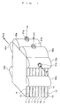
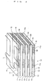
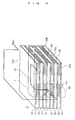
- a stack type heat exchanger of this embodiment is used as an aircraft engine oil cooler, and as shown in Figs. 1 and 2 , has a rectangular cuboid stacked core 10 including a plate-fin type heat exchanger of a counterflow type.
- layered hot fluid passages 11 including corrugated fins and layered cold fluid passage 12 including corrugated fins are alternately stacked.
- Partition plates 13 called tube plates are provided between the hot fluid passages 11 and the cold fluid passages 12, and both end faces in the stacking direction of the stacked core 10 are closed by end plates 14 called tube plates.
- each of the hot fluid passages 11 and each of the cold fluid passages 12 are both of a U-turn type, and a partitioning member 15 which partitions its first half and its return path is provided in the center portion in the width direction of each of the fluid passages except for the end on the passage reversing side (on the opposite side of the entrance and outlet ports side).
- An inlet port 12a and an outlet port 12b of the cold fluid passage 12 are opened side by side in the width direction on the end face on the entrance/exit side of the stacked core 10.
- An inlet port 11a of the hot fluid passage 11 is opened to the end on the entrance/exit side on one side surface of the stacked core 10, and an outlet port 11b of the hot fluid passage 11 is opened to the end on the entrance/exit side on the other side surface of the stacked core 10.
- a second entrance/outlet port 11c of the hot fluid passage 11a is provided to one side surface of the stacked core 10 so as to be located in the middle portion of the first half.
- a third entrance/outlet port 11d of the hot fluid passage 11a is provided to the other side surface of the stacked core 10 so as to be located in the middle portion of the return path.
- a vertical inlet header 30a which communicates with the inlet port 12a of the cold fluid passage 12 in the passage stacking direction and a vertical outlet header 30b which communicates with the outlet port 12b of the cold fluid passage 12 in the passage stacking direction are attached side by side in the width direction to the end face on the entrance/exit side of the stacked core 10.
- a vertical inlet header 40a which communicates with the inlet port 11a of the hot fluid passage 11 in the passage stacking direction is attached along the entire height
- a first vertical mixing header 50a which communicates with the second entrance/outlet port 11c of the hot fluid passage 11 in the passage stacking direction is attached along the entire height.
- a vertical outlet header 40b which communicates with the outlet port 11b of the hot fluid passage 11 in the passage stacking direction is attached in the stacking direction along the entire height
- a second vertical mixing header 50b which communicates with the third entrance/outlet port 11d of the hot fluid passage 11 in the passage stack direction is attached in the stacking direction along the entire height.
- All of the inlet header 30a and the outlet header 30b of the cold fluid, the inlet header 40a and the outlet header 40b of the hot fluid, and the first mixing header 50a and the second mixing header 50b are covers of a semicircular cross section along the entire length in the longitudinal direction (vertical direction), and both ends in the longitudinal direction of each of the headers are closed.
- an inlet 31a of the cold fluid is provided in the center portion in the longitudinal direction of the inlet header 30a
- an outlet 31b of the cold fluid is provided in the center portion in the longitudinal direction of the outlet header 30b
- an inlet 41a of the hot fluid is provided in the center portion in the longitudinal direction of the inlet header 40a
- an outlet 41b of the hot fluid is provided in the center portion in the longitudinal direction of the outlet header 40b.
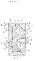
- the fluid circulation direction of a corrugated fin 16 arranged in the hot fluid passage 11 is along the direction of the first half and the return path of the U-turn passage on the hot side except for the following exceptions.
- a right triangular corrugated fin 16a in the different passage direction is arranged at the end of the entrance side of the U-turn passage on the hot side.
- a right triangular corrugated fin 16b in the different passage direction is arranged at the end on the exit side of the U-turn passage on the hot side.
- An isosceles triangular corrugated fin 16c in the different passage direction for reversing the passage is arranged at the end on the passage reversing side (on the opposite side of the entrance/exit side) of the U-turn passage on the hot side.
- an isosceles triangular corrugated fin 16d in the different passage direction is arranged as the fluid draw-in/draw-out passage for bypass so as to be located on the back side of the mixing header 50a.
- an isosceles triangular corrugated fin 16e in the different passage direction is arranged as the fluid draw-in/draw-out passage for bypass so as to be located on the back side of the mixing header 50b.
- the fluid circulation direction of a corrugated fin 17 arranged in the cold fluid passage 12 is along the direction of the first half and the return path of the U-turn passage on the cold side except that an isosceles triangular corrugated fin 17a in the different passage direction for reversing the passage is arranged at the end on the passage reversing side (on the opposite side of the entrance/exit side) of the U-turn passage on the cold side.
- the function of the stack type heat exchanger of this embodiment is as follows.
- the stack type heat exchanger of this embodiment is the plate-fin type heat exchanger of the counterflow type used as the aircraft engine oil cooler. For this reason, the hot fluid circulating in the hot fluid passage 11 is the hot engine oil to be cooled, and the cold fluid circulating in the cold fluid passage 12 is the cold fuel.
- the engine oil as the hot fluid flows from the inlet 11a through the inlet header 40a provided to one side surface on the entrance/exit side of the stacked core 10 into the first half of the hot fluid passage 11.
- the engine oil which advances in the first half passes in the fluid draw-in/draw-out passage 16d in the middle of the first half through the first mixing header 50a attached to the side surface of the stacked core 10 to return to the first half.
- the engine oil which has returned to the first half changes the direction on the other end side of the passage to enter the return path parallel with the first half.
- the engine oil which advances in the return path passes in the fluid draw-in/draw-out passage 16e in the middle of the return path through the second mixing header 50b attached to the side surface of the stacked core 10 to return into the return path.
- the engine oil is discharged from the outlet 11b provided to the other side surface on the entrance/exit side of the stacked core 10 through the outlet header 40b to the outside of the stacked core 10.
- the fuel as the cold fluid is drawn into and is drawn out from the end face on the entrance/exit side of the stacked core 10 to avoid the interference between the headers 40a and 40b on the hot side and between the headers 30a and 30b on the cold side.
- the U-turn type hot fluid passages 11 and the U-turn type cold fluid passages 12 are alternately stacked, so that the hot engine oil circulating in the hot fluid passages 11 and the fuel circulating in the cold fluid passages 12 in the reverse direction exchange heat to cool the engine oil.
- the mixing header 50a the engine oil circulating in the outside portion of the first half of the hot fluid passage 11 and the engine oil circulating in the inside portion of the first half are mixed.
- the engine oils are mixed between the stacked hot fluid passages 11. Accordingly, the non-uniform temperature distribution in the passage width direction of the hot fluid passage 11 and the non-uniform temperature distribution between the hot fluid passages 11 in the stacking direction can be eliminated.
- the temperature of the engine oil is decreased in the outside portion of the return path of the hot fluid passage 11, the temperature of the engine oil is increased in the inside portion, the flow in the outside portion becomes worsen, and the engine oil circulates only in the inside portion. For this reason, the designed heat exchange performance is not be achieved. Consequently, in the stack type heat exchanger of this embodiment, the total amount of the engine oil also passes through the mixing header 50b outside of the stacked core 10 in the return path of the hot fluid passage 11. Further, the engine oil circulating in the outside portion of the return path of the hot fluid passage 11 and the engine oil circulating in the inside portion in the return path are also mixed in the mixing header 50b. At the same time, the engine oils are mixed between the stacked hot fluid passages 11. From this, the non-uniform temperature distribution in the passage width direction of the hot fluid passage 11 and the non-uniform temperature distribution caused between the hot fluid passages 11 in the stacking direction can be eliminated.
- the temperature distribution in the passage width direction of the engine oil is made significantly uniform in both the first half and the return path of the U-turn passage on the hot side, and substantially the entire surface of the hot fluid passage 11 contributes to heat exchange, so that the heat exchanging performance is increased even at cold temperature, and the heat exchanger performance is achieved as designed.
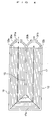
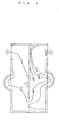
- Fig. 5 shows the analysis of the fluid temperature distribution in the hot fluid passage 11 in the stacked core 10.
- the temperature at the time of the inflow of the engine oil is 100°C.
- the temperature distribution in the passage width direction in the first half and the return path is found to be made uniform. In particular, the uniformity of the temperature distribution is significant on the downstream side of the mixing header 50b in the return path.
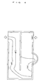
- Fig. 6 shows the temperature distribution of a conventional stack type heat exchanger ( Fig. 9 ) having only the bypass header 20. It is found that the uniformity of the temperature distribution in the width direction is significant on the return path side, the temperature in the outside portion of the passage is low, and only the inside portion substantially functions.
- the length of the stacked core 10 is approximately 400 mm, the width is approximately 200 mm, the height in the stacking direction is approximately 50 mm, the number of the hot fluid passages 11 is 7, the number of the cold fluid passages 12 is 6, and the layer thickness of each of the passages is approximately 3 mm.
- the aircraft fuel at approximately -50°C circulates in the cold fluid passage 12 at a flow rate of approximately 3 tons/h.
- the engine oil at approximately 100°C circulates in the hot fluid passage 11 at a flow rate of approximately 2 tons/h.
- the heat exchanging performance of the stack type heat exchanger of this embodiment provided with the mixing headers in the first half and the return path of the U-turn passage on the hot side is increased by 10% with respect to the conventional stack type heat exchanger provided with the bypass header on the first half side of the U-turn passage on the hot side.
- the heat exchanging performance of the stack type heat exchanger from which the bypass header is removed from the first half side of the U-turn passage on the hot side is decreased by 20% with respect to the conventional stack type heat exchanger provided with the bypass header on the first half side of the U-turn passage on the hot side.
- the mixing headers 50a and 50b are provided on the first half side and the return path side of the U-turn passage on the hot side, and as shown in Fig. 7 , the mixing header 50a on the first half side can be used as the bypass header.
- the outlet port 51a is provided in the center portion or the like on the back of the mixing header 50a, and is opened at the time of the use of the bypass function so as to be connected to the outlet port 41b of the outlet header 40b.
- the total amount of the hot fluid which has flowed from the inlet header 40a into the hot fluid passage 11 passes from the mixing header 50a to the outlet header 40b, so that the rapid temperature increase of the engine oil as the hot fluid is enabled, and the temperature increased engine oil passes through part of the inside of the heat exchanger, so that the temperature increase of the cold engine oil staying in the heat exchanger is enabled while the supply of the hot fluid is kept.
Landscapes
- Engineering & Computer Science (AREA)
- Physics & Mathematics (AREA)
- Thermal Sciences (AREA)
- Mechanical Engineering (AREA)
- General Engineering & Computer Science (AREA)
- Heat-Exchange Devices With Radiators And Conduit Assemblies (AREA)
Applications Claiming Priority (1)
| Application Number | Priority Date | Filing Date | Title |
|---|---|---|---|
| JP2010015059A JP5506428B2 (ja) | 2010-01-27 | 2010-01-27 | 積層型熱交換器 |
Publications (1)
| Publication Number | Publication Date |
|---|---|
| EP2357329A2 true EP2357329A2 (de) | 2011-08-17 |
Family
ID=43885243
Family Applications (1)
| Application Number | Title | Priority Date | Filing Date |
|---|---|---|---|
| EP11000382A Withdrawn EP2357329A2 (de) | 2010-01-27 | 2011-01-19 | U-Typ-Plattenwärmeaustauscher mit Mischkammer |
Country Status (3)
| Country | Link |
|---|---|
| US (1) | US20110180242A1 (de) |
| EP (1) | EP2357329A2 (de) |
| JP (1) | JP5506428B2 (de) |
Cited By (3)
| Publication number | Priority date | Publication date | Assignee | Title |
|---|---|---|---|---|
| EP2924385A4 (de) * | 2013-11-14 | 2017-03-15 | Sumitomo Precision Products Co., Ltd. | Wärmetauscher für flugzeuge |
| WO2018178619A1 (en) * | 2017-03-29 | 2018-10-04 | Hieta Technologies Limited | Heat exchanger |
| EP3726029A1 (de) * | 2019-04-17 | 2020-10-21 | United Technologies Corporation | Kompakter mehrflutiger wärmetauscher |
Families Citing this family (20)
| Publication number | Priority date | Publication date | Assignee | Title |
|---|---|---|---|---|
| US9804607B1 (en) * | 2011-11-16 | 2017-10-31 | Zane Coleman | Fluid transfer systems, devices, components, and methods of manufacture |
| US9448010B2 (en) * | 2012-05-10 | 2016-09-20 | Hamilton Sundstrand Corporation | Heat exchanger |
| KR101339250B1 (ko) * | 2012-06-11 | 2013-12-09 | 현대자동차 주식회사 | 차량용 열교환기 |
| WO2014159555A1 (en) * | 2013-03-12 | 2014-10-02 | Battelle Memorial Institute | Reactor incorporating a heat exchanger |
| JP5967300B2 (ja) | 2013-05-08 | 2016-08-10 | トヨタ自動車株式会社 | 熱交換器 |
| JP2015014429A (ja) * | 2013-07-05 | 2015-01-22 | 住友精密工業株式会社 | 積層型熱交換器 |
| JP2015172368A (ja) * | 2014-02-18 | 2015-10-01 | 三菱航空機株式会社 | 燃料タンク、燃料配管、および航空機 |
| WO2015129936A1 (ko) * | 2014-02-26 | 2015-09-03 | 주식회사 포스비 | 반응기 및 열교환기용 체널형 스텍 및 그 제조 방법 |
| US9657999B2 (en) | 2014-11-11 | 2017-05-23 | Northrop Grumman Systems Corporation | Alternating channel heat exchanger |
| JP5700890B1 (ja) * | 2014-11-14 | 2015-04-15 | 住友精密工業株式会社 | 航空機用熱交換器 |
| US10821509B2 (en) * | 2016-01-20 | 2020-11-03 | General Electric Company | Additive heat exchanger mixing chambers |
| US20170299287A1 (en) * | 2016-04-14 | 2017-10-19 | Hamilton Sundstrand Corporation | Multi-region heat exchanger |
| EP3336469B1 (de) * | 2016-12-16 | 2019-09-18 | HS Marston Aerospace Limited | Profilierte dichtung für wärmetauscher |
| US10544997B2 (en) * | 2018-03-16 | 2020-01-28 | Hamilton Sundstrand Corporation | Angled fluid redistribution slot in heat exchanger fin layer |
| CN110763049B (zh) | 2018-07-26 | 2023-08-08 | 达纳加拿大公司 | 具有平行流动特征以增强热传导的热交换器 |
| KR101987599B1 (ko) * | 2018-11-06 | 2019-06-10 | 조형석 | 용접식 판형 열교환기 |
| CN110411250B (zh) * | 2019-08-29 | 2024-07-19 | 广州市雷子克电气机械有限公司 | 一种板式气气冷却器 |
| CN114518052B (zh) * | 2022-02-23 | 2024-03-22 | 陕西益信伟创智能科技有限公司 | 一种包含紧凑型叠层转弯段结构的换热芯体及换热器 |
| CN115628135A (zh) * | 2022-10-11 | 2023-01-20 | 中国航发沈阳发动机研究所 | 一种高效紧凑式涵道空气冷却器 |
| US12259194B2 (en) | 2023-07-10 | 2025-03-25 | General Electric Company | Thermal management system |
Citations (2)
| Publication number | Priority date | Publication date | Assignee | Title |
|---|---|---|---|---|
| JPH0167479U (de) | 1987-10-21 | 1989-04-28 | ||
| JP2000097582A (ja) | 1998-09-21 | 2000-04-04 | Ishikawajima Harima Heavy Ind Co Ltd | 航空燃料用予熱器 |
Family Cites Families (11)
| Publication number | Priority date | Publication date | Assignee | Title |
|---|---|---|---|---|
| US3161234A (en) * | 1962-10-16 | 1964-12-15 | United Aircraft Corp | Multipass evaporator |
| US3196942A (en) * | 1963-07-05 | 1965-07-27 | United Aircraft Corp | Heat exchanger construction including tubular closure plates |
| US3262496A (en) * | 1964-06-26 | 1966-07-26 | United Aircraft Corp | Heat exchanger construction |
| US3860065A (en) * | 1970-04-08 | 1975-01-14 | Trane Co | Distributor for plate type heat exchanger having side headers |
| US3731736A (en) * | 1971-06-07 | 1973-05-08 | United Aircraft Prod | Plate and fin heat exchanger |
| JPS5987573U (ja) * | 1982-12-03 | 1984-06-13 | 株式会社神戸製鋼所 | プレ−ト式熱交換器 |
| JPS63210595A (ja) * | 1987-02-27 | 1988-09-01 | Ishikawajima Harima Heavy Ind Co Ltd | プレ−トフイン型熱交換器 |
| US4862952A (en) * | 1988-05-09 | 1989-09-05 | United Technologies Corporation | Frost free heat exchanger |
| JPH04155191A (ja) * | 1990-10-17 | 1992-05-28 | Hitachi Ltd | 積層形熱交換器 |
| FR2797039B1 (fr) * | 1999-07-27 | 2001-10-12 | Ziepack | Echangeur de chaleur en module d'echange s'y rapportant |
| FR2887970B1 (fr) * | 2005-06-29 | 2007-09-07 | Alfa Laval Vicarb Soc Par Acti | Echangeur thermique a plaques soudees, du type condenseur |
-
2010
- 2010-01-27 JP JP2010015059A patent/JP5506428B2/ja active Active
-
2011
- 2011-01-19 EP EP11000382A patent/EP2357329A2/de not_active Withdrawn
- 2011-01-24 US US13/012,338 patent/US20110180242A1/en not_active Abandoned
Patent Citations (2)
| Publication number | Priority date | Publication date | Assignee | Title |
|---|---|---|---|---|
| JPH0167479U (de) | 1987-10-21 | 1989-04-28 | ||
| JP2000097582A (ja) | 1998-09-21 | 2000-04-04 | Ishikawajima Harima Heavy Ind Co Ltd | 航空燃料用予熱器 |
Cited By (6)
| Publication number | Priority date | Publication date | Assignee | Title |
|---|---|---|---|---|
| EP2924385A4 (de) * | 2013-11-14 | 2017-03-15 | Sumitomo Precision Products Co., Ltd. | Wärmetauscher für flugzeuge |
| WO2018178619A1 (en) * | 2017-03-29 | 2018-10-04 | Hieta Technologies Limited | Heat exchanger |
| CN110462329A (zh) * | 2017-03-29 | 2019-11-15 | 希塔科技有限公司 | 热交换器 |
| CN110462329B (zh) * | 2017-03-29 | 2022-03-15 | 希塔科技有限公司 | 热交换器 |
| US11340020B2 (en) | 2017-03-29 | 2022-05-24 | Hieta Technologies Limited | Heat exchanger |
| EP3726029A1 (de) * | 2019-04-17 | 2020-10-21 | United Technologies Corporation | Kompakter mehrflutiger wärmetauscher |
Also Published As
| Publication number | Publication date |
|---|---|
| JP5506428B2 (ja) | 2014-05-28 |
| JP2011153752A (ja) | 2011-08-11 |
| US20110180242A1 (en) | 2011-07-28 |
Similar Documents
| Publication | Publication Date | Title |
|---|---|---|
| EP2357329A2 (de) | U-Typ-Plattenwärmeaustauscher mit Mischkammer | |
| US9903661B2 (en) | Heat exchanger plate with bypass zone | |
| US7213639B2 (en) | Heat exchanger exhaust gas recirculation cooler | |
| JP5293077B2 (ja) | 熱交換器 | |
| US9874407B2 (en) | Heat exchanger | |
| US20140246179A1 (en) | Plate For A Heat Exchanger And Heat Exchanger Equipped With Such Plates | |
| US10018102B2 (en) | Heat exchanger for vehicle | |
| CN101896787A (zh) | 用于内燃机的废气回流冷却器 | |
| DE102008044672A1 (de) | Gaskühler für einen Verbrennungsmotor | |
| DE112018003460B4 (de) | Ladeluftkühler | |
| US20240431071A1 (en) | Power module cooling device | |
| EP3561426A1 (de) | Wärmeaustauschvorrichtung | |
| US20140345838A1 (en) | Heat Exchanger And Corresponding Flat Tube And Plate | |
| CN114810276A (zh) | 可变流程式换热器和动力总成 | |
| EP3812667A1 (de) | Magnetisches kühlmodul | |
| US20120160450A1 (en) | Fluid Flow Mixing Box With Fluid Flow Control Device | |
| JP2017008913A (ja) | 熱交換器 | |
| US8381804B2 (en) | Twist vane counter-parallel flow heat exchanger apparatus and method | |
| KR20110115246A (ko) | 열교환기 | |
| KR101520400B1 (ko) | 수냉식 오일쿨러 | |
| KR20140088124A (ko) | 가스, 특히 엔진 배기 가스용 열 교환기 | |
| JP7025913B2 (ja) | オイルクーラ | |
| CN117739715A (zh) | 热交换器 | |
| US20140060784A1 (en) | Heat exchanger including an in-tank oil cooler with improved heat rejection | |
| WO2019216183A1 (ja) | プレート積層型の熱交換器 |
Legal Events
| Date | Code | Title | Description |
|---|---|---|---|
| PUAI | Public reference made under article 153(3) epc to a published international application that has entered the european phase |
Free format text: ORIGINAL CODE: 0009012 |
|
| AK | Designated contracting states |
Kind code of ref document: A2 Designated state(s): AL AT BE BG CH CY CZ DE DK EE ES FI FR GB GR HR HU IE IS IT LI LT LU LV MC MK MT NL NO PL PT RO RS SE SI SK SM TR |
|
| AX | Request for extension of the european patent |
Extension state: BA ME |
|
| STAA | Information on the status of an ep patent application or granted ep patent |
Free format text: STATUS: THE APPLICATION IS DEEMED TO BE WITHDRAWN |
|
| 18D | Application deemed to be withdrawn |
Effective date: 20140801 |