EP2357362A2 - Machine à engrenage d'anneau - Google Patents
Machine à engrenage d'anneau Download PDFInfo
- Publication number
- EP2357362A2 EP2357362A2 EP11000603A EP11000603A EP2357362A2 EP 2357362 A2 EP2357362 A2 EP 2357362A2 EP 11000603 A EP11000603 A EP 11000603A EP 11000603 A EP11000603 A EP 11000603A EP 2357362 A2 EP2357362 A2 EP 2357362A2
- Authority
- EP
- European Patent Office
- Prior art keywords
- pressure
- housing
- bearing
- piston
- pump housing
- Prior art date
- Legal status (The legal status is an assumption and is not a legal conclusion. Google has not performed a legal analysis and makes no representation as to the accuracy of the status listed.)
- Withdrawn
Links
- 210000003734 kidney Anatomy 0.000 claims description 31
- 238000007789 sealing Methods 0.000 claims description 23
- 239000007788 liquid Substances 0.000 claims description 6
- 238000004891 communication Methods 0.000 claims description 2
- 230000007704 transition Effects 0.000 claims description 2
- 238000004519 manufacturing process Methods 0.000 description 11
- 238000006073 displacement reaction Methods 0.000 description 3
- 239000000446 fuel Substances 0.000 description 2
- 238000005461 lubrication Methods 0.000 description 2
- 230000000712 assembly Effects 0.000 description 1
- 238000000429 assembly Methods 0.000 description 1
- 238000010276 construction Methods 0.000 description 1
- 230000003247 decreasing effect Effects 0.000 description 1
- 230000001419 dependent effect Effects 0.000 description 1
- 229920001971 elastomer Polymers 0.000 description 1
- 239000000806 elastomer Substances 0.000 description 1
- 239000012530 fluid Substances 0.000 description 1
- 238000009434 installation Methods 0.000 description 1
- 238000003754 machining Methods 0.000 description 1
- 238000005457 optimization Methods 0.000 description 1
- 238000005086 pumping Methods 0.000 description 1
Images


Classifications
-
- F—MECHANICAL ENGINEERING; LIGHTING; HEATING; WEAPONS; BLASTING
- F04—POSITIVE - DISPLACEMENT MACHINES FOR LIQUIDS; PUMPS FOR LIQUIDS OR ELASTIC FLUIDS
- F04C—ROTARY-PISTON, OR OSCILLATING-PISTON, POSITIVE-DISPLACEMENT MACHINES FOR LIQUIDS; ROTARY-PISTON, OR OSCILLATING-PISTON, POSITIVE-DISPLACEMENT PUMPS
- F04C2/00—Rotary-piston machines or pumps
- F04C2/08—Rotary-piston machines or pumps of intermeshing-engagement type, i.e. with engagement of co-operating members similar to that of toothed gearing
- F04C2/10—Rotary-piston machines or pumps of intermeshing-engagement type, i.e. with engagement of co-operating members similar to that of toothed gearing of internal-axis type with the outer member having more teeth or tooth-equivalents, e.g. rollers, than the inner member
- F04C2/102—Rotary-piston machines or pumps of intermeshing-engagement type, i.e. with engagement of co-operating members similar to that of toothed gearing of internal-axis type with the outer member having more teeth or tooth-equivalents, e.g. rollers, than the inner member the two members rotating simultaneously around their respective axes
-
- F—MECHANICAL ENGINEERING; LIGHTING; HEATING; WEAPONS; BLASTING
- F01—MACHINES OR ENGINES IN GENERAL; ENGINE PLANTS IN GENERAL; STEAM ENGINES
- F01C—ROTARY-PISTON OR OSCILLATING-PISTON MACHINES OR ENGINES
- F01C19/00—Sealing arrangements in rotary-piston machines or engines
- F01C19/08—Axially-movable sealings for working fluids
- F01C19/085—Elements specially adapted for sealing of the lateral faces of intermeshing-engagement type machines or engines, e.g. gear machines or engines
-
- F—MECHANICAL ENGINEERING; LIGHTING; HEATING; WEAPONS; BLASTING
- F01—MACHINES OR ENGINES IN GENERAL; ENGINE PLANTS IN GENERAL; STEAM ENGINES
- F01C—ROTARY-PISTON OR OSCILLATING-PISTON MACHINES OR ENGINES
- F01C21/00—Component parts, details or accessories not provided for in groups F01C1/00 - F01C20/00
- F01C21/10—Outer members for co-operation with rotary pistons; Casings
- F01C21/104—Stators; Members defining the outer boundaries of the working chamber
- F01C21/108—Stators; Members defining the outer boundaries of the working chamber with an axial surface, e.g. side plates
-
- F—MECHANICAL ENGINEERING; LIGHTING; HEATING; WEAPONS; BLASTING
- F04—POSITIVE - DISPLACEMENT MACHINES FOR LIQUIDS; PUMPS FOR LIQUIDS OR ELASTIC FLUIDS
- F04C—ROTARY-PISTON, OR OSCILLATING-PISTON, POSITIVE-DISPLACEMENT MACHINES FOR LIQUIDS; ROTARY-PISTON, OR OSCILLATING-PISTON, POSITIVE-DISPLACEMENT PUMPS
- F04C15/00—Component parts, details or accessories of machines, pumps or pumping installations, not provided for in groups F04C2/00 - F04C14/00
- F04C15/06—Arrangements for admission or discharge of the working fluid, e.g. constructional features of the inlet or outlet
-
- F—MECHANICAL ENGINEERING; LIGHTING; HEATING; WEAPONS; BLASTING
- F01—MACHINES OR ENGINES IN GENERAL; ENGINE PLANTS IN GENERAL; STEAM ENGINES
- F01C—ROTARY-PISTON OR OSCILLATING-PISTON MACHINES OR ENGINES
- F01C21/00—Component parts, details or accessories not provided for in groups F01C1/00 - F01C20/00
- F01C21/003—Systems for the equilibration of forces acting on the elements of the machine
Definitions
- the invention relates to a gerotor pump for liquid media with a arranged in a pump housing, driven by a drive shaft wheelset.
- Toothed ring pumps are self-priming liquid pumps with a very compact design, which produce a continuous pump flow rate, which is relatively insensitive to the pressure fluctuations occurring in the connecting lines.
- the impeller set used in gerotor pumps consists of an externally toothed inner rotor, which is rotatably connected to the drive shaft, and an internally toothed outer rotor which is rotatably mounted in a cylindrical chamber of the pump housing so that the teeth of the inner rotor, which is mounted eccentrically to the outer rotor and having fewer teeth than the outer rotor, partially mesh with the teeth of the outer rotor.
- kidney-shaped pump chambers pressure and suction kidneys
- connection channels arranged pressure and suction connection lines and ensure that the liquid to be pumped from the suction line via the wheelset in pressure connection line is pressed.
- Toothed ring pumps are used in the design of gerotor pumps, for example, as an electric motor driven fuel pumps, which is housed in a housing in addition to the gerotor pump at the same time a DC motor.
- Such a gear pump used as a fuel pump is known whose axial play with the aid of a gerotor axially evasive adjacent arranged, ring surface side pressurizable, axial Abdichtringhunt, with recesses for fluid inlet and outlet, can be varied.
- gerotor pumps in the design of gerotor pumps are also housed in separate pump housings.
- the pump housing require due to the built-in these construction and functional elements, such as the required seals, the bearings for drive shaft and outer rotor, the pump chambers and their connection channels, etc., a high manufacturing and assembly costs, which due to the efficiency severely affecting gap geometry with smaller As the size increases, it increases disproportionately.
- the housing of the gerotor pumps such as those of gerotor pumps, are also assembled from several components.
- the arranged between the adjacent components Elastdomerdichtonne are also used to compensate for tolerances.
- residual stresses occur at such an elastic tolerance compensation, which then lead to moments of friction on the front sides of the wheelset, or if between the adjacent components remain tolerances caused by gaps, leakage losses may occur at the front of the wheelset, the efficiency, in particular in very small-built gerotor pumps (such as for small gerotor pumps), strongly affect.
- the invention is therefore based on the object to develop a highly dynamic gerotor pump, which eliminates the aforementioned disadvantages of the prior art, i. Even with very small size is inexpensive to produce, it always robust, reliable and trouble-free under all operating conditions and even in a small size (eg with external dimensions of about 40 mm x 40 mm x 40 mm and a flow rate of about 8 l / min ) always reliably ensures a high overall efficiency.
- ring gear pump in the design of a gerotor pump has a plurality of housing parts formed pump housing 1 in which a driven by a drive shaft 2 wheelset 3 is arranged, which consists of a rotatably connected to the drive shaft 2 externally toothed inner rotor 4 and an internally toothed outer rotor 5 which rotates is mounted in a cylindrical rotor bearing 6 of the pump housing 1.
- a suction kidney 8 and in the pressure region of the pump housing 1 are arranged in the suction region of the pump housing 1.
- the suction kidney 8 is connected to the arranged in the pump housing 1 SauganQuerykanal 10 and the pressure kidney 9 with the arranged on the pump housing 1 pressure port channel 11 so that the liquid to be pumped from the suction port 10 via the wheelset 3 is pressed into the pressure port channel 11.
- a bearing bore 14 is arranged, in which the drive shaft 2 of the wheelset 3 is rotatably mounted.
- the control piston 17 is arranged eccentrically on the balance piston 13, in the region of the pressure kidney / n 9.
- a leveling pin 23 is arranged on the balance piston 13 which is arranged axially displaceably in a arranged next to the control piston guide pin guide bore 24, wherein in addition to the pin guide bore 24, an outlet bore 25 is arranged, which via a return passage 26 with the pin guide bore 24 and the / the Saugniere / n 8, and the suction port 10 is connected.
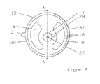
- Characteristic is how in the Figures 2 . 3 and 4 shown that the drive shaft 2 on the one hand in the bearing bore 14 on the balance piston 13 and On the other hand, is mounted in a bearing seat 35 in the bearing housing 34 of the pump housing 1, wherein both between the bearing bore 14 on the balance piston 13 and the pressure kidney 9 on the balance piston 13, as in the FIG. 5 shown, and also between the bearing seat 35 in the bearing housing 34 of the pump housing 1 and the pressure kidney 9 in the bearing housing 34 of the pump housing 1, as in the FIG.
- This arrangement ensures, under operating conditions with minimal manufacturing effort, a robust, reliable, trouble-free, safe and low-friction displacement of the compensating piston 13 while at the same time optimally sealing the compensating piston 13 in the compensating piston guide 12.
- This control piston sealing ring 33 causes a reliable, störunan administrate, dynamic displacement of the balance piston thirteenth
- the pump housing as in the FIGS. 1 to 4 shown, constructed in a modular manner and sandwiched together, and from a bearing housing 34 with a bearing seat 35, a seal seat 36, a suction kidney 8, connected to this return flow channel 26, connected to the suction kidney 8 Saugan gleichkanal 10 and between the chamber with the Sealing seat 36 and the suction kidney 8 and the Saugan gleichkanal 10 arranged remindströmkanal 26, a pressure kidney 9 and connected to this pressure connection channel 11 and connected to the pressure kidney 9 and or the pressure port channel 11 pressure channel 18, a seal seat 36 for receiving a shaft seal 38, a Ring groove 37 for receiving a sealing ring 39 (O-ring) and a plurality of threaded holes 40 consists.
- a work casing 41 having through holes 42 is disposed adjacent thereto; in which the wheelset 3 is mounted, this work housing 41 is adjacent a control housing 43 with mutually arranged annular grooves 37; a plurality of through holes 42, the balance piston guide 12 and the control piston guide 15 is disposed adjacent to this control housing 43 then a housing cover 44, again with through holes 42, and in the final assembly state in the annular grooves 37 each have a sealing ring 39 (O-rings) is arranged , wherein the through holes 42 in the final assembly state are aligned with each other, and the sandwich-shaped pump housing 1 is clamped over the entire surface by means of dowel sleeves 45 and through-connection screws 46 along the side walls facing each other.
- O-rings sealing ring 39
Landscapes
- Engineering & Computer Science (AREA)
- Mechanical Engineering (AREA)
- General Engineering & Computer Science (AREA)
- Rotary Pumps (AREA)
- Reciprocating Pumps (AREA)
- Details And Applications Of Rotary Liquid Pumps (AREA)
Applications Claiming Priority (1)
| Application Number | Priority Date | Filing Date | Title |
|---|---|---|---|
| DE201010008062 DE102010008062B3 (de) | 2010-02-16 | 2010-02-16 | Zahnringpumpe |
Publications (2)
| Publication Number | Publication Date |
|---|---|
| EP2357362A2 true EP2357362A2 (fr) | 2011-08-17 |
| EP2357362A3 EP2357362A3 (fr) | 2016-11-23 |
Family
ID=43629307
Family Applications (1)
| Application Number | Title | Priority Date | Filing Date |
|---|---|---|---|
| EP11000603.8A Withdrawn EP2357362A3 (fr) | 2010-02-16 | 2011-01-26 | Machine à engrenage d'anneau |
Country Status (2)
| Country | Link |
|---|---|
| EP (1) | EP2357362A3 (fr) |
| DE (1) | DE102010008062B3 (fr) |
Cited By (5)
| Publication number | Priority date | Publication date | Assignee | Title |
|---|---|---|---|---|
| CN103075338A (zh) * | 2011-10-25 | 2013-05-01 | 丹佛斯公司 | 叶片单元机 |
| WO2014117889A3 (fr) * | 2013-01-29 | 2014-10-23 | Robert Bosch Gmbh | Pompe à engrenages intérieurs |
| US8951027B2 (en) | 2011-10-25 | 2015-02-10 | Danfoss A/S | Vane cell machine |
| WO2015026409A1 (fr) * | 2013-08-22 | 2015-02-26 | Eaton Corporation | Unité de commande hydraulique munie d'une plaque d'interface disposée entre le boîtier et la pompe |
| CN110195702A (zh) * | 2019-07-03 | 2019-09-03 | 宝鸡中车时代工程机械有限公司 | 用于轨道工程车辆传动箱的浮动密封式内啮合摆线润滑泵 |
Families Citing this family (2)
| Publication number | Priority date | Publication date | Assignee | Title |
|---|---|---|---|---|
| DE102015112664C5 (de) | 2015-07-31 | 2022-11-17 | Ebm-Papst St. Georgen Gmbh & Co. Kg | Zahnringpumpe |
| DE102018105121A1 (de) * | 2018-03-06 | 2019-09-12 | Schwäbische Hüttenwerke Automotive GmbH | Unterstützungstaschen |
Citations (3)
| Publication number | Priority date | Publication date | Assignee | Title |
|---|---|---|---|---|
| DE4220554A1 (de) | 1992-06-24 | 1994-01-13 | Bosch Gmbh Robert | Aggregat zum Fördern von Kraftstoff aus einem Vorratstank zur Brennkraftmaschine eines Kraftfahrzeuges |
| DE19826367C2 (de) | 1998-06-12 | 2000-05-18 | Geraete & Pumpenbau Gmbh | Innenzahnradpumpe |
| DE102008054758A1 (de) | 2008-12-16 | 2010-06-17 | Robert Bosch Gmbh | Förderaggregat |
Family Cites Families (4)
| Publication number | Priority date | Publication date | Assignee | Title |
|---|---|---|---|---|
| DE1196507B (de) * | 1958-12-23 | 1965-07-08 | Bosch Gmbh Robert | Zahnradpumpe oder -motor |
| DE2532091A1 (de) * | 1975-07-18 | 1977-02-03 | Hohenzollern Huettenverwalt | Innenlaeufer-zahnradpumpe mit stromregelventil fuer hydrolenkpumpen |
| DE3402710A1 (de) * | 1984-01-26 | 1985-08-08 | Siegfried Dipl.-Ing. 7960 Aulendorf Eisenmann | Hydraulische kreiskolbenmaschine |
| EP2143935B1 (fr) * | 2008-07-08 | 2011-01-19 | Continental Automotive GmbH | Unité de pompe destinée à l'écoulement d'un fluide |
-
2010
- 2010-02-16 DE DE201010008062 patent/DE102010008062B3/de not_active Expired - Fee Related
-
2011
- 2011-01-26 EP EP11000603.8A patent/EP2357362A3/fr not_active Withdrawn
Patent Citations (3)
| Publication number | Priority date | Publication date | Assignee | Title |
|---|---|---|---|---|
| DE4220554A1 (de) | 1992-06-24 | 1994-01-13 | Bosch Gmbh Robert | Aggregat zum Fördern von Kraftstoff aus einem Vorratstank zur Brennkraftmaschine eines Kraftfahrzeuges |
| DE19826367C2 (de) | 1998-06-12 | 2000-05-18 | Geraete & Pumpenbau Gmbh | Innenzahnradpumpe |
| DE102008054758A1 (de) | 2008-12-16 | 2010-06-17 | Robert Bosch Gmbh | Förderaggregat |
Cited By (11)
| Publication number | Priority date | Publication date | Assignee | Title |
|---|---|---|---|---|
| CN103075338A (zh) * | 2011-10-25 | 2013-05-01 | 丹佛斯公司 | 叶片单元机 |
| US8951027B2 (en) | 2011-10-25 | 2015-02-10 | Danfoss A/S | Vane cell machine |
| US9279424B2 (en) | 2011-10-25 | 2016-03-08 | Danfoss A/S | Vane cell machine having plates containing axial moving inserts bearing against the rotor |
| CN103075338B (zh) * | 2011-10-25 | 2016-12-28 | 丹佛斯公司 | 叶片单元机 |
| WO2014117889A3 (fr) * | 2013-01-29 | 2014-10-23 | Robert Bosch Gmbh | Pompe à engrenages intérieurs |
| CN104956087A (zh) * | 2013-01-29 | 2015-09-30 | 罗伯特·博世有限公司 | 内齿轮泵 |
| JP2016504531A (ja) * | 2013-01-29 | 2016-02-12 | ローベルト ボッシュ ゲゼルシャフト ミット ベシュレンクテル ハフツング | 内接型ギヤポンプ |
| US9765779B2 (en) | 2013-01-29 | 2017-09-19 | Robert Bosch Gmbh | Internal gear pump having a rotationally fixed axial disk |
| WO2015026409A1 (fr) * | 2013-08-22 | 2015-02-26 | Eaton Corporation | Unité de commande hydraulique munie d'une plaque d'interface disposée entre le boîtier et la pompe |
| CN110195702A (zh) * | 2019-07-03 | 2019-09-03 | 宝鸡中车时代工程机械有限公司 | 用于轨道工程车辆传动箱的浮动密封式内啮合摆线润滑泵 |
| CN110195702B (zh) * | 2019-07-03 | 2024-03-19 | 宝鸡中车时代工程机械有限公司 | 用于轨道工程车辆传动箱的浮动密封式内啮合摆线润滑泵 |
Also Published As
| Publication number | Publication date |
|---|---|
| DE102010008062B3 (de) | 2011-06-22 |
| EP2357362A3 (fr) | 2016-11-23 |
Similar Documents
| Publication | Publication Date | Title |
|---|---|---|
| EP2921703B1 (fr) | Unité pompes-moteur | |
| EP2921702B1 (fr) | Unité pompes-moteur | |
| DE102011107157B4 (de) | Zahnringpumpe | |
| DE102010008062B3 (de) | Zahnringpumpe | |
| DE102008016212B4 (de) | Ausgeglichene Flügelzellenpumpe variabler Förderleistung/Verdrängung mit schwimmenden Stirnflächendichtungen und vorgespannten Flügeldichtungen | |
| WO2012034619A1 (fr) | Machine à pistons axiaux | |
| DE202011052114U1 (de) | Innenzahnradpumpe | |
| EP2510192B1 (fr) | Machine hydrostatique à pistons radiaux | |
| DE102005037035A1 (de) | Trochoidenpumpe | |
| DE1266134B (de) | Zahnradpumpe | |
| DE102005041579A1 (de) | Innenzahnradpumpe mit Füllstück | |
| EP3230592A1 (fr) | Pompe gérotor | |
| DE102008003240B4 (de) | Förderaggregat | |
| EP1785622B1 (fr) | Pompe hydraulique | |
| EP1922487B1 (fr) | Pompe volumétrique présentant un volume de transport variable | |
| EP1026401B1 (fr) | Pompe hydrostatique | |
| EP2119869A2 (fr) | Hydromachine | |
| EP2286088B1 (fr) | Pompe | |
| DE102006025532B4 (de) | Verstellbare Verdrängerpumpe | |
| DE102013224660A1 (de) | Flügelzellenmaschine mit definiertem Druck in den Hinterflügelräumen | |
| WO2007025790A1 (fr) | Pompe rotative | |
| DE102014220205A1 (de) | Pumpenanordnung mit Hauptpumpe und Hilfspumpe | |
| DD152393A1 (de) | Hydrostatische zahnradmaschine | |
| DD257103A1 (de) | Hydrostatische radialkolbenmaschine | |
| EP1293673A2 (fr) | Flügelzellenpumpe |
Legal Events
| Date | Code | Title | Description |
|---|---|---|---|
| PUAI | Public reference made under article 153(3) epc to a published international application that has entered the european phase |
Free format text: ORIGINAL CODE: 0009012 |
|
| AK | Designated contracting states |
Kind code of ref document: A2 Designated state(s): AL AT BE BG CH CY CZ DE DK EE ES FI FR GB GR HR HU IE IS IT LI LT LU LV MC MK MT NL NO PL PT RO RS SE SI SK SM TR |
|
| AX | Request for extension of the european patent |
Extension state: BA ME |
|
| PUAL | Search report despatched |
Free format text: ORIGINAL CODE: 0009013 |
|
| AK | Designated contracting states |
Kind code of ref document: A3 Designated state(s): AL AT BE BG CH CY CZ DE DK EE ES FI FR GB GR HR HU IE IS IT LI LT LU LV MC MK MT NL NO PL PT RO RS SE SI SK SM TR |
|
| AX | Request for extension of the european patent |
Extension state: BA ME |
|
| RIC1 | Information provided on ipc code assigned before grant |
Ipc: F04C 15/06 20060101ALI20161018BHEP Ipc: F04C 2/10 20060101AFI20161018BHEP |
|
| STAA | Information on the status of an ep patent application or granted ep patent |
Free format text: STATUS: THE APPLICATION IS DEEMED TO BE WITHDRAWN |
|
| 18D | Application deemed to be withdrawn |
Effective date: 20170524 |