EP2357534A2 - Entwicklerzufuhrbehalter - Google Patents
Entwicklerzufuhrbehalter Download PDFInfo
- Publication number
- EP2357534A2 EP2357534A2 EP11165463A EP11165463A EP2357534A2 EP 2357534 A2 EP2357534 A2 EP 2357534A2 EP 11165463 A EP11165463 A EP 11165463A EP 11165463 A EP11165463 A EP 11165463A EP 2357534 A2 EP2357534 A2 EP 2357534A2
- Authority
- EP
- European Patent Office
- Prior art keywords
- developer
- developer supply
- supply container
- gear
- container
- Prior art date
- Legal status (The legal status is an assumption and is not a legal conclusion. Google has not performed a legal analysis and makes no representation as to the accuracy of the status listed.)
- Withdrawn
Links
- 238000007599 discharging Methods 0.000 claims description 23
- 239000000463 material Substances 0.000 claims description 16
- 239000000853 adhesive Substances 0.000 claims description 3
- 230000001070 adhesive effect Effects 0.000 claims description 3
- 239000002390 adhesive tape Substances 0.000 claims description 3
- 239000011347 resin Substances 0.000 claims description 3
- 229920005989 resin Polymers 0.000 claims description 3
- 230000005540 biological transmission Effects 0.000 abstract description 28
- 230000002159 abnormal effect Effects 0.000 abstract description 2
- 238000003756 stirring Methods 0.000 description 36
- 230000007246 mechanism Effects 0.000 description 35
- 230000008878 coupling Effects 0.000 description 31
- 238000010168 coupling process Methods 0.000 description 31
- 238000005859 coupling reaction Methods 0.000 description 31
- 238000007789 sealing Methods 0.000 description 27
- 238000000034 method Methods 0.000 description 25
- 230000008569 process Effects 0.000 description 16
- 230000002093 peripheral effect Effects 0.000 description 13
- 210000000078 claw Anatomy 0.000 description 9
- 230000015572 biosynthetic process Effects 0.000 description 7
- 239000000126 substance Substances 0.000 description 7
- 230000001105 regulatory effect Effects 0.000 description 6
- 238000005259 measurement Methods 0.000 description 5
- 239000004793 Polystyrene Substances 0.000 description 4
- 238000004891 communication Methods 0.000 description 4
- 238000011161 development Methods 0.000 description 4
- 230000000694 effects Effects 0.000 description 4
- 238000001746 injection moulding Methods 0.000 description 4
- 229920002223 polystyrene Polymers 0.000 description 4
- 230000004048 modification Effects 0.000 description 3
- 238000012986 modification Methods 0.000 description 3
- 230000003287 optical effect Effects 0.000 description 3
- 239000012261 resinous substance Substances 0.000 description 3
- 229930182556 Polyacetal Natural products 0.000 description 2
- 230000008859 change Effects 0.000 description 2
- 229920001971 elastomer Polymers 0.000 description 2
- 239000004973 liquid crystal related substance Substances 0.000 description 2
- 239000002245 particle Substances 0.000 description 2
- 229920000728 polyester Polymers 0.000 description 2
- 229920006324 polyoxymethylene Polymers 0.000 description 2
- 230000009467 reduction Effects 0.000 description 2
- 238000000926 separation method Methods 0.000 description 2
- 238000012546 transfer Methods 0.000 description 2
- 238000003466 welding Methods 0.000 description 2
- 229920006311 Urethane elastomer Polymers 0.000 description 1
- 238000004026 adhesive bonding Methods 0.000 description 1
- 238000004140 cleaning Methods 0.000 description 1
- 239000011248 coating agent Substances 0.000 description 1
- 238000000576 coating method Methods 0.000 description 1
- 230000001276 controlling effect Effects 0.000 description 1
- 230000002950 deficient Effects 0.000 description 1
- 238000000151 deposition Methods 0.000 description 1
- 230000009977 dual effect Effects 0.000 description 1
- 239000000806 elastomer Substances 0.000 description 1
- 230000008030 elimination Effects 0.000 description 1
- 238000003379 elimination reaction Methods 0.000 description 1
- 239000010419 fine particle Substances 0.000 description 1
- 239000011521 glass Substances 0.000 description 1
- 239000000203 mixture Substances 0.000 description 1
- 239000000843 powder Substances 0.000 description 1
- 238000003825 pressing Methods 0.000 description 1
- 238000012545 processing Methods 0.000 description 1
- 230000001737 promoting effect Effects 0.000 description 1
- 230000004044 response Effects 0.000 description 1
- 229920002379 silicone rubber Polymers 0.000 description 1
- 238000009751 slip forming Methods 0.000 description 1
- 238000011144 upstream manufacturing Methods 0.000 description 1
Images








Classifications
-
- G—PHYSICS
- G03—PHOTOGRAPHY; CINEMATOGRAPHY; ANALOGOUS TECHNIQUES USING WAVES OTHER THAN OPTICAL WAVES; ELECTROGRAPHY; HOLOGRAPHY
- G03G—ELECTROGRAPHY; ELECTROPHOTOGRAPHY; MAGNETOGRAPHY
- G03G15/00—Apparatus for electrographic processes using a charge pattern
- G03G15/06—Apparatus for electrographic processes using a charge pattern for developing
- G03G15/08—Apparatus for electrographic processes using a charge pattern for developing using a solid developer, e.g. powder developer
- G03G15/0822—Arrangements for preparing, mixing, supplying or dispensing developer
- G03G15/0865—Arrangements for supplying new developer
- G03G15/0867—Arrangements for supplying new developer cylindrical developer cartridges, e.g. toner bottles for the developer replenishing opening
- G03G15/087—Developer cartridges having a longitudinal rotational axis, around which at least one part is rotated when mounting or using the cartridge
- G03G15/0872—Developer cartridges having a longitudinal rotational axis, around which at least one part is rotated when mounting or using the cartridge the developer cartridges being generally horizontally mounted parallel to its longitudinal rotational axis
-
- G—PHYSICS
- G03—PHOTOGRAPHY; CINEMATOGRAPHY; ANALOGOUS TECHNIQUES USING WAVES OTHER THAN OPTICAL WAVES; ELECTROGRAPHY; HOLOGRAPHY
- G03G—ELECTROGRAPHY; ELECTROPHOTOGRAPHY; MAGNETOGRAPHY
- G03G15/00—Apparatus for electrographic processes using a charge pattern
- G03G15/06—Apparatus for electrographic processes using a charge pattern for developing
- G03G15/08—Apparatus for electrographic processes using a charge pattern for developing using a solid developer, e.g. powder developer
- G03G15/09—Apparatus for electrographic processes using a charge pattern for developing using a solid developer, e.g. powder developer using magnetic brush
- G03G15/0921—Details concerning the magnetic brush roller structure, e.g. magnet configuration
- G03G15/0935—Details concerning the magnetic brush roller structure, e.g. magnet configuration relating to bearings or driving mechanism
-
- G—PHYSICS
- G03—PHOTOGRAPHY; CINEMATOGRAPHY; ANALOGOUS TECHNIQUES USING WAVES OTHER THAN OPTICAL WAVES; ELECTROGRAPHY; HOLOGRAPHY
- G03G—ELECTROGRAPHY; ELECTROPHOTOGRAPHY; MAGNETOGRAPHY
- G03G15/00—Apparatus for electrographic processes using a charge pattern
- G03G15/06—Apparatus for electrographic processes using a charge pattern for developing
- G03G15/08—Apparatus for electrographic processes using a charge pattern for developing using a solid developer, e.g. powder developer
-
- G—PHYSICS
- G03—PHOTOGRAPHY; CINEMATOGRAPHY; ANALOGOUS TECHNIQUES USING WAVES OTHER THAN OPTICAL WAVES; ELECTROGRAPHY; HOLOGRAPHY
- G03G—ELECTROGRAPHY; ELECTROPHOTOGRAPHY; MAGNETOGRAPHY
- G03G15/00—Apparatus for electrographic processes using a charge pattern
-
- G—PHYSICS
- G03—PHOTOGRAPHY; CINEMATOGRAPHY; ANALOGOUS TECHNIQUES USING WAVES OTHER THAN OPTICAL WAVES; ELECTROGRAPHY; HOLOGRAPHY
- G03G—ELECTROGRAPHY; ELECTROPHOTOGRAPHY; MAGNETOGRAPHY
- G03G15/00—Apparatus for electrographic processes using a charge pattern
- G03G15/06—Apparatus for electrographic processes using a charge pattern for developing
- G03G15/08—Apparatus for electrographic processes using a charge pattern for developing using a solid developer, e.g. powder developer
- G03G15/0806—Apparatus for electrographic processes using a charge pattern for developing using a solid developer, e.g. powder developer on a donor element, e.g. belt, roller
- G03G15/0808—Apparatus for electrographic processes using a charge pattern for developing using a solid developer, e.g. powder developer on a donor element, e.g. belt, roller characterised by the developer supplying means, e.g. structure of developer supply roller
-
- G—PHYSICS
- G03—PHOTOGRAPHY; CINEMATOGRAPHY; ANALOGOUS TECHNIQUES USING WAVES OTHER THAN OPTICAL WAVES; ELECTROGRAPHY; HOLOGRAPHY
- G03G—ELECTROGRAPHY; ELECTROPHOTOGRAPHY; MAGNETOGRAPHY
- G03G15/00—Apparatus for electrographic processes using a charge pattern
- G03G15/06—Apparatus for electrographic processes using a charge pattern for developing
- G03G15/08—Apparatus for electrographic processes using a charge pattern for developing using a solid developer, e.g. powder developer
- G03G15/0822—Arrangements for preparing, mixing, supplying or dispensing developer
- G03G15/0865—Arrangements for supplying new developer
-
- G—PHYSICS
- G03—PHOTOGRAPHY; CINEMATOGRAPHY; ANALOGOUS TECHNIQUES USING WAVES OTHER THAN OPTICAL WAVES; ELECTROGRAPHY; HOLOGRAPHY
- G03G—ELECTROGRAPHY; ELECTROPHOTOGRAPHY; MAGNETOGRAPHY
- G03G15/00—Apparatus for electrographic processes using a charge pattern
- G03G15/06—Apparatus for electrographic processes using a charge pattern for developing
- G03G15/08—Apparatus for electrographic processes using a charge pattern for developing using a solid developer, e.g. powder developer
- G03G15/0822—Arrangements for preparing, mixing, supplying or dispensing developer
- G03G15/0877—Arrangements for metering and dispensing developer from a developer cartridge into the development unit
-
- G—PHYSICS
- G03—PHOTOGRAPHY; CINEMATOGRAPHY; ANALOGOUS TECHNIQUES USING WAVES OTHER THAN OPTICAL WAVES; ELECTROGRAPHY; HOLOGRAPHY
- G03G—ELECTROGRAPHY; ELECTROPHOTOGRAPHY; MAGNETOGRAPHY
- G03G15/00—Apparatus for electrographic processes using a charge pattern
- G03G15/06—Apparatus for electrographic processes using a charge pattern for developing
- G03G15/08—Apparatus for electrographic processes using a charge pattern for developing using a solid developer, e.g. powder developer
- G03G15/0822—Arrangements for preparing, mixing, supplying or dispensing developer
- G03G15/0877—Arrangements for metering and dispensing developer from a developer cartridge into the development unit
- G03G15/0881—Sealing of developer cartridges
- G03G15/0886—Sealing of developer cartridges by mechanical means, e.g. shutter, plug
-
- G—PHYSICS
- G03—PHOTOGRAPHY; CINEMATOGRAPHY; ANALOGOUS TECHNIQUES USING WAVES OTHER THAN OPTICAL WAVES; ELECTROGRAPHY; HOLOGRAPHY
- G03G—ELECTROGRAPHY; ELECTROPHOTOGRAPHY; MAGNETOGRAPHY
- G03G15/00—Apparatus for electrographic processes using a charge pattern
- G03G15/06—Apparatus for electrographic processes using a charge pattern for developing
- G03G15/08—Apparatus for electrographic processes using a charge pattern for developing using a solid developer, e.g. powder developer
- G03G15/0822—Arrangements for preparing, mixing, supplying or dispensing developer
- G03G15/0887—Arrangements for conveying and conditioning developer in the developing unit, e.g. agitating, removing impurities or humidity
- G03G15/0889—Arrangements for conveying and conditioning developer in the developing unit, e.g. agitating, removing impurities or humidity for agitation or stirring
-
- G—PHYSICS
- G03—PHOTOGRAPHY; CINEMATOGRAPHY; ANALOGOUS TECHNIQUES USING WAVES OTHER THAN OPTICAL WAVES; ELECTROGRAPHY; HOLOGRAPHY
- G03G—ELECTROGRAPHY; ELECTROPHOTOGRAPHY; MAGNETOGRAPHY
- G03G21/00—Arrangements not provided for by groups G03G13/00 - G03G19/00, e.g. cleaning, elimination of residual charge
- G03G21/16—Mechanical means for facilitating the maintenance of the apparatus, e.g. modular arrangements
- G03G21/1661—Mechanical means for facilitating the maintenance of the apparatus, e.g. modular arrangements means for handling parts of the apparatus in the apparatus
- G03G21/1676—Mechanical means for facilitating the maintenance of the apparatus, e.g. modular arrangements means for handling parts of the apparatus in the apparatus for the developer unit
-
- B—PERFORMING OPERATIONS; TRANSPORTING
- B41—PRINTING; LINING MACHINES; TYPEWRITERS; STAMPS
- B41J—TYPEWRITERS; SELECTIVE PRINTING MECHANISMS, i.e. MECHANISMS PRINTING OTHERWISE THAN FROM A FORME; CORRECTION OF TYPOGRAPHICAL ERRORS
- B41J2/00—Typewriters or selective printing mechanisms characterised by the printing or marking process for which they are designed
- B41J2/005—Typewriters or selective printing mechanisms characterised by the printing or marking process for which they are designed characterised by bringing liquid or particles selectively into contact with a printing material
- B41J2/01—Ink jet
- B41J2/17—Ink jet characterised by ink handling
- B41J2/18—Ink recirculation systems
- B41J2/185—Ink-collectors; Ink-catchers
-
- G—PHYSICS
- G03—PHOTOGRAPHY; CINEMATOGRAPHY; ANALOGOUS TECHNIQUES USING WAVES OTHER THAN OPTICAL WAVES; ELECTROGRAPHY; HOLOGRAPHY
- G03G—ELECTROGRAPHY; ELECTROPHOTOGRAPHY; MAGNETOGRAPHY
- G03G2215/00—Apparatus for electrophotographic processes
- G03G2215/06—Developing structures, details
- G03G2215/066—Toner cartridge or other attachable and detachable container for supplying developer material to replace the used material
- G03G2215/0663—Toner cartridge or other attachable and detachable container for supplying developer material to replace the used material having a longitudinal rotational axis, around which at least one part is rotated when mounting or using the cartridge
-
- G—PHYSICS
- G03—PHOTOGRAPHY; CINEMATOGRAPHY; ANALOGOUS TECHNIQUES USING WAVES OTHER THAN OPTICAL WAVES; ELECTROGRAPHY; HOLOGRAPHY
- G03G—ELECTROGRAPHY; ELECTROPHOTOGRAPHY; MAGNETOGRAPHY
- G03G2215/00—Apparatus for electrophotographic processes
- G03G2215/06—Developing structures, details
- G03G2215/066—Toner cartridge or other attachable and detachable container for supplying developer material to replace the used material
- G03G2215/0663—Toner cartridge or other attachable and detachable container for supplying developer material to replace the used material having a longitudinal rotational axis, around which at least one part is rotated when mounting or using the cartridge
- G03G2215/0665—Generally horizontally mounting of said toner cartridge parallel to its longitudinal rotational axis
- G03G2215/067—Toner discharging opening covered by arcuate shutter
-
- G—PHYSICS
- G03—PHOTOGRAPHY; CINEMATOGRAPHY; ANALOGOUS TECHNIQUES USING WAVES OTHER THAN OPTICAL WAVES; ELECTROGRAPHY; HOLOGRAPHY
- G03G—ELECTROGRAPHY; ELECTROPHOTOGRAPHY; MAGNETOGRAPHY
- G03G2215/00—Apparatus for electrophotographic processes
- G03G2215/08—Details of powder developing device not concerning the development directly
- G03G2215/0802—Arrangements for agitating or circulating developer material
- G03G2215/085—Stirring member in developer container
Definitions
- the user rotates the developer supply container through a predetermined angle, by which the developer supply container (developer supply) becomes operable. More particularly, by the rotation of the developer supply container, an opening provided in an outer surface of the developer supply container is brought into communication with an opening provided in the image forming apparatus side, thus enabling the supply of the developer.
- the handle 2 may be mechanically coupled with the container body 1a, or may be attached to the container body 1a with the use of screws. Further, it may be fixed to the container body 1a by gluing or welding. All that is required of the method for fixing the handle 2 to the container body 1a is that the method is capable of securing the handle 2 to the container body 1a so that the handle 2 does not become loose or separated from the container body 1a when the developer supply container 1 is mounted or dismounted. In this embodiment, the handle 2 is fixed to the container body 1a by being mechanically coupled with the container body 1a.
- the developer discharge opening 1b may be hermetically sealed by welding a piece of sealing film formed of resin, to the area of the wall of the container body 1a, which surrounds the developer discharge opening 1b In this case, this sealing film is peeled away to unseal the developer discharge opening 1b (developer supply container 1).
- the developer supply container 1 is provided with a drive transmitting means, which engages with the driving gear member 12 and transmits to the conveying member 4 the rotational driving force received from the driving gear member 12.
- the developer supply container 1 is to be rotated by the preset angle into its operative position (replenishment position), with the use of the handle 2.
- the drive transmitting means and driving gear member 12 are not in engagement with each other (disengaged state); there is a certain amount of distance between the two in terms of the circumferential direction of the developer supply container 1. Then, as the developer supply container 1 is rotated with the use of the handle 2, the drive transmitting means and the driving gear member 12 meet and engage with each other (engaged state).
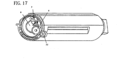
- the first gear 5 (driving force relaying member), as the drive transmitting means, which is in connection with the conveying member 4, is supported by its shaft portion by one of the lengthwise ends of the container body 1a so that the first gear 5 is rotatable about the rotational axis (approximate rotational axis) of the developer supply container 1.
- the first gear 5 is coaxially rotatable with the conveying member 4.
- the third gear 6' which is an integral part of the second gear 6, and the first gear 5 which is in mesh with the second gear 6 and drivable by the second gear 6, rotate, whereby the conveying member 4 in the container body 1a is rotated.
- the drive transmitting means may be made up of the second gear 6 alone, that is, without the first gear 5.
- the second gear 6 is supported by a shaft attached to the portion of the container body 1a, which is offset from the rotational axis of the container body 1a.
- the second gear 6 is connected to the conveying member 4 so that it coaxially rotates with the conveying member 4.
- first and second gears 5 and 6 have the function of satisfactorily transmitting the driving force transmitted thereto from the developer receiving device 10.
- polyacetal is employed as their material, and they are made by injection molding.
- the drive transmitting means is utilized to generate the force for pulling the container body 1a to automatically rotate the container body 1a toward its operative position.
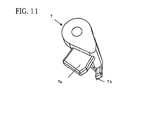
- the first gear 5 is provided with a disengagement projection 5a ( Figures 4 , 9 , etc.) as an unlocking portion, which protrudes from the end surface of the first gear 5.
- the disengagement projection 5a is structured so that as the first gear 5 rotates relative to the developer supply container 1 while the developer supply container 1 is in the operative position (refilling position), it collides with the disengaging portion 7a of the locking member 7.
- the torque generating mechanism in this embodiment does not completely lock the first gear 5, that is, does not completely prevent the first gear 5 from rotating relative to the container body 1a. Rather, it increases the rotational load to such an amount that allows the first gear 5 to rotate relative to the developer supply container 1 once the operation for rotating the developer supply container 1 into its operative position is completed.
- the developer receiving device 10 is provided with a disengagement projection 10f, which is attached to such a portion of the developer receiving device 10 that after the rotation of the developer supply container 1 into its operative position, the disengagement projection 10f is in the position in which it acts on (disengages) the disengaging portion 7a of the locking member 7.
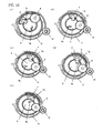
- Figures 8(b) and 9(b) are sectional views of the developer supply container 1 and developer receiving device 10, which are for describing the relationship among the developer discharge opening 1b, developer receiving opening 10b, and developing device shutter 11.
- Figures 8(c) and 9(c) are sectional views of the developer supply container 1 and developer receiving device 10, which are for describing the relationship among the driving gear member 12, first gear 5, and second gear 6.
- Figures 8(d) and 9(d) are sectional views of the developer supply container 1 and developer receiving device 10, which are for describing primarily the relationship among the developing device shutter 11 and the portions of the container body 1a, which move with the developing device shutter 11.
- the container body of the developer supply container is cylindrical.
- the shape of the container body does not need to be limited to the cylindrical one.
- the container body of the developer supply container may be shaped as shown in Figure 20 , in which the cross section of the container body appears as if a small segment has been cut away from a circle.
- the rotational axis of the developer supply container coincides with the center of the arc of the cross section near the developer discharge opening, which also roughly coincides with the rotational axis of each of the abovementioned shutters.
- the number of the gears for transmitting driving force to the first gear 5 is an odd number, and the rotational direction of the gear 6a, which is in mesh with the driving gear member 12, is the same as the direction in which the developer supply container 1 is automatically rotated.
- the force which automatically rotated the container body 1a through the gear 6a as driving force is inputted into the driving gear member 12 which is in mesh with the gear 6a, can be generated as in the first embodiment.
- the first embodiment is preferable.
- a first friction wheel 5, a second friction wheel 6, and a third friction wheel are employed as the drive transmitting means.
- Each friction wheel is formed of a substance which is high in friction, so that the friction wheel is substantial in the friction of its peripheral surface, or the contact surface.
- the third friction wheel is an integral part of the second friction wheel 6 and is coaxial with the second friction wheel 6.
- the driving gear member 12 of the developer receiving device is also a friction wheel.
- the developer supply container can be automatically rotated as in the first embodiment.
- this embodiment is different from the first embodiment in that the structure in this embodiment is provided with a large gear L, that is, an additional gear, as one of the driving force transmitting members, which meshes with the driving gear member 12 of the developer receiving device 10.
- a large gear L that is, an additional gear
- the large gear L is attached after the first and second gears 5 and 6 are attached. In other words, it is attached to one of the end walls of the container body 1a.
- Figure 22 was drawn to show the inward side of the large gear L, showing the manner in which the gears are in mesh among themselves, and the directions in which the gears rotate.
- the strength of the projection 5c is set so that the projection 5c will be broken by the driving force inputted to the driving gear member 12 after the completion of the automatic rotation of the developer supply container 1.
- the projection 5c is broken, allowing thereby the first gear 5 to rotate relative to the container body 1a.
- the structural arrangement in this embodiment is such that the rotational load for the first gear 5 is eliminated by breaking off the projection 5c of the first gear 5. Therefore, it is possible that after the projection 5c is broken off (separated from developer supply container 1), it will fall into the developer receiving device 10. Therefore, the structural arrangement in the first embodiment, which does not have such a possibility, is preferable.
- the developer supply container 1 is automatically rotated, as in the first embodiment, as driving force is inputted into the driving gear member 12.
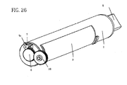
- FIG. 24 a developer supply container 1 according to embodiment 6 will be described.
- the structure of the container of this embodiment is fundamentally the same as that of embodiment 1, and therefore, the description will be made as to the structure different from that of embodiment 1.
- the same reference numerals are assigned to the elements having the corresponding functions.
- a component such as the ring 14 employed in the first embodiment, is unnecessary, making it possible to reduce the cost of the developer supply container 1.
- the timing which with the developer discharge opening 1b becomes connected to the developer receiving opening 10b deviates from the timing with which the unlocking timing, because of the nonuniformity in the measurements and positioning of the various members of the developer supply container 1 and developer receiving device 10. Therefore, the structural arrangement in the first embodiment, which has no possibility of the occurrence of such a problem, is preferable.
- the drive transmitting means is not provided with the second and third gears; it is provided with only the first gear 5.
- the first gear 5 is an integral part of the locking member 9, and there is no ring 14. The first gear 5 is completely locked so that it cannot rotate relative to the container body 1a.
- the first gear 5 engages with the driving gear member 12 of the developer receiving device 10 at the end of the process of mounting the developer supply container 1 into the developer receiving device 10. At this point in time, driving force is inputted into the driving gear member 12. As the driving force is inputted, rotational force is generated in the container body 1a, because the first gear 5 is locked to the container body 1a by the locking claw 7 as the suppressing means.
- the container body 1a automatically rotates as in the first embodiment.
- the developer discharge opening 1b becomes aligned with the developer receiving opening 10b, and at the same time, the disengaging portion 7b of the locking member 7 collides with the disengagement projection 10a of the developer receiving device 10, being thereby pushed up in the direction indicated by the arrow mark B. Therefore, the first gear 5 is unlocked form the container body 1a.
- the first gear 5 and locking member 9 which are employed in the first embodiment are integrated into a single component, and the locking portion 7b of the locking member 7 is caught by this component, more specifically, the locking portion (9) of this component.
- the point at which the driving force transmitting means is locked may be any point in the stirring system. For example, it may be locked at one of the teeth of the first gear 5.
- the portion which provides the container body 1a with rotational force while the developer supply container is pulled in, as described above, is the shaft with which the second gear 6 is supported, and the greater the distance between this shaft and the rotational axis of the container body 1a, the easier to rotate the container body 1a, and therefore, the smaller the amount of the rotational load which the second gear 6 is required to have.
- the timing which with the developer discharge opening 1b becomes connected to the developer receiving opening 10b will deviate from the timing with which the unlocking timing, because of the nonuniformity in the measurements and positioning of the various members of the developer supply container 1 and developer receiving device 10.
- the first gear 5 comes into contact with the driving gear member 12 from the direction parallel to the axial lines of the two gears (first gear 5 and driving gear member 12). Therefore, it is possible that the misalignment of teeth between the two gears will make it difficult to fully insert the developer supply container 1. Therefore, the structural arrangement in the first embodiment, which has no possibility of the occurrence of such a problem, is preferable.
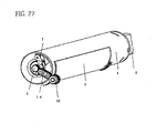
- FIG. 27 a developer supply container 1 according to embodiment 8 will be described.
- the structure of the container of this embodiment is fundamentally the same as that of embodiment 1, and therefore, the description will be made as to the structure different from that of embodiment 1.
- the same reference numerals are assigned to the elements having the corresponding functions.
- both the inward surface of the driving force transmitting belt 16, and the peripheral surface of each pulley may be toothed to provide a higher level of insurance that the belt 16 and pulleys do not slip relative to each other.
- the first gear 5 is kept completely locked.
- the developer supply container 1 may be structured so that the first gear 5 is provided with a certain amount of rotational load instead of being completely locked.
- the locking member 7 is freed from the locking member 9 by the disengaging projection of the locking member 9 which rotates with the first gear 5 relative to the container body 1, after the completion of the automatic rotation of the developer supply container 1. Therefore, the developer discharge opening 1b can be properly connected with the developer receiving opening 10b.
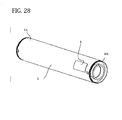
- a helical screw portion 301 ( Figure 29 ) is formed as suppressing means (rotation load increasing means).
- a flange portion 302 fixed to the longitudinal end of the container body is provided with a helical screw portion 303 ( Figure 30 ) as suppressing means (rotation load increasing means).
- the screw portions function also as switching means for switching the rotation load applied on the drive transmitting means.
- the resealing movements of the container shutter and the developing device shutter are effected in interrelation with each other, the developer discharge opening and the developer receiving opening are resealed.
- the image forming apparatus stops the drive supply to the coupling member of the developer receiving apparatus, and outputs a message promoting exchange of the developer supply container to the liquid crystal operating portion.
- the structure of this embodiment is better than the structure of Embodiment 1 in that operation by the user is less.
- This example uses a fastening force of the screw portions, and in view of compossibility of the automatic rotation of the developer supply container and the drive of the feeding member, the structure of Embodiment 1 is further preferable.
- the screw portion is provided on the shaft portion (the shaft portion of the feeding member, too) of the coupling member 300, but the above-described screw portion may be provided on the shaft portion at the other end away from the coupling member 300 of the feeding member.
- the flange portion fixed to the other end of the container is provided with a screw portion similar to the above-described screw portion, correspondingly to the screw portion provided at the other end of the feeding member.
- an elastic sealing member is provided around the opening of the inner cylinder, and the elastic sealing member is compressed by the inner cylinder and the outer cylinder to a predetermined extent.
Landscapes
- Physics & Mathematics (AREA)
- General Physics & Mathematics (AREA)
- Dry Development In Electrophotography (AREA)
- Auxiliary Devices For And Details Of Packaging Control (AREA)
- Photographic Developing Apparatuses (AREA)
Applications Claiming Priority (2)
| Application Number | Priority Date | Filing Date | Title |
|---|---|---|---|
| JP2004339391 | 2004-11-24 | ||
| EP05811479.4A EP1818729B1 (de) | 2004-11-24 | 2005-11-24 | Entwicklerzufuhrbehälter |
Related Parent Applications (2)
| Application Number | Title | Priority Date | Filing Date |
|---|---|---|---|
| EP05811479.4A Division EP1818729B1 (de) | 2004-11-24 | 2005-11-24 | Entwicklerzufuhrbehälter |
| EP05811479.4 Division | 2005-11-24 |
Publications (2)
| Publication Number | Publication Date |
|---|---|
| EP2357534A2 true EP2357534A2 (de) | 2011-08-17 |
| EP2357534A3 EP2357534A3 (de) | 2016-06-29 |
Family
ID=36498157
Family Applications (4)
| Application Number | Title | Priority Date | Filing Date |
|---|---|---|---|
| EP10160302A Expired - Lifetime EP2211238B1 (de) | 2004-11-24 | 2005-11-24 | Entwicklerzuführbehälter |
| EP05811479.4A Expired - Lifetime EP1818729B1 (de) | 2004-11-24 | 2005-11-24 | Entwicklerzufuhrbehälter |
| EP10160304.1A Expired - Lifetime EP2209050B1 (de) | 2004-11-24 | 2005-11-24 | Entwicklerzuführbehälter |
| EP11165463.8A Withdrawn EP2357534A3 (de) | 2004-11-24 | 2005-11-24 | Entwicklerzufuhrbehalter |
Family Applications Before (3)
| Application Number | Title | Priority Date | Filing Date |
|---|---|---|---|
| EP10160302A Expired - Lifetime EP2211238B1 (de) | 2004-11-24 | 2005-11-24 | Entwicklerzuführbehälter |
| EP05811479.4A Expired - Lifetime EP1818729B1 (de) | 2004-11-24 | 2005-11-24 | Entwicklerzufuhrbehälter |
| EP10160304.1A Expired - Lifetime EP2209050B1 (de) | 2004-11-24 | 2005-11-24 | Entwicklerzuführbehälter |
Country Status (17)
| Country | Link |
|---|---|
| US (12) | US7412192B2 (de) |
| EP (4) | EP2211238B1 (de) |
| JP (1) | JP4280745B2 (de) |
| KR (6) | KR101240114B1 (de) |
| CN (5) | CN100573352C (de) |
| AT (1) | ATE549668T1 (de) |
| BR (1) | BRPI0518583B1 (de) |
| CY (1) | CY1112863T1 (de) |
| DK (3) | DK1818729T3 (de) |
| ES (3) | ES2563648T3 (de) |
| HU (1) | HUE028234T2 (de) |
| PL (3) | PL1818729T3 (de) |
| PT (2) | PT1818729E (de) |
| RU (8) | RU2407049C2 (de) |
| SI (2) | SI1818729T1 (de) |
| TW (1) | TWI303752B (de) |
| WO (1) | WO2006057426A1 (de) |
Cited By (1)
| Publication number | Priority date | Publication date | Assignee | Title |
|---|---|---|---|---|
| US9389538B2 (en) | 2013-07-04 | 2016-07-12 | Canon Kabushiki Kaisha | Image forming apparatus having toner supply control |
Families Citing this family (57)
| Publication number | Priority date | Publication date | Assignee | Title |
|---|---|---|---|---|
| FR2769402B1 (fr) * | 1997-10-07 | 1999-12-17 | Framatome Sa | Technique de pilotage de reacteur nucleaire |
| RU2407049C2 (ru) * | 2004-11-24 | 2010-12-20 | Кэнон Кабусики Кайся | Контейнер подачи проявителя |
| PL2796936T3 (pl) * | 2005-03-04 | 2016-11-30 | Zbiornik dostarczający wywoływacz oraz układ dostarczania wywoływacza | |
| US8190068B2 (en) * | 2005-03-04 | 2012-05-29 | Canon Kabushiki Kaisha | Developer supply container with mounting attitude regulation and drive receiving member rotation suppression features |
| BRPI0711775B1 (pt) | 2006-05-23 | 2018-10-09 | Canon Kk | recipiente e sistema de suprimento de revelador |
| JP4355715B2 (ja) * | 2006-05-23 | 2009-11-04 | キヤノン株式会社 | 現像剤補給容器 |
| EP1939695B1 (de) | 2006-12-28 | 2015-07-29 | Brother Kogyo Kabushiki Kaisha | Bilderzeugungsvorrichtung mit der Fähigkeit zur präzisen Positionierung der Entwicklungseinheit und der Entwicklerkartusche |
| JP2008165068A (ja) * | 2006-12-28 | 2008-07-17 | Brother Ind Ltd | 画像形成装置および現像剤カートリッジ |
| US7792470B2 (en) * | 2007-01-15 | 2010-09-07 | Kyocera Mita Corporation | Toner container and developer replenishing device |
| US8275285B2 (en) * | 2007-02-26 | 2012-09-25 | Ricoh Company, Ltd. | Process cartridge and image forming apparatus |
| JP2009003375A (ja) * | 2007-06-25 | 2009-01-08 | Brother Ind Ltd | 現像装置 |
| JP2009003374A (ja) | 2007-06-25 | 2009-01-08 | Brother Ind Ltd | トナーカートリッジおよび現像装置 |
| JP5282375B2 (ja) | 2007-06-25 | 2013-09-04 | ブラザー工業株式会社 | トナーカートリッジおよび現像装置 |
| KR100896721B1 (ko) * | 2007-09-21 | 2009-05-11 | 김희성 | 보조 교반 수단을 구비한 토너 카트리지 |
| KR100877399B1 (ko) * | 2007-09-21 | 2009-01-07 | 김희성 | 토너 잔량이 감지되는 토너 카트리지 및 이를 구비한화상형성장치 |
| JP2009175657A (ja) * | 2007-12-27 | 2009-08-06 | Ricoh Co Ltd | 画像形成装置 |
| JP4593655B2 (ja) | 2008-06-27 | 2010-12-08 | シャープ株式会社 | トナーカートリッジおよびこれを用いたプロセスユニットと画像形成装置 |
| JP5078847B2 (ja) * | 2008-11-13 | 2012-11-21 | キヤノン株式会社 | 現像剤補給容器 |
| US8290407B2 (en) * | 2009-01-30 | 2012-10-16 | Kyocera Mita Corporation | Toner supply apparatus with a drive member for driving an agitator and with a film covering the periphery of the drive member |
| US7904005B2 (en) * | 2009-02-26 | 2011-03-08 | Fuji Xerox Co., Ltd. | Image forming apparatus |
| JP4868033B2 (ja) * | 2009-06-30 | 2012-02-01 | ブラザー工業株式会社 | 現像剤カートリッジおよび現像装置 |
| JP5029659B2 (ja) | 2009-06-30 | 2012-09-19 | ブラザー工業株式会社 | 現像装置および現像剤カートリッジ |
| JP5704911B2 (ja) | 2009-12-16 | 2015-04-22 | キヤノン株式会社 | カートリッジ、及び、電子写真画像形成装置 |
| JP5232822B2 (ja) * | 2010-03-30 | 2013-07-10 | 京セラドキュメントソリューションズ株式会社 | 駆動装置及びそれを備えた画像形成装置 |
| TWI407272B (zh) * | 2010-06-23 | 2013-09-01 | Gen Plastic Ind Co Ltd | Toner Cartridge |
| JP2012078705A (ja) * | 2010-10-05 | 2012-04-19 | Fuji Xerox Co Ltd | 画像形成装置 |
| JP6083954B2 (ja) | 2011-06-06 | 2017-02-22 | キヤノン株式会社 | 現像剤補給容器及び現像剤補給システム |
| CA3137576C (en) * | 2011-07-27 | 2024-06-18 | Ricoh Company, Ltd. | Developer container, developing device, process unit, and image forming apparatus |
| CN103765322B (zh) | 2011-08-19 | 2017-05-31 | 惠普发展公司,有限责任合伙企业 | 具有墨粉容器的打印机 |
| CN102375377B (zh) * | 2011-11-11 | 2013-09-18 | 珠海赛纳打印科技股份有限公司 | 显影盒及成像装置 |
| KR101580841B1 (ko) * | 2011-11-17 | 2015-12-30 | 삼성전자주식회사 | 현상기 및 이를 채용한 전자사진방식 화상형성장치 |
| JP5950611B2 (ja) | 2012-02-17 | 2016-07-13 | キヤノン株式会社 | 現像剤補給容器及び現像剤補給システム |
| JP5574546B2 (ja) * | 2012-03-29 | 2014-08-20 | 京セラドキュメントソリューションズ株式会社 | 画像形成装置及びそれに搭載される着脱可能な現像剤収容容器 |
| US9244382B2 (en) * | 2013-06-25 | 2016-01-26 | Canon Kabushiki Kaisha | Image forming apparatus |
| JP6173102B2 (ja) * | 2013-07-31 | 2017-08-02 | キヤノン株式会社 | 画像形成装置 |
| JP2016090933A (ja) * | 2014-11-10 | 2016-05-23 | キヤノン株式会社 | 現像剤の補給容器及び画像形成装置 |
| JP6645015B2 (ja) * | 2015-03-06 | 2020-02-12 | 富士ゼロックス株式会社 | 画像形成装置および現像剤の収容容器 |
| CN204807914U (zh) * | 2015-07-02 | 2015-11-25 | 北京新晨办公设备有限公司 | 一种改进的旋转下粉结构 |
| JP6604538B2 (ja) * | 2015-08-17 | 2019-11-13 | 富士ゼロックス株式会社 | 画像形成装置 |
| JP6566787B2 (ja) | 2015-08-27 | 2019-08-28 | キヤノン株式会社 | 現像剤補給容器 |
| JP6884788B2 (ja) * | 2016-08-26 | 2021-06-09 | キヤノン株式会社 | ドラムユニット、カートリッジ、電子写真画像形成装置およびカップリング部材 |
| SG11201901987TA (en) * | 2016-09-30 | 2019-04-29 | Canon Kk | Toner cartridge and toner supplying mechanism |
| EP3451070A1 (de) * | 2017-08-28 | 2019-03-06 | Canon Kabushiki Kaisha | Bilderzeugungsvorrichtung |
| JP7005250B2 (ja) * | 2017-09-21 | 2022-01-21 | キヤノン株式会社 | 現像剤補給容器 |
| JP7051347B2 (ja) * | 2017-09-21 | 2022-04-11 | キヤノン株式会社 | 現像剤補給容器及び現像剤補給システム |
| JP7009132B2 (ja) * | 2017-09-21 | 2022-01-25 | キヤノン株式会社 | 現像剤補給容器及び現像剤補給システム |
| JP7005249B2 (ja) | 2017-09-21 | 2022-01-21 | キヤノン株式会社 | 現像剤補給容器及び現像剤補給システム |
| JP7039226B2 (ja) * | 2017-09-21 | 2022-03-22 | キヤノン株式会社 | 現像剤補給容器及び現像剤補給システム |
| CN112088338B (zh) | 2018-08-30 | 2023-06-06 | 惠普发展公司,有限责任合伙企业 | 密封式打印颗粒传输接口 |
| US11370225B2 (en) | 2018-11-15 | 2022-06-28 | Hewlett-Packard Development Company, L.P. | Dispensing aperture hoods |
| CN109634079A (zh) * | 2019-01-14 | 2019-04-16 | 江西凯利德科技有限公司 | 一种显影剂供应容器和显影剂供应设备 |
| TWI688842B (zh) * | 2019-02-13 | 2020-03-21 | 上福全球科技股份有限公司 | 回收槽的碳粉偵測裝置 |
| AU2019202013A1 (en) * | 2019-03-13 | 2020-10-01 | Haining Jinshi Crystal Co., Ltd. | A packaging box for crystal jewelry |
| CN110989308B (zh) * | 2019-11-29 | 2022-06-03 | 江西凯利德科技有限公司 | 一种显影剂补充容器 |
| JP7822723B2 (ja) * | 2020-08-31 | 2026-03-03 | キヤノン株式会社 | 感光体ユニット、カートリッジ、電子写真画像形成装置 |
| JP7721890B2 (ja) * | 2020-11-30 | 2025-08-13 | ブラザー工業株式会社 | トナーカートリッジ |
| CN115407630B (zh) * | 2021-05-26 | 2025-04-18 | 北京新晨办公设备有限公司 | 一种用于墨粉供应容器的卡爪装置、转动盘和安装输送装置 |
Citations (2)
| Publication number | Priority date | Publication date | Assignee | Title |
|---|---|---|---|---|
| JPH07199623A (ja) | 1993-12-28 | 1995-08-04 | Canon Inc | トナーカートリッジ及び現像剤補給方法及び現像装置 |
| EP1818729A1 (de) | 2004-11-24 | 2007-08-15 | Canon Kabushiki Kaisha | Entwicklerreservoir-container |
Family Cites Families (44)
| Publication number | Priority date | Publication date | Assignee | Title |
|---|---|---|---|---|
| JPS5346040A (en) | 1976-10-08 | 1978-04-25 | Canon Inc | Developer cartridge |
| US4740808A (en) * | 1983-01-08 | 1988-04-26 | Canon Kabushiki Kaisha | Developer container and a developing apparatus usable with the same |
| JPH0750352B2 (ja) * | 1991-03-18 | 1995-05-31 | 富士ゼロックス株式会社 | 画像形成装置のトナー供給装置におけるトナーカートリッジ |
| JP3692359B2 (ja) | 1992-12-30 | 2005-09-07 | 株式会社リコー | 現像剤補給装置 |
| JP3442070B2 (ja) * | 1992-12-30 | 2003-09-02 | 株式会社リコー | 現像剤収納容器及び画像形成装置 |
| JP3323616B2 (ja) | 1993-12-28 | 2002-09-09 | キヤノン株式会社 | 現像剤供給容器及び現像装置 |
| JP3044997B2 (ja) | 1994-02-16 | 2000-05-22 | ブラザー工業株式会社 | 画像形成装置における現像装置 |
| US5506665A (en) | 1994-05-12 | 1996-04-09 | Brother Kogyo Kabushiki Kaisha | Developing device having detachable toner box for use in image recording apparatus |
| JP3530586B2 (ja) * | 1994-07-13 | 2004-05-24 | キヤノン株式会社 | トナーカートリッジ |
| JP3095050B2 (ja) * | 1994-08-22 | 2000-10-03 | キヤノン株式会社 | 現像装置 |
| JPH08248756A (ja) | 1995-03-09 | 1996-09-27 | Ricoh Co Ltd | 現像剤補給装置 |
| US5907756A (en) | 1996-08-07 | 1999-05-25 | Minolta Co., Ltd. | Toner replenishment device and toner bottle |
| CN1188262A (zh) * | 1997-01-17 | 1998-07-22 | 三田工业株式会社 | 调色剂补充装置及用于其中的调色剂卡盒 |
| JP3368205B2 (ja) * | 1997-06-19 | 2003-01-20 | キヤノン株式会社 | トナー補給容器及び電子写真画像形成装置 |
| US5860048A (en) * | 1997-07-03 | 1999-01-12 | Oki America, Inc. | Toner stirrer for toner cartridge of developer hopper |
| JP3408166B2 (ja) * | 1997-09-30 | 2003-05-19 | キヤノン株式会社 | トナー供給容器及び電子写真画像形成装置 |
| JPH11184242A (ja) | 1997-12-22 | 1999-07-09 | Canon Inc | 現像装置 |
| US5970293A (en) * | 1999-01-29 | 1999-10-19 | General Plastic Industrial Co., Ltd. | Developer container for use with a developer replenishing device |
| JP2001034055A (ja) | 1999-02-18 | 2001-02-09 | Canon Inc | 現像剤収納容器及びカートリッジ |
| JP3450741B2 (ja) * | 1999-03-29 | 2003-09-29 | キヤノン株式会社 | トナー補給容器 |
| JP3445202B2 (ja) * | 1999-03-29 | 2003-09-08 | キヤノン株式会社 | トナー補給容器 |
| CH693938A5 (fr) * | 1999-12-23 | 2004-05-14 | Montblanc Simplo Gmbh | Gemme taillée, en particulier diamant taillé. |
| JP3752950B2 (ja) | 2000-02-29 | 2006-03-08 | 富士ゼロックス株式会社 | 現像剤カートリッジおよびプロセスカートリッジ |
| JP2002006609A (ja) | 2000-06-26 | 2002-01-11 | Canon Inc | トナーシール部材及び現像カートリッジ及びプロセスカートリッジ及び電子写真画像形成装置 |
| EP1184739B1 (de) | 2000-09-04 | 2010-06-09 | Canon Kabushiki Kaisha | Antriebskupplungsteil und Antriebsmechanismus |
| US6363232B1 (en) * | 2000-10-10 | 2002-03-26 | Xerox Corporation | Developer material cartridge having a robust multiple function seal |
| US6510291B2 (en) * | 2001-04-19 | 2003-01-21 | Lexmark International, Inc | Toner supply with level sensor and meter and method of using the same |
| US6542709B1 (en) * | 2001-10-01 | 2003-04-01 | General Plastic Industrial Co., Ltd. | Developer container with commonly driven mixer and toner supply |
| JP4124992B2 (ja) | 2001-10-25 | 2008-07-23 | キヤノン株式会社 | トナー補給容器 |
| EP1357441B1 (de) | 2002-04-24 | 2007-03-14 | Canon Kabushiki Kaisha | Entwicklerzufuhrbehälter |
| JP3854893B2 (ja) * | 2002-04-25 | 2006-12-06 | キヤノン株式会社 | 現像剤容器 |
| JP4297667B2 (ja) * | 2002-08-27 | 2009-07-15 | 株式会社沖データ | 現像剤貯蔵容器、印刷プロセスカートリッジ、及び画像形成装置 |
| JP4320168B2 (ja) * | 2002-12-24 | 2009-08-26 | 京セラミタ株式会社 | トナー補給容器 |
| JP4383898B2 (ja) | 2003-02-28 | 2009-12-16 | 株式会社リコー | 現像剤収容器、現像剤供給装置及び画像形成装置 |
| JP4323852B2 (ja) * | 2003-04-11 | 2009-09-02 | キヤノン株式会社 | トナー補給容器の製造方法 |
| US6930959B2 (en) | 2003-05-23 | 2005-08-16 | International Business Machines Corporation | Multi-axis wheel scroller and selector |
| JP4693393B2 (ja) * | 2003-11-19 | 2011-06-01 | キヤノン株式会社 | 現像剤補給装置 |
| JP4652783B2 (ja) * | 2003-12-10 | 2011-03-16 | キヤノン株式会社 | 現像剤供給容器 |
| JP4589045B2 (ja) * | 2004-07-15 | 2010-12-01 | 株式会社東芝 | トナー容器 |
| JP2006119314A (ja) * | 2004-10-20 | 2006-05-11 | Canon Inc | 画像形成装置 |
| JP4579655B2 (ja) | 2004-11-12 | 2010-11-10 | キヤノン株式会社 | トナーカートリッジおよび画像形成装置 |
| JP4636853B2 (ja) | 2004-11-12 | 2011-02-23 | キヤノン株式会社 | 現像剤供給容器および画像形成装置 |
| US8190068B2 (en) | 2005-03-04 | 2012-05-29 | Canon Kabushiki Kaisha | Developer supply container with mounting attitude regulation and drive receiving member rotation suppression features |
| PL2796936T3 (pl) | 2005-03-04 | 2016-11-30 | Zbiornik dostarczający wywoływacz oraz układ dostarczania wywoływacza |
-
2005
- 2005-11-13 RU RU2008144950/28A patent/RU2407049C2/ru not_active IP Right Cessation
- 2005-11-24 DK DK05811479.4T patent/DK1818729T3/da active
- 2005-11-24 KR KR1020127024881A patent/KR101240114B1/ko not_active Expired - Fee Related
- 2005-11-24 PT PT58114794T patent/PT1818729E/pt unknown
- 2005-11-24 ES ES10160304.1T patent/ES2563648T3/es not_active Expired - Lifetime
- 2005-11-24 KR KR1020107026793A patent/KR101240022B1/ko not_active Expired - Fee Related
- 2005-11-24 CN CNB2005800467944A patent/CN100573352C/zh not_active Expired - Fee Related
- 2005-11-24 PL PL05811479T patent/PL1818729T3/pl unknown
- 2005-11-24 PT PT10160302T patent/PT2211238E/pt unknown
- 2005-11-24 KR KR1020077014163A patent/KR101244965B1/ko not_active Expired - Fee Related
- 2005-11-24 SI SI200531808T patent/SI1818729T1/sl unknown
- 2005-11-24 DK DK10160304.1T patent/DK2209050T3/en active
- 2005-11-24 JP JP2005339024A patent/JP4280745B2/ja not_active Expired - Fee Related
- 2005-11-24 CN CN2009102083883A patent/CN101788779B/zh not_active Expired - Fee Related
- 2005-11-24 ES ES10160302T patent/ES2383275T3/es not_active Expired - Lifetime
- 2005-11-24 CN CN2009100075948A patent/CN101493667B/zh not_active Expired - Fee Related
- 2005-11-24 RU RU2007123566/28A patent/RU2353963C1/ru not_active IP Right Cessation
- 2005-11-24 CN CN2009100075986A patent/CN101493669B/zh not_active Expired - Fee Related
- 2005-11-24 TW TW094141648A patent/TWI303752B/zh not_active IP Right Cessation
- 2005-11-24 WO PCT/JP2005/022030 patent/WO2006057426A1/ja not_active Ceased
- 2005-11-24 KR KR1020107026792A patent/KR101245492B1/ko not_active Expired - Fee Related
- 2005-11-24 SI SI200532057A patent/SI2209050T1/sl unknown
- 2005-11-24 EP EP10160302A patent/EP2211238B1/de not_active Expired - Lifetime
- 2005-11-24 DK DK10160302.5T patent/DK2211238T3/da active
- 2005-11-24 BR BRPI0518583-1A patent/BRPI0518583B1/pt not_active IP Right Cessation
- 2005-11-24 EP EP05811479.4A patent/EP1818729B1/de not_active Expired - Lifetime
- 2005-11-24 ES ES05811479T patent/ES2435992T3/es not_active Expired - Lifetime
- 2005-11-24 PL PL10160304T patent/PL2209050T3/pl unknown
- 2005-11-24 PL PL10160302T patent/PL2211238T3/pl unknown
- 2005-11-24 HU HUE10160304A patent/HUE028234T2/en unknown
- 2005-11-24 KR KR1020107026794A patent/KR101160430B1/ko not_active Expired - Fee Related
- 2005-11-24 CN CN2009100075952A patent/CN101493668B/zh not_active Expired - Fee Related
- 2005-11-24 KR KR1020107026795A patent/KR101160433B1/ko not_active Expired - Fee Related
- 2005-11-24 EP EP10160304.1A patent/EP2209050B1/de not_active Expired - Lifetime
- 2005-11-24 EP EP11165463.8A patent/EP2357534A3/de not_active Withdrawn
- 2005-11-24 AT AT10160302T patent/ATE549668T1/de active
-
2007
- 2007-05-18 US US11/750,603 patent/US7412192B2/en not_active Expired - Lifetime
-
2008
- 2008-08-11 US US12/189,273 patent/US7796923B2/en active Active
- 2008-08-11 US US12/189,265 patent/US7773919B2/en not_active Expired - Lifetime
- 2008-08-11 US US12/189,284 patent/US7764909B2/en not_active Expired - Lifetime
- 2008-11-13 RU RU2008144949/28A patent/RU2421768C2/ru active
- 2008-11-13 RU RU2008144940/28A patent/RU2389053C1/ru not_active IP Right Cessation
-
2010
- 2010-07-15 US US12/836,724 patent/US7957679B2/en not_active Expired - Fee Related
-
2011
- 2011-01-31 RU RU2011103397/28A patent/RU2521724C2/ru not_active IP Right Cessation
- 2011-04-21 US US13/091,558 patent/US8131189B2/en not_active Expired - Lifetime
-
2012
- 2012-01-13 US US13/349,998 patent/US8649711B2/en not_active Expired - Fee Related
- 2012-06-13 CY CY20121100540T patent/CY1112863T1/el unknown
-
2014
- 2014-01-06 US US14/147,872 patent/US20140119776A1/en not_active Abandoned
- 2014-04-17 RU RU2014115462/12A patent/RU2604597C2/ru not_active IP Right Cessation
-
2015
- 2015-12-21 US US14/976,057 patent/US20160109826A1/en not_active Abandoned
-
2016
- 2016-11-18 RU RU2016145154A patent/RU2016145154A/ru not_active Application Discontinuation
-
2017
- 2017-05-01 US US15/583,374 patent/US20170235250A1/en not_active Abandoned
-
2018
- 2018-04-18 RU RU2018114256A patent/RU2018114256A/ru not_active Application Discontinuation
- 2018-09-20 US US16/136,899 patent/US10564574B2/en not_active Expired - Lifetime
-
2020
- 2020-01-10 US US16/739,514 patent/US11119425B2/en not_active Expired - Fee Related
Patent Citations (3)
| Publication number | Priority date | Publication date | Assignee | Title |
|---|---|---|---|---|
| JPH07199623A (ja) | 1993-12-28 | 1995-08-04 | Canon Inc | トナーカートリッジ及び現像剤補給方法及び現像装置 |
| US5579101A (en) | 1993-12-28 | 1996-11-26 | Canon Kabushiki Kaisha | Developer cartridge and developing apparatus |
| EP1818729A1 (de) | 2004-11-24 | 2007-08-15 | Canon Kabushiki Kaisha | Entwicklerreservoir-container |
Cited By (1)
| Publication number | Priority date | Publication date | Assignee | Title |
|---|---|---|---|---|
| US9389538B2 (en) | 2013-07-04 | 2016-07-12 | Canon Kabushiki Kaisha | Image forming apparatus having toner supply control |
Also Published As
Similar Documents
| Publication | Publication Date | Title |
|---|---|---|
| US11119425B2 (en) | Developer supply container | |
| KR101582016B1 (ko) | 현상제 공급 용기 및 현상제 공급 시스템 | |
| HK1146752B (en) | Developer supply container | |
| HK1110951B (en) | Developer supply container | |
| HK1224754A1 (en) | Toner supply container | |
| HK1110952B (en) | Developer supply container and developer supply system |
Legal Events
| Date | Code | Title | Description |
|---|---|---|---|
| PUAI | Public reference made under article 153(3) epc to a published international application that has entered the european phase |
Free format text: ORIGINAL CODE: 0009012 |
|
| AC | Divisional application: reference to earlier application |
Ref document number: 1818729 Country of ref document: EP Kind code of ref document: P |
|
| AK | Designated contracting states |
Kind code of ref document: A2 Designated state(s): AT BE BG CH CY CZ DE DK EE ES FI FR GB GR HU IE IS IT LI LT LU LV MC NL PL PT RO SE SI SK TR |
|
| PUAL | Search report despatched |
Free format text: ORIGINAL CODE: 0009013 |
|
| AK | Designated contracting states |
Kind code of ref document: A3 Designated state(s): AT BE BG CH CY CZ DE DK EE ES FI FR GB GR HU IE IS IT LI LT LU LV MC NL PL PT RO SE SI SK TR |
|
| RIC1 | Information provided on ipc code assigned before grant |
Ipc: G03G 15/08 20060101AFI20160526BHEP Ipc: B65D 83/06 20060101ALI20160526BHEP |
|
| 17P | Request for examination filed |
Effective date: 20170102 |
|
| RBV | Designated contracting states (corrected) |
Designated state(s): AT BE BG CH CY CZ DE DK EE ES FI FR GB GR HU IE IS IT LI LT LU LV MC NL PL PT RO SE SI SK TR |
|
| 17Q | First examination report despatched |
Effective date: 20170410 |
|
| STAA | Information on the status of an ep patent application or granted ep patent |
Free format text: STATUS: THE APPLICATION HAS BEEN WITHDRAWN |
|
| 18W | Application withdrawn |
Effective date: 20191119 |