EP2357657A2 - Agencement inductif - Google Patents
Agencement inductif Download PDFInfo
- Publication number
- EP2357657A2 EP2357657A2 EP11001711A EP11001711A EP2357657A2 EP 2357657 A2 EP2357657 A2 EP 2357657A2 EP 11001711 A EP11001711 A EP 11001711A EP 11001711 A EP11001711 A EP 11001711A EP 2357657 A2 EP2357657 A2 EP 2357657A2
- Authority
- EP
- European Patent Office
- Prior art keywords
- winding
- current
- inductance
- control
- arrangement according
- Prior art date
- Legal status (The legal status is an assumption and is not a legal conclusion. Google has not performed a legal analysis and makes no representation as to the accuracy of the status listed.)
- Granted
Links
Images
Classifications
-
- H—ELECTRICITY
- H01—ELECTRIC ELEMENTS
- H01F—MAGNETS; INDUCTANCES; TRANSFORMERS; SELECTION OF MATERIALS FOR THEIR MAGNETIC PROPERTIES
- H01F29/00—Variable transformers or inductances not covered by group H01F21/00
- H01F29/14—Variable transformers or inductances not covered by group H01F21/00 with variable magnetic bias
-
- H—ELECTRICITY
- H01—ELECTRIC ELEMENTS
- H01F—MAGNETS; INDUCTANCES; TRANSFORMERS; SELECTION OF MATERIALS FOR THEIR MAGNETIC PROPERTIES
- H01F38/00—Adaptations of transformers or inductances for specific applications or functions
- H01F38/14—Inductive couplings
-
- H—ELECTRICITY
- H01—ELECTRIC ELEMENTS
- H01F—MAGNETS; INDUCTANCES; TRANSFORMERS; SELECTION OF MATERIALS FOR THEIR MAGNETIC PROPERTIES
- H01F29/00—Variable transformers or inductances not covered by group H01F21/00
- H01F29/14—Variable transformers or inductances not covered by group H01F21/00 with variable magnetic bias
- H01F2029/143—Variable transformers or inductances not covered by group H01F21/00 with variable magnetic bias with control winding for generating magnetic bias
-
- H—ELECTRICITY
- H01—ELECTRIC ELEMENTS
- H01F—MAGNETS; INDUCTANCES; TRANSFORMERS; SELECTION OF MATERIALS FOR THEIR MAGNETIC PROPERTIES
- H01F38/00—Adaptations of transformers or inductances for specific applications or functions
- H01F38/14—Inductive couplings
- H01F2038/146—Inductive couplings in combination with capacitive coupling
-
- H—ELECTRICITY
- H01—ELECTRIC ELEMENTS
- H01F—MAGNETS; INDUCTANCES; TRANSFORMERS; SELECTION OF MATERIALS FOR THEIR MAGNETIC PROPERTIES
- H01F27/00—Details of transformers or inductances, in general
- H01F27/42—Circuits specially adapted for the purpose of modifying, or compensating for, electric characteristics of transformers, reactors, or choke coils
-
- H—ELECTRICITY
- H01—ELECTRIC ELEMENTS
- H01F—MAGNETS; INDUCTANCES; TRANSFORMERS; SELECTION OF MATERIALS FOR THEIR MAGNETIC PROPERTIES
- H01F29/00—Variable transformers or inductances not covered by group H01F21/00
- H01F29/14—Variable transformers or inductances not covered by group H01F21/00 with variable magnetic bias
- H01F29/146—Constructional details
-
- H—ELECTRICITY
- H01—ELECTRIC ELEMENTS
- H01F—MAGNETS; INDUCTANCES; TRANSFORMERS; SELECTION OF MATERIALS FOR THEIR MAGNETIC PROPERTIES
- H01F3/00—Cores, Yokes, or armatures
- H01F3/10—Composite arrangements of magnetic circuits
- H01F3/14—Constrictions; Gaps, e.g. air-gaps
Definitions
- the invention relates to an arrangement.
- the invention is therefore based on the object to develop a system with inductors
- Important features of the arrangement are that it is intended for non-contact energy transmission, with a medium-frequency current being fed into an elongated primary conductor system, wherein consumers are supplied from a secondary coil inductively coupled to the primary conductor system, wherein the secondary coil is connected in series or in parallel with such a capacitance that the associated resonant frequency substantially corresponds to the center frequency, in particular between 10 and 500 kHz, of the current, wherein a controllable inductance is provided
- a resonant circuit part such as a resonant circuit, a gyrator, or even a transformer can be regulated to a desired value.
- the inductance is the secondary coil.
- the advantage here is that even with a quadrupole such as transformer or the like, the inductance is controllable.
- the inductance is provided in a gyrator.
- the advantage here is that the gyrator is adjustable to the desired desired frequency response
- the inductance is so connected to the inductance of the primary conductor system and such a capacitance is in operative connection with the primary conductor system, that the associated resultant resonant frequency is tuned to the center frequency.
- the capacitance is arranged in a gyrator arrangement feeding the primary conductor system directly or via a transformer and / or the capacitance is connected in series or in parallel to the inductor connected to the inductance of the primary conductor system.
- the advantage here is that the vote of the primary conductor system is also executable by means of the controllable inductance.
- the controllable inductance is connected in series with the primary conductor, ie the inductance of the primary conductor.
- the capacitance provided for achieving the resonance is provided within the gyrator arrangement, from which the primary conductor system is supplied via a transformer.
- a regulator circuit is provided, whose input is provided with a means for detecting the relative phase position between a voltage and a current, in particular wherein the current is the primary current, and whose output is connected to the controllable inductance as an actuator.
- the advantage here is that an automatic control is providable, which tracks the value of the resonant frequency even when changing physical parameters by controlling the controllable inductance to the desired value.
- the inductance comprises a main winding, which is designed around at least one leg of a core. wherein the main winding is supplied with alternating current, wherein a control winding is provided on at least one leg of the core, which is subjected to unipolar current.
- the advantage here is that the value of the inductance is variable to a desired setpoint and tuned.
- the advantage here is that the induced voltage remains low and yet a field can be generated, which magnetizes the core of the main coil, in particular as a constant field, ie constant field.
- control winding is designed such that in each case a corresponding number of turns of the other portion is executed alternately after execution of a first number of turns of a portion, in particular wherein the number assumes a value between 1 and 10.
- the advantage here is that the voltage induced in the first turns voltage remains low and thus the insulation must be performed only against low voltages.
- a supply winding is provided on at least one leg of the core, with the means for generating the unipolar current are connected, in particular wherein the means of the induced voltage, in particular so secondary voltage, the supply winding are supplied.
- the means for generating the unipolar current comprise a controllable arrangement, such as DC / DC converters, power switches and / or controllable resistance.
- a controllable arrangement such as DC / DC converters, power switches and / or controllable resistance.
- the core has an air gap S, which is penetrated in the main flow generated by the main winding, wherein the flows generated by the respective partial windings are essentially passed through areas of the core without an air gap.
- the advantage here is that only a small control current is necessary, with which the saturation of the area is allowed, which is penetrated by the main flow of the partial windings.
- the air gap is arranged only in that region of the core which is penetrated essentially exclusively by the main flow of the main winding, whereby the steepness of the magnetization characteristic curve for the main winding can be reduced.
- control signals for controlling the contactless and / or galvanically isolated transmitted.
- the advantage here is that no additional effort for galvanic isolation must be operated. Also, it simply allows the control electronics connected to the control coil to operate at a different potential.
- the means are provided as a control element of a control circuit and connected thereto.
- the advantage here is that the value of the control current is adjustable, in particular so to a target value.
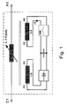
- FIG. 1 is the main winding with the inductance L shown with the terminals E1 and A1.
- the control winding L2 with the terminals E2 and A2 and the supply winding L3 with the terminals E3 and A3 are provided.
- the winding of the main winding L is supplied with an alternating current, whereby a voltage is provided to the inductively coupled supply winding ready, which is supplied to a rectifier.
- the rectified voltage is optionally smoothed with a capacitor and is then fed to a switching element 1, wherein this is operated clocked, for example, pulse width modulated.
- a switch encompassed by the switching element for example, a controllable power semiconductor switch is closed in each clock period for a first period and opened in a subsequent period.
- the current flowing through the control winding L2 current is controllable.
- the time average thus flows a direct current through the control coil L2, whereby thus the core of the main winding undergoes a corresponding magnetization. It is important that the magnetization of the core is not a linear function of the magnetic field generated by the current, but even changes to a saturation behavior for larger current values.
- the effective inductance L of the main winding is variable depending on the impressed in the control winding current.
- the control signals for the switching element 1 are contactless and even galvanically separated transferable.
- an optocoupler on the switching element 1 is provided for this purpose, which is in operative connection with a central control, not shown in the figure.
- the associated frequency is greater than the center frequency of the current fed into the primary conductor, that is, the current for the power supply Stromantells.
- the high-frequency current component can also be detected by means of the supply coil and can therefore be decoupled from the supply current component in the switching element.
- control signals only information can be transmitted in further exemplary embodiments according to the invention, wherein an electronic circuit for generating the control signals is then included in the switching element.
- ferrite materials As a material for the production of the core are suitable ferrite materials or other ferromagnetic or ferrimagnetic materials.
- the arrangement according to the invention can be used in a system for contactless energy transmission, in which an elongated laid primary conductor is provided, into which a melfelfrequenter current is impressed, in particular with a frequency between 10 and 500 kHz.
- the load which can be moved along the primary conductor has a secondary coil, which is inductively coupled to the primary conductor and to which such a capacitance is connected in series or in parallel, so that the associated resonant frequency substantially corresponds to the center frequency.
- the main winding of the arrangement according to the invention can be used as a secondary winding and the inductance can be changed by means of the current in the control winding, that is to say the resonance frequency can be regulated or tuned to the center frequency.
- a converter is used whose output stage is supplied from a unipolar voltage, the so-called intermediate circuit voltage, which is generated by a mains-fed rectifier.
- the output stage comprises half bridges, which each comprise two series-connected pulse-width-modulatedly controlled power semiconductor switches.
- a medium-frequency voltage can be generated, which is used to power a Gyratoranssen.
- a quadrupole which comprises at least one inductance and at least one capacitance, wherein the values of these variables are selected such that the associated resonant frequency substantially corresponds to the center frequency.
- an arrangement according to the invention can again be used as the inductance, so that the inductance can be tuned to the optimum value or subsequently regulated.
- aging, moisture, weather, temperature or otherwise caused deviations or drifts in the values can thus be compensated and / or readjusted.
- a transformer can be arranged, which is used to adjust the inductance. Also for its Induktlvltuschen the arrangement of the invention can be used to run this tunable.
- the elongated laid primary conductor is connected in total a capacity in series, so that the associated resonant frequency is tuned to the center frequency.
- an inductance can also be assigned to the tuning, for example in series, whereby this can be implemented as an arrangement according to the invention and thus a tuning to the resonant frequency is made possible.
- the components mentioned can therefore be equipped with inductors controllable according to the invention and thus tunable to the desired setpoint values.
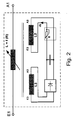
- a controllable resistor R is provided which thus determines the value of the main inductance. The way it works is the FIG. 1 executed accordingly.
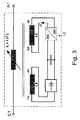
- FIG. 3 is instead of the controllable switching element 1 of FIG. 1 a controllable DC / DC converter provided.
- the way it works is the FIG. 1 executed accordingly.
- the duty cycle or the duty cycle ⁇ thus determine the inductance.
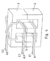
- the main winding L is wound around the first E-shaped core 2 and has the terminals E1 and A1.
- the second E-shaped core provided for closing the magnetic flux issuing from the first E-shaped core has the supply winding L3 about its center leg, the terminals being denoted by E3 and A3.
- the control winding L2 is embodied in two partial windings, wherein the first part winding is provided in the right main leg and the second part winding in the left main leg.
- the winding sense of the two partial windings are designed in opposite directions.
- the flux generated by the main winding L transits from the main leg of the first E-shaped core 2 into the main leg of the second E-shaped core 3 and then divides into two halves, the first in the first main leg and the second half in the second main leg flows.
- the field generated by the first partial winding of the control winding L2 in the first main leg is added to the flux component generated by the main winding and the field generated by the second partial winding of the control winding L2 is subtracted in the second main leg to the flux component generated by the main winding.
- a control of the inductance for the positive half-wave of the provided in the main winding L alternating current in the same manner as for the negative half-wave executable.
- the winding of the control winding is designed such that after a first turn of the first partial winding, the first turn of the second partial winding is carried out with the winding sense described above. Thereafter, a turn of the first partial winding is again carried out and continued by further alternating the execution of a turn of the respective partial winding.
- the E-shaped cores are rotationally symmetrical about their center leg around and thus have the in the FIG. 4 shown E-shaped cross section.
- the center leg includes a gap, so an air gap.
- the main legs are designed without an air gap and thus the smallest possible control power necessary. In the main field lines generated by the control winding so no air gap is present and thus only a small control current necessary, so only a small control performance. Even the small stream has a big impact.
Landscapes
- Engineering & Computer Science (AREA)
- Power Engineering (AREA)
- Dc-Dc Converters (AREA)
- Coils Of Transformers For General Uses (AREA)
- Coils Or Transformers For Communication (AREA)
Applications Claiming Priority (2)
| Application Number | Priority Date | Filing Date | Title |
|---|---|---|---|
| DE200810024602 DE102008024602B4 (de) | 2008-05-21 | 2008-05-21 | Schaltungsanordnung und deren Verwendung |
| EP09749527.9A EP2281293B1 (fr) | 2008-05-21 | 2009-04-22 | Inductance et dispositif |
Related Parent Applications (3)
| Application Number | Title | Priority Date | Filing Date |
|---|---|---|---|
| EP09749527.9 Division | 2009-04-22 | ||
| EP09749527.9A Division EP2281293B1 (fr) | 2008-05-21 | 2009-04-22 | Inductance et dispositif |
| EP09749527.9A Division-Into EP2281293B1 (fr) | 2008-05-21 | 2009-04-22 | Inductance et dispositif |
Publications (3)
| Publication Number | Publication Date |
|---|---|
| EP2357657A2 true EP2357657A2 (fr) | 2011-08-17 |
| EP2357657A3 EP2357657A3 (fr) | 2014-09-24 |
| EP2357657B1 EP2357657B1 (fr) | 2015-11-11 |
Family
ID=40849233
Family Applications (2)
| Application Number | Title | Priority Date | Filing Date |
|---|---|---|---|
| EP09749527.9A Active EP2281293B1 (fr) | 2008-05-21 | 2009-04-22 | Inductance et dispositif |
| EP11001711.8A Active EP2357657B1 (fr) | 2008-05-21 | 2009-04-22 | Agencement inductif |
Family Applications Before (1)
| Application Number | Title | Priority Date | Filing Date |
|---|---|---|---|
| EP09749527.9A Active EP2281293B1 (fr) | 2008-05-21 | 2009-04-22 | Inductance et dispositif |
Country Status (4)
| Country | Link |
|---|---|
| EP (2) | EP2281293B1 (fr) |
| CN (1) | CN102037525B (fr) |
| DE (1) | DE102008064640B4 (fr) |
| WO (1) | WO2009141037A1 (fr) |
Families Citing this family (6)
| Publication number | Priority date | Publication date | Assignee | Title |
|---|---|---|---|---|
| EP3076411B1 (fr) * | 2015-04-01 | 2017-11-29 | Siemens Aktiengesellschaft | Circuit de reduction d'une part de flux continu magnetique dans le noyau d'un transformateur |
| CN106411115B (zh) * | 2016-11-21 | 2019-03-08 | 盐城工学院 | 一种可变电感工作范围连续扩展的方法 |
| JP6786453B2 (ja) * | 2017-08-04 | 2020-11-18 | 矢崎総業株式会社 | サージ電圧低減部材 |
| AT520274B1 (de) * | 2017-08-08 | 2023-09-15 | Himmelstoss Dipl Ing Dr Felix | DC/DC Konverter mit zusätzlichem induktiv gekoppeltem spannungsbidirektionalen Schalter zur Überbrückung einer Induktivität |
| WO2019076483A1 (fr) * | 2017-10-18 | 2019-04-25 | Sew-Eurodrive Gmbh & Co. Kg | Chargeur et système de transmission d'énergie vers une unité mobile ayant un accumulateur d'énergie et un enroulement secondaire |
| DE102021205817A1 (de) | 2021-06-09 | 2022-12-15 | Siemens Aktiengesellschaft | Ladestation für ein elektrisch antreibbares Fahrzeug |
Family Cites Families (14)
| Publication number | Priority date | Publication date | Assignee | Title |
|---|---|---|---|---|
| US2673321A (en) * | 1948-11-17 | 1954-03-23 | Westinghouse Air Brake Co | Transformer voltage regulating arrangement |
| US3634534A (en) * | 1969-08-22 | 1972-01-11 | Chevron Res | Separation of chemicals using fractionation and heterogeneous catalysis |
| US3631534A (en) | 1969-09-05 | 1971-12-28 | Matsushita Electric Industrial Co Ltd | Variable inductance device |
| US4213084A (en) | 1977-05-20 | 1980-07-15 | Tdk Electronics Company Limited | Variable leakage transformer |
| CA1229381A (fr) * | 1985-01-16 | 1987-11-17 | Leonard Bolduc | Inductance variable autocontrolee a entrefers |
| EP0443342A1 (fr) | 1990-02-23 | 1991-08-28 | Bonnet, André | Procédé de contrôle du transfert d'énergie dans un convertisseur statique; convertisseur statique d'énergie pour sa mise en oeuvre et alimentation électrique utilisant un tel convertisseur |
| US5319343A (en) * | 1990-08-21 | 1994-06-07 | Powercube Corporation | Integrated magnetic inductor having series and common mode windings |
| US5424691A (en) * | 1994-02-03 | 1995-06-13 | Sadinsky; Samuel | Apparatus and method for electronically controlled admittance matching network |
| US6317021B1 (en) * | 1998-05-18 | 2001-11-13 | Nmb (Usa) Inc. | Variable inductor |
| DE10053373B4 (de) | 2000-10-27 | 2019-10-02 | Sew-Eurodrive Gmbh & Co Kg | Verfahren und Vorrichtung zur berührungslosen Energieübertragung |
| DE10141884B4 (de) | 2000-11-15 | 2020-06-04 | Abb Schweiz Ag | Einspeiseschaltung eines ein Magnetfeld erzeugenden Resonanzkreises sowie Steuer/Regeleinrichtung hierzu |
| DE10339340B4 (de) | 2003-08-25 | 2020-02-20 | Sew-Eurodrive Gmbh & Co Kg | Vorrichtung zur berührungslosen Energieübertragung |
| JP4266951B2 (ja) * | 2005-03-31 | 2009-05-27 | Tdk株式会社 | 磁気素子および電源装置 |
| DE102006043960B4 (de) * | 2006-09-14 | 2021-01-21 | Sew-Eurodrive Gmbh & Co Kg | System zur berührungslosen Energieübertragung |
-
2008
- 2008-05-21 DE DE102008064640.7A patent/DE102008064640B4/de active Active
-
2009
- 2009-04-22 WO PCT/EP2009/002920 patent/WO2009141037A1/fr not_active Ceased
- 2009-04-22 CN CN200980118175.XA patent/CN102037525B/zh active Active
- 2009-04-22 EP EP09749527.9A patent/EP2281293B1/fr active Active
- 2009-04-22 EP EP11001711.8A patent/EP2357657B1/fr active Active
Non-Patent Citations (1)
| Title |
|---|
| None |
Also Published As
| Publication number | Publication date |
|---|---|
| EP2357657A3 (fr) | 2014-09-24 |
| WO2009141037A1 (fr) | 2009-11-26 |
| DE102008064640B4 (de) | 2024-08-22 |
| DE102008064640A1 (de) | 2009-12-03 |
| CN102037525A (zh) | 2011-04-27 |
| CN102037525B (zh) | 2014-01-15 |
| EP2281293A1 (fr) | 2011-02-09 |
| EP2281293B1 (fr) | 2017-02-01 |
| EP2357657B1 (fr) | 2015-11-11 |
Similar Documents
| Publication | Publication Date | Title |
|---|---|---|
| DE112016006342B4 (de) | Stromwandler und kontaktloses Leistungsversorgungssystem | |
| EP2281293B1 (fr) | Inductance et dispositif | |
| DE10122534A1 (de) | Resonanter Konverter | |
| EP2999079B1 (fr) | Systeme et procede de fonctionnement d'un systeme destine a la transmission d'energie inductive vers un consommateur electrique | |
| DE4431050A1 (de) | Gleichspannungswandler | |
| DE102008024602B4 (de) | Schaltungsanordnung und deren Verwendung | |
| WO2009074207A2 (fr) | Système de transfert d'énergie sans contact et procédé correspondant | |
| EP2605361B1 (fr) | Agencement et procédé de fonctionnement d'un agencement destinés à la transmission d'énergie inductive vers un consommateur électrique | |
| DE102010063112A1 (de) | Vorrichtung zum induktiven Heizen eines Kraftstoffeinspritzventils | |
| DE102018203391A1 (de) | System zur induktiven Energieübertragung von einer ersten Energiequelle an eine Last und Verfahren zum Verstellen einer Resonanzfrequenz eines elektrischen Schwingkreises | |
| WO2022258278A1 (fr) | Borne de recharge pour un véhicule pouvant être entraîné électriquement | |
| EP3462590A1 (fr) | Hacheur résonant | |
| EP0797223B1 (fr) | Composant inductive à comportement magnétique accordable | |
| DE102010006598B4 (de) | Verfahren zum Betreiben einer Leitungsabschlusseinrichtung und Leitungsabschlusseinrichtung | |
| DE102022002735A1 (de) | Anlage zur berührungslosen Energieübertragung von einem Primärleiter zu einer Sekundärspule | |
| WO2025119664A1 (fr) | Dispositif de circuit pour compensation de puissance réactive dans un appareil de charge inductive, appareil de charge inductive et système de transmission d'énergie inductive | |
| WO2016082901A1 (fr) | Procédé et système d'exploitation d'une station de charge pour la transmission inductive d'énergie électrique à un véhicule avec accumulateur d'énergie | |
| EP4399791A1 (fr) | Convertisseur et procédé pour amener un rapport de transformation réel en ligne avec un rapport de transformation cible | |
| DE19608819A1 (de) | Elektrische Versorgungs-Schaltung für Lampen | |
| DE2225720A1 (de) | Elektrisches Gerat |
Legal Events
| Date | Code | Title | Description |
|---|---|---|---|
| PUAI | Public reference made under article 153(3) epc to a published international application that has entered the european phase |
Free format text: ORIGINAL CODE: 0009012 |
|
| 17P | Request for examination filed |
Effective date: 20110302 |
|
| AC | Divisional application: reference to earlier application |
Ref document number: 2281293 Country of ref document: EP Kind code of ref document: P |
|
| AK | Designated contracting states |
Kind code of ref document: A2 Designated state(s): AT BE BG CH CY CZ DE DK EE ES FI FR GB GR HR HU IE IS IT LI LT LU LV MC MK MT NL NO PL PT RO SE SI SK TR |
|
| PUAL | Search report despatched |
Free format text: ORIGINAL CODE: 0009013 |
|
| AK | Designated contracting states |
Kind code of ref document: A3 Designated state(s): AT BE BG CH CY CZ DE DK EE ES FI FR GB GR HR HU IE IS IT LI LT LU LV MC MK MT NL NO PL PT RO SE SI SK TR |
|
| RIC1 | Information provided on ipc code assigned before grant |
Ipc: H01F 29/14 20060101ALI20140819BHEP Ipc: H01F 27/42 20060101ALI20140819BHEP Ipc: H01F 27/00 20060101AFI20140819BHEP Ipc: H01F 21/08 20060101ALI20140819BHEP Ipc: H01F 38/14 20060101ALI20140819BHEP Ipc: H01F 3/14 20060101ALI20140819BHEP |
|
| 17Q | First examination report despatched |
Effective date: 20140923 |
|
| RBV | Designated contracting states (corrected) |
Designated state(s): AT BE BG CH CY CZ DE DK EE ES FI FR GB GR HR HU IE IS IT LI LT LU LV MC MK MT NL NO PL PT RO SE SI SK TR |
|
| GRAP | Despatch of communication of intention to grant a patent |
Free format text: ORIGINAL CODE: EPIDOSNIGR1 |
|
| INTG | Intention to grant announced |
Effective date: 20150701 |
|
| GRAS | Grant fee paid |
Free format text: ORIGINAL CODE: EPIDOSNIGR3 |
|
| GRAA | (expected) grant |
Free format text: ORIGINAL CODE: 0009210 |
|
| AC | Divisional application: reference to earlier application |
Ref document number: 2281293 Country of ref document: EP Kind code of ref document: P |
|
| AK | Designated contracting states |
Kind code of ref document: B1 Designated state(s): AT BE BG CH CY CZ DE DK EE ES FI FR GB GR HR HU IE IS IT LI LT LU LV MC MK MT NL NO PL PT RO SE SI SK TR |
|
| REG | Reference to a national code |
Ref country code: GB Ref legal event code: FG4D Free format text: NOT ENGLISH |
|
| REG | Reference to a national code |
Ref country code: CH Ref legal event code: EP |
|
| REG | Reference to a national code |
Ref country code: IE Ref legal event code: FG4D Free format text: LANGUAGE OF EP DOCUMENT: GERMAN |
|
| REG | Reference to a national code |
Ref country code: AT Ref legal event code: REF Ref document number: 760819 Country of ref document: AT Kind code of ref document: T Effective date: 20151215 |
|
| REG | Reference to a national code |
Ref country code: DE Ref legal event code: R096 Ref document number: 502009011850 Country of ref document: DE |
|
| REG | Reference to a national code |
Ref country code: FR Ref legal event code: PLFP Year of fee payment: 8 |
|
| REG | Reference to a national code |
Ref country code: LT Ref legal event code: MG4D |
|
| REG | Reference to a national code |
Ref country code: NL Ref legal event code: MP Effective date: 20160211 |
|
| PG25 | Lapsed in a contracting state [announced via postgrant information from national office to epo] |
Ref country code: NO Free format text: LAPSE BECAUSE OF FAILURE TO SUBMIT A TRANSLATION OF THE DESCRIPTION OR TO PAY THE FEE WITHIN THE PRESCRIBED TIME-LIMIT Effective date: 20160211 Ref country code: ES Free format text: LAPSE BECAUSE OF FAILURE TO SUBMIT A TRANSLATION OF THE DESCRIPTION OR TO PAY THE FEE WITHIN THE PRESCRIBED TIME-LIMIT Effective date: 20151111 Ref country code: HR Free format text: LAPSE BECAUSE OF FAILURE TO SUBMIT A TRANSLATION OF THE DESCRIPTION OR TO PAY THE FEE WITHIN THE PRESCRIBED TIME-LIMIT Effective date: 20151111 Ref country code: LT Free format text: LAPSE BECAUSE OF FAILURE TO SUBMIT A TRANSLATION OF THE DESCRIPTION OR TO PAY THE FEE WITHIN THE PRESCRIBED TIME-LIMIT Effective date: 20151111 Ref country code: IS Free format text: LAPSE BECAUSE OF FAILURE TO SUBMIT A TRANSLATION OF THE DESCRIPTION OR TO PAY THE FEE WITHIN THE PRESCRIBED TIME-LIMIT Effective date: 20160311 Ref country code: IT Free format text: LAPSE BECAUSE OF FAILURE TO SUBMIT A TRANSLATION OF THE DESCRIPTION OR TO PAY THE FEE WITHIN THE PRESCRIBED TIME-LIMIT Effective date: 20151111 Ref country code: NL Free format text: LAPSE BECAUSE OF FAILURE TO SUBMIT A TRANSLATION OF THE DESCRIPTION OR TO PAY THE FEE WITHIN THE PRESCRIBED TIME-LIMIT Effective date: 20151111 |
|
| PG25 | Lapsed in a contracting state [announced via postgrant information from national office to epo] |
Ref country code: PL Free format text: LAPSE BECAUSE OF FAILURE TO SUBMIT A TRANSLATION OF THE DESCRIPTION OR TO PAY THE FEE WITHIN THE PRESCRIBED TIME-LIMIT Effective date: 20151111 Ref country code: PT Free format text: LAPSE BECAUSE OF FAILURE TO SUBMIT A TRANSLATION OF THE DESCRIPTION OR TO PAY THE FEE WITHIN THE PRESCRIBED TIME-LIMIT Effective date: 20160311 Ref country code: GR Free format text: LAPSE BECAUSE OF FAILURE TO SUBMIT A TRANSLATION OF THE DESCRIPTION OR TO PAY THE FEE WITHIN THE PRESCRIBED TIME-LIMIT Effective date: 20160212 Ref country code: FI Free format text: LAPSE BECAUSE OF FAILURE TO SUBMIT A TRANSLATION OF THE DESCRIPTION OR TO PAY THE FEE WITHIN THE PRESCRIBED TIME-LIMIT Effective date: 20151111 Ref country code: SE Free format text: LAPSE BECAUSE OF FAILURE TO SUBMIT A TRANSLATION OF THE DESCRIPTION OR TO PAY THE FEE WITHIN THE PRESCRIBED TIME-LIMIT Effective date: 20151111 Ref country code: LV Free format text: LAPSE BECAUSE OF FAILURE TO SUBMIT A TRANSLATION OF THE DESCRIPTION OR TO PAY THE FEE WITHIN THE PRESCRIBED TIME-LIMIT Effective date: 20151111 |
|
| PG25 | Lapsed in a contracting state [announced via postgrant information from national office to epo] |
Ref country code: CZ Free format text: LAPSE BECAUSE OF FAILURE TO SUBMIT A TRANSLATION OF THE DESCRIPTION OR TO PAY THE FEE WITHIN THE PRESCRIBED TIME-LIMIT Effective date: 20151111 |
|
| REG | Reference to a national code |
Ref country code: DE Ref legal event code: R097 Ref document number: 502009011850 Country of ref document: DE |
|
| PG25 | Lapsed in a contracting state [announced via postgrant information from national office to epo] |
Ref country code: BE Free format text: LAPSE BECAUSE OF NON-PAYMENT OF DUE FEES Effective date: 20160430 Ref country code: EE Free format text: LAPSE BECAUSE OF FAILURE TO SUBMIT A TRANSLATION OF THE DESCRIPTION OR TO PAY THE FEE WITHIN THE PRESCRIBED TIME-LIMIT Effective date: 20151111 Ref country code: DK Free format text: LAPSE BECAUSE OF FAILURE TO SUBMIT A TRANSLATION OF THE DESCRIPTION OR TO PAY THE FEE WITHIN THE PRESCRIBED TIME-LIMIT Effective date: 20151111 Ref country code: SK Free format text: LAPSE BECAUSE OF FAILURE TO SUBMIT A TRANSLATION OF THE DESCRIPTION OR TO PAY THE FEE WITHIN THE PRESCRIBED TIME-LIMIT Effective date: 20151111 Ref country code: RO Free format text: LAPSE BECAUSE OF FAILURE TO SUBMIT A TRANSLATION OF THE DESCRIPTION OR TO PAY THE FEE WITHIN THE PRESCRIBED TIME-LIMIT Effective date: 20151111 |
|
| PLBE | No opposition filed within time limit |
Free format text: ORIGINAL CODE: 0009261 |
|
| STAA | Information on the status of an ep patent application or granted ep patent |
Free format text: STATUS: NO OPPOSITION FILED WITHIN TIME LIMIT |
|
| 26N | No opposition filed |
Effective date: 20160812 |
|
| PG25 | Lapsed in a contracting state [announced via postgrant information from national office to epo] |
Ref country code: SI Free format text: LAPSE BECAUSE OF FAILURE TO SUBMIT A TRANSLATION OF THE DESCRIPTION OR TO PAY THE FEE WITHIN THE PRESCRIBED TIME-LIMIT Effective date: 20151111 |
|
| REG | Reference to a national code |
Ref country code: CH Ref legal event code: PL |
|
| PG25 | Lapsed in a contracting state [announced via postgrant information from national office to epo] |
Ref country code: LU Free format text: LAPSE BECAUSE OF FAILURE TO SUBMIT A TRANSLATION OF THE DESCRIPTION OR TO PAY THE FEE WITHIN THE PRESCRIBED TIME-LIMIT Effective date: 20160422 |
|
| REG | Reference to a national code |
Ref country code: IE Ref legal event code: MM4A |
|
| PG25 | Lapsed in a contracting state [announced via postgrant information from national office to epo] |
Ref country code: CH Free format text: LAPSE BECAUSE OF NON-PAYMENT OF DUE FEES Effective date: 20160430 Ref country code: LI Free format text: LAPSE BECAUSE OF NON-PAYMENT OF DUE FEES Effective date: 20160430 |
|
| REG | Reference to a national code |
Ref country code: FR Ref legal event code: PLFP Year of fee payment: 9 |
|
| PG25 | Lapsed in a contracting state [announced via postgrant information from national office to epo] |
Ref country code: IE Free format text: LAPSE BECAUSE OF NON-PAYMENT OF DUE FEES Effective date: 20160422 |
|
| REG | Reference to a national code |
Ref country code: AT Ref legal event code: MM01 Ref document number: 760819 Country of ref document: AT Kind code of ref document: T Effective date: 20160422 |
|
| PG25 | Lapsed in a contracting state [announced via postgrant information from national office to epo] |
Ref country code: AT Free format text: LAPSE BECAUSE OF NON-PAYMENT OF DUE FEES Effective date: 20160422 |
|
| REG | Reference to a national code |
Ref country code: FR Ref legal event code: PLFP Year of fee payment: 10 |
|
| PG25 | Lapsed in a contracting state [announced via postgrant information from national office to epo] |
Ref country code: HU Free format text: LAPSE BECAUSE OF FAILURE TO SUBMIT A TRANSLATION OF THE DESCRIPTION OR TO PAY THE FEE WITHIN THE PRESCRIBED TIME-LIMIT; INVALID AB INITIO Effective date: 20090422 Ref country code: CY Free format text: LAPSE BECAUSE OF FAILURE TO SUBMIT A TRANSLATION OF THE DESCRIPTION OR TO PAY THE FEE WITHIN THE PRESCRIBED TIME-LIMIT Effective date: 20151111 |
|
| PG25 | Lapsed in a contracting state [announced via postgrant information from national office to epo] |
Ref country code: MC Free format text: LAPSE BECAUSE OF FAILURE TO SUBMIT A TRANSLATION OF THE DESCRIPTION OR TO PAY THE FEE WITHIN THE PRESCRIBED TIME-LIMIT Effective date: 20151111 Ref country code: MT Free format text: LAPSE BECAUSE OF FAILURE TO SUBMIT A TRANSLATION OF THE DESCRIPTION OR TO PAY THE FEE WITHIN THE PRESCRIBED TIME-LIMIT Effective date: 20151111 Ref country code: TR Free format text: LAPSE BECAUSE OF FAILURE TO SUBMIT A TRANSLATION OF THE DESCRIPTION OR TO PAY THE FEE WITHIN THE PRESCRIBED TIME-LIMIT Effective date: 20151111 Ref country code: MK Free format text: LAPSE BECAUSE OF FAILURE TO SUBMIT A TRANSLATION OF THE DESCRIPTION OR TO PAY THE FEE WITHIN THE PRESCRIBED TIME-LIMIT Effective date: 20151111 |
|
| PG25 | Lapsed in a contracting state [announced via postgrant information from national office to epo] |
Ref country code: BG Free format text: LAPSE BECAUSE OF FAILURE TO SUBMIT A TRANSLATION OF THE DESCRIPTION OR TO PAY THE FEE WITHIN THE PRESCRIBED TIME-LIMIT Effective date: 20151111 |
|
| PGFP | Annual fee paid to national office [announced via postgrant information from national office to epo] |
Ref country code: DE Payment date: 20250430 Year of fee payment: 17 |
|
| REG | Reference to a national code |
Ref country code: DE Ref legal event code: R084 Ref document number: 502009011850 Country of ref document: DE |
|
| PGFP | Annual fee paid to national office [announced via postgrant information from national office to epo] |
Ref country code: GB Payment date: 20260312 Year of fee payment: 18 |
|
| PGFP | Annual fee paid to national office [announced via postgrant information from national office to epo] |
Ref country code: FR Payment date: 20260309 Year of fee payment: 18 |