EP2357793A1 - Procédé et appareil pour le contrôle de l'auto-focus d'un appareil photo numérique - Google Patents
Procédé et appareil pour le contrôle de l'auto-focus d'un appareil photo numérique Download PDFInfo
- Publication number
- EP2357793A1 EP2357793A1 EP10195833A EP10195833A EP2357793A1 EP 2357793 A1 EP2357793 A1 EP 2357793A1 EP 10195833 A EP10195833 A EP 10195833A EP 10195833 A EP10195833 A EP 10195833A EP 2357793 A1 EP2357793 A1 EP 2357793A1
- Authority
- EP
- European Patent Office
- Prior art keywords
- focus lens
- function
- preset
- maximum value
- calculated
- Prior art date
- Legal status (The legal status is an assumption and is not a legal conclusion. Google has not performed a legal analysis and makes no representation as to the accuracy of the status listed.)
- Granted
Links
Images



Classifications
-
- H—ELECTRICITY
- H04—ELECTRIC COMMUNICATION TECHNIQUE
- H04N—PICTORIAL COMMUNICATION, e.g. TELEVISION
- H04N23/00—Cameras or camera modules comprising electronic image sensors; Control thereof
- H04N23/60—Control of cameras or camera modules
- H04N23/67—Focus control based on electronic image sensor signals
-
- H—ELECTRICITY
- H04—ELECTRIC COMMUNICATION TECHNIQUE
- H04N—PICTORIAL COMMUNICATION, e.g. TELEVISION
- H04N23/00—Cameras or camera modules comprising electronic image sensors; Control thereof
- H04N23/60—Control of cameras or camera modules
- H04N23/67—Focus control based on electronic image sensor signals
- H04N23/673—Focus control based on electronic image sensor signals based on contrast or high frequency components of image signals, e.g. hill climbing method
-
- G—PHYSICS
- G02—OPTICS
- G02B—OPTICAL ELEMENTS, SYSTEMS OR APPARATUS
- G02B7/00—Mountings, adjusting means, or light-tight connections, for optical elements
- G02B7/28—Systems for automatic generation of focusing signals
- G02B7/36—Systems for automatic generation of focusing signals using image sharpness techniques, e.g. image processing techniques for generating autofocus signals
- G02B7/38—Systems for automatic generation of focusing signals using image sharpness techniques, e.g. image processing techniques for generating autofocus signals measured at different points on the optical axis, e.g. focussing on two or more planes and comparing image data
-
- G—PHYSICS
- G03—PHOTOGRAPHY; CINEMATOGRAPHY; ANALOGOUS TECHNIQUES USING WAVES OTHER THAN OPTICAL WAVES; ELECTROGRAPHY; HOLOGRAPHY
- G03B—APPARATUS OR ARRANGEMENTS FOR TAKING PHOTOGRAPHS OR FOR PROJECTING OR VIEWING THEM; APPARATUS OR ARRANGEMENTS EMPLOYING ANALOGOUS TECHNIQUES USING WAVES OTHER THAN OPTICAL WAVES; ACCESSORIES THEREFOR
- G03B13/00—Viewfinders; Focusing aids for cameras; Means for focusing for cameras; Autofocus systems for cameras
- G03B13/32—Means for focusing
- G03B13/34—Power focusing
- G03B13/36—Autofocus systems
-
- G—PHYSICS
- G03—PHOTOGRAPHY; CINEMATOGRAPHY; ANALOGOUS TECHNIQUES USING WAVES OTHER THAN OPTICAL WAVES; ELECTROGRAPHY; HOLOGRAPHY
- G03B—APPARATUS OR ARRANGEMENTS FOR TAKING PHOTOGRAPHS OR FOR PROJECTING OR VIEWING THEM; APPARATUS OR ARRANGEMENTS EMPLOYING ANALOGOUS TECHNIQUES USING WAVES OTHER THAN OPTICAL WAVES; ACCESSORIES THEREFOR
- G03B3/00—Focusing arrangements of general interest for cameras, projectors or printers
- G03B3/10—Power-operated focusing
-
- H—ELECTRICITY
- H04—ELECTRIC COMMUNICATION TECHNIQUE
- H04N—PICTORIAL COMMUNICATION, e.g. TELEVISION
- H04N23/00—Cameras or camera modules comprising electronic image sensors; Control thereof
- H04N23/60—Control of cameras or camera modules
- H04N23/63—Control of cameras or camera modules by using electronic viewfinders
- H04N23/631—Graphical user interfaces [GUI] specially adapted for controlling image capture or setting capture parameters
Definitions
- the present invention relates generally to a digital camera, and more particularly, to a method and apparatus for auto-focus control of a digital camera.
- digital cameras in general, and in particular high-pixel digital cameras installed in mobile devices, such as cellular phones, have an auto-focus function for automatically focusing the lens when taking a photograph.
- phase-difference detection scheme typically employed in Digital Single Lens Reflex (DSLR) cameras
- contrast detection scheme typically employed in compact digital cameras and cellular phone cameras.
- the phase-difference detection scheme distributes light, which has passed through a lens, between a viewfinder and an auto-focus (AF) sensor through a mirror, to separate light which is incident on the AF sensor in two directions on a focus surface, to detect both beams of light by means of a line sensor, and to determine if the camera is focusing on a foreground or a background.
- AF auto-focus
- Such a phase-difference detection scheme requires a lens system and a separate sensor for auto-focusing.
- the contrast detection scheme is based on a hill climbing method for finding a position at which an edge value is a maximum while moving a focus lens in given steps within an entire movable range of the focus lens or a part of the movable range.
- FIG. 1 schematically illustrates the operation of an auto-focus control method using a normal contrast detection scheme.
- the contrast detection scheme is implemented in such a manner as to trace a change in an edge value, which is obtained by filtering an electrical signal given from an image sensor, according to each position while moving a focus lens at the same intervals, and to move the focus lens to a focus position where the highest focus value is obtained according to a result of the tracing, as shown in FIG. 1B .
- the present invention has been made to solve the above-mentioned problems occurring in the prior art, and the present invention provides an auto-focus control method and apparatus for rapidly achieving an auto-focus control in a digital camera.
- a method for auto-focus control of a digital camera including moving a focus lens of the digital camera to a position for a longest-distance photographing, and then extracting an edge value according to a corresponding position while moving the focus lens by a preset interval in a direction toward an image sensor; estimating a form of a preset function based on the extracted edge values, and calculating a maximum value of the estimated function; calculating a difference between a maximum value of the preset function calculated at a first current position of the focus lens and a maximum value of the preset function calculated at a previous position of the focus lens; and moving the focus lens to a position corresponding to a currently-calculated maximum value of the preset function when the difference between the maximum value of the preset function calculated at the first current position of the focus lens and the maximum value of the preset function calculated at the previous position of the focus lens is less than or equal to a preset threshold value.
- an apparatus for auto-focus control of a digital camera including a lens unit configured with a zoom lens and a focus lens which is movable along an optical axis in order to focus an optical image formed on an image sensor, the lens unit allowing an optical image of a subject to be formed on the image sensor; an image sensor unit for converting image information of the subject into an electrical signal; an image signal processor (ISP) for extracting an edge value from the electrical signal, into which the image information has been converted; a driving unit for physically moving the lens unit according to a control signal received from a controller; and the controller for controlling the driving unit to move the focus lens of the digital camera to a position for a longest-distance photographing, extracting an edge value according to a corresponding position while moving the focus lens by a preset interval in a direction toward the image sensor, estimating a form of a preset function based on the extracted edge values, calculating a maximum value of the estimated function, calculating a difference
- the present invention provides a method and apparatus for achieving rapidly an auto-focus control in a digital camera, which will be described in detail with reference to the accompanying drawings.
- FIG. 2 is a block diagram illustrating the configuration of an auto-focus control apparatus according to an embodiment of the present invention.
- the auto-focus control apparatus includes a lens unit 110, an image sensor unit 120, an image signal processor (ISP) 130, a controller 140, a display unit 150, a driving unit 170, and an input unit 160.
- ISP image signal processor
- the lens unit 110 forms an optical image of a subject on the image sensor unit 120.
- the lens unit 110 includes a zoom lens (not shown), and a focus lens (not shown) which is movable along an optical axis in order to focus the optical image formed on the image sensor unit. Through the lens unit 110, a digital image of a subject desired to be photographed by the user is obtained.
- the image sensor unit 120 may include a complementary metal-oxide semiconductor (CMOS), a charge-coupled device (CCD), etc.
- CMOS complementary metal-oxide semiconductor
- CCD charge-coupled device
- the image sensor unit 120 is implemented in a form where a plurality of photo-detectors are integrated as the respective pixels, and converts image information of a subject into an electrical signal and then transfers the electrical data to the ISP 130.
- the ISP 130 processes an image signal, which has been input from the image sensor unit 120, in units of frames. Also, according to an embodiment of the present invention, the ISP 130 extracts an edge value from the electrical signal, into which the image information has been converted.
- the display unit 150 displays an image photographed according to the control of the controller 140.
- the input unit 160 receives and transfers the user's input to the controller 140.
- the display unit 150 When the display unit 150 is implemented with a touch screen, the display unit 150 can operate as an input unit.
- the controller 140 controls the respective components of the digital camera.
- the controller 140 estimates a position having the maximum edge value from given edge value information, and outputs a control signal to the driving unit 170 to move the lens system to the estimated position.
- the controller 140 extracts edge values through the ISP 130 according to each corresponding position while moving the focus lens by a preset interval, estimates a function having the form of an inverse function of a quadratic polynomial function based on the extracted edge values, and calculates the maximum value of the estimated function.
- the controller 140 moves the focus lens by the preset interval, extracts an edge value according to a corresponding position, again estimates a form of a function through the use of data, which contains the edge value extracted according to the current position of the focus lens, and the previously-extracted edge values, and calculates a difference between the maximum value of the quadratic polynomial function's inverse function calculated/estimated at the current position of the focus lens, and the maximum value of the quadratic polynomial function's inverse function calculated/estimated at a previous position of the focus lens.
- the controller 140 controls the driving unit 170 to move the focus lens to the current position having the maximum value of the quadratic polynomial function's inverse function which is currently calculated/estimated.
- the driving unit 170 physically moves the lens unit 110 according to a control signal received from the controller 140.
- the digital camera may further include a buffer (not shown) for temporarily storing an image obtained through a photographing process.
- FIG. 3 is a flowchart illustrating the flow of the auto-focus control operation according to an embodiment of the present invention.
- the controller 140 controls the driving unit 170 to move a focus lens to a position for the longest-distance photographing, and measures edge value data of corresponding positions while moving the focus lens by the preset interval from a corresponding position in a direction toward the image sensor 120 in step 610.
- an edge value is extracted at each position.
- an estimation model having the form of the quadratic polynomial function's inverse function is calculated through the use of the measured edge value data, and a peak value, that represents a position having the maximum value of the estimated function, is detected.
- a peak value that represents a position having the maximum value of the estimated function.
- the calculation of the estimation model is performed in such a manner as to perform a fitting to a preset function through the use of an inverse matrix, and to calculate a position having the maximum value from a coefficient value of the fitted function.
- An estimation model having the form of the quadratic polynomial function's inverse function may be expressed as Equation (1) below.
- Equation (1) 1 ax 2 + bx + c
- Equation (1) "a, b, c" represents the coefficient of quadratic polynomial function.
- an operation is performed in a least square method using a pseudo-inverse matrix.
- a function for each edge value may be expressed as Equation (2) below.
- Equation (3) may be simplified to Equation (4) below.
- Equation (3) When Equation (3) is expressed as Equation (4), a coefficient value for an estimation model is obtained from a pseudo-inverse matrix of A, as shown in Equation (5). In this case, a position having a peak value becomes "-b/2a,” as shown in Equation (6) below.
- x peak - b 2 ⁇ a
- FIG. 4 is a graph illustrating an example of an estimation model of the quadratic polynomial function's inverse function obtained from sample data in the auto-focus control method according to an embodiment of the present invention.
- the estimation model as shown in FIG. 4 may be calculated through the use of edge value data.
- an edge value is measured after the lens moves by a preset next interval, and a new fitted estimation model is calculated through the use of edge value data including the measured edge value.
- a new fitted estimation model is calculated through the use of edge value data including the measured edge value.
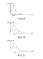
- FIG. 5A is a graph illustrating an estimation model which is estimated with three pieces of edge value data when the focus lens moves three times
- FIG. 5B is a graph illustrating an estimation model which is estimated with four pieces of edge value data when the focus lens moves four times
- FIG. 5A is a graph illustrating an estimation model which is estimated with five pieces of edge value data when the focus lens moves five times.
- step 640 it is determined if the difference between the peak value though the estimation model calculated at the previous position of the lens and the peak value though the estimation model calculated at the current position of the lens is less than or equal to a preset threshold value.
- FIGS. 5A to 5C illustrate estimation models calculated whenever the number of pieces of sample data increases in the auto-focus control method.
- FIG. 6 is a graph illustrating peak values obtained through estimation models according to the positions (steps) of the focus lens. According to an embodiment of the present invention, when a difference between a current peak value and a previous peak value is less than or equal to a preset threshold value ⁇ x th , the current position corresponding to the current peak value is determined to be a focused position. That is, referring to FIG.
- a difference between the peak value of a fourth position and the peak value of a third position, which is a previous peak value, is less than the preset threshold value, so that the focus lens is moved and stopped at the position at which the fourth peak value has been detected.
- step 640 when the difference between the peak value though the estimation model calculated at the previous position of the lens and the peak value though the estimation model calculated at the current position of the lens is greater than the preset threshold value, the procedure proceeds to step 650.
- step 650 the focus lens moves by a preset interval, and the process returns to steps 620 and 630 in which a new estimation model is calculated, a peak value is obtained, and then the procedure returns to step 640.
- step 640 When the difference between the peak value through the estimation model calculated at the previous position of the lens and the peak value through the estimation model calculated at the current position of the lens is less than or equal to the preset threshold value as a result of step 640, the calculation for the estimation is terminated, the focus lens moves to an estimated position, photographing is performed, and then the procedure is terminated.
- Equation (7) "w” represents a weight, “y” represents an estimation model, and “i” represents a sampling order from one to n.
- Equation (7) is expressed in a matrix form as shown in Equation (8) below, and a peak value can be calculated through the use of a pseudo-inverse matrix as shown in Equation (9) below.
- Equations (8) and (9) represent coefficients of an estimation model of an inverse matrix of a quadratic polynomial function. In this case, a peak value can be calculated by Equation (6) as well.
- the movement of the lens for an auto-focus control is minimized in a digital camera, so that the user of the digital camera can rapidly take a desired photograph without missing a moment.
Landscapes
- Physics & Mathematics (AREA)
- General Physics & Mathematics (AREA)
- Engineering & Computer Science (AREA)
- Multimedia (AREA)
- Signal Processing (AREA)
- Computer Vision & Pattern Recognition (AREA)
- Optics & Photonics (AREA)
- Automatic Focus Adjustment (AREA)
- Studio Devices (AREA)
Applications Claiming Priority (1)
| Application Number | Priority Date | Filing Date | Title |
|---|---|---|---|
| KR1020100002854A KR101137615B1 (ko) | 2010-01-12 | 2010-01-12 | 디지털 카메라의 자동 초점 조정 방법 및 장치 |
Publications (2)
| Publication Number | Publication Date |
|---|---|
| EP2357793A1 true EP2357793A1 (fr) | 2011-08-17 |
| EP2357793B1 EP2357793B1 (fr) | 2013-03-13 |
Family
ID=43876997
Family Applications (1)
| Application Number | Title | Priority Date | Filing Date |
|---|---|---|---|
| EP10195833A Not-in-force EP2357793B1 (fr) | 2010-01-12 | 2010-12-20 | Procédé et appareil pour le contrôle de l'auto-focus d'un appareil photo numérique |
Country Status (4)
| Country | Link |
|---|---|
| US (1) | US8315512B2 (fr) |
| EP (1) | EP2357793B1 (fr) |
| KR (1) | KR101137615B1 (fr) |
| CN (1) | CN102131052B (fr) |
Families Citing this family (11)
| Publication number | Priority date | Publication date | Assignee | Title |
|---|---|---|---|---|
| JP5919436B2 (ja) * | 2013-06-06 | 2016-05-18 | 富士フイルム株式会社 | オート・フォーカス装置およびその動作制御方法 |
| CN103424851B (zh) * | 2013-08-22 | 2015-07-22 | 福建福光数码科技有限公司 | 高分辨率长焦距自动对焦、自动调光机载变焦距摄像镜头 |
| JP6512814B2 (ja) * | 2014-12-16 | 2019-05-15 | キヤノン株式会社 | 制御装置、光学機器、撮像装置、制御方法、プログラム、および、記憶媒体 |
| CN109889721B (zh) * | 2015-12-23 | 2021-01-29 | 北京奇虎科技有限公司 | 摄像头自动聚焦控制方法及装置 |
| KR102484349B1 (ko) * | 2016-01-11 | 2023-01-04 | 한화테크윈 주식회사 | 카메라의 초점 조절 방법 |
| KR101850363B1 (ko) * | 2016-02-16 | 2018-04-20 | 주식회사 이오테크닉스 | 촬영장치 및 촬영방법 |
| KR101993670B1 (ko) * | 2016-03-17 | 2019-06-27 | 주식회사 이오테크닉스 | 촬영 방법 및 촬영 방법을 이용한 대상물 정렬 방법 |
| CN106094162B (zh) * | 2016-08-26 | 2018-05-22 | 英华达(上海)科技有限公司 | 一种对焦方法 |
| CN108416281B (zh) * | 2018-02-28 | 2020-11-06 | 厦门云之拓科技有限公司 | 一种应用于虹膜识别的摄像机 |
| US11885943B2 (en) * | 2019-10-30 | 2024-01-30 | Samsung Electronics Co., Ltd. | Lens assembly and electronic device including the same |
| CN114302052B (zh) * | 2021-11-24 | 2024-02-02 | 影石创新科技股份有限公司 | 摄像设备的镜头对焦方法、装置、摄像设备及存储介质 |
Citations (4)
| Publication number | Priority date | Publication date | Assignee | Title |
|---|---|---|---|---|
| US5040228A (en) * | 1989-08-28 | 1991-08-13 | At&T Bell Laboratories | Method and apparatus for automatically focusing an image-acquisition device |
| US20040212721A1 (en) * | 2002-08-21 | 2004-10-28 | Nikon Corporation | Method for focus adjusting and camera |
| WO2005073895A1 (fr) * | 2004-01-23 | 2005-08-11 | Intermec Ip Corp. | Lecteur de codes a barres a mise au point automatique et analogues utilisant un objectif microfluidique |
| EP1691541A2 (fr) * | 2005-02-14 | 2006-08-16 | Fujifilm Electronic Imaging Limited | Méthode et appareil pour estimer une position focalisée |
Family Cites Families (13)
| Publication number | Priority date | Publication date | Assignee | Title |
|---|---|---|---|---|
| JPS5882211A (ja) * | 1981-11-12 | 1983-05-17 | Asahi Optical Co Ltd | 自動焦点整合装置 |
| JPS59146008A (ja) * | 1983-02-10 | 1984-08-21 | Olympus Optical Co Ltd | 合焦検出装置 |
| JP2005331690A (ja) | 2004-05-19 | 2005-12-02 | Sharp Corp | 合焦装置 |
| KR100663744B1 (ko) * | 2004-10-29 | 2007-01-02 | 엠텍비젼 주식회사 | 이력곡선을 이용하여 자동으로 초점을 찾는 방법 및 장치 |
| US7538813B2 (en) * | 2005-05-11 | 2009-05-26 | Sony Ericsson Mobile Communications Ab | Digital cameras with triangulation autofocus systems and related methods |
| US7835637B2 (en) * | 2006-09-20 | 2010-11-16 | Qualcomm Incorporated | Predictive focus value calculation for image capture devices |
| KR20080081693A (ko) * | 2007-03-06 | 2008-09-10 | 삼성전자주식회사 | 카메라의 자동초점조절 방법 |
| KR100897768B1 (ko) * | 2007-05-01 | 2009-05-15 | 삼성전자주식회사 | 자동 초점 조절 방법과 상기 방법을 사용할 수 있는 장치 |
| KR101295433B1 (ko) | 2007-06-19 | 2013-08-09 | 삼성전자주식회사 | 카메라의 자동초점조절 장치 및 방법 |
| EP2006733B1 (fr) * | 2007-06-19 | 2013-05-22 | Samsung Electronics Co., Ltd. | Appareil de mise au point automatique et procédé pour caméra |
| KR100935320B1 (ko) * | 2007-11-07 | 2010-01-06 | 삼성전기주식회사 | 자동초점 조정방법 |
| KR20090065891A (ko) * | 2007-12-18 | 2009-06-23 | 삼성전기주식회사 | 자동 초점 조절방법 |
| US8199248B2 (en) * | 2009-01-30 | 2012-06-12 | Sony Corporation | Two-dimensional polynomial model for depth estimation based on two-picture matching |
-
2010
- 2010-01-12 KR KR1020100002854A patent/KR101137615B1/ko not_active Expired - Fee Related
- 2010-12-20 EP EP10195833A patent/EP2357793B1/fr not_active Not-in-force
-
2011
- 2011-01-11 US US13/004,472 patent/US8315512B2/en not_active Expired - Fee Related
- 2011-01-12 CN CN201110005287.3A patent/CN102131052B/zh not_active Expired - Fee Related
Patent Citations (4)
| Publication number | Priority date | Publication date | Assignee | Title |
|---|---|---|---|---|
| US5040228A (en) * | 1989-08-28 | 1991-08-13 | At&T Bell Laboratories | Method and apparatus for automatically focusing an image-acquisition device |
| US20040212721A1 (en) * | 2002-08-21 | 2004-10-28 | Nikon Corporation | Method for focus adjusting and camera |
| WO2005073895A1 (fr) * | 2004-01-23 | 2005-08-11 | Intermec Ip Corp. | Lecteur de codes a barres a mise au point automatique et analogues utilisant un objectif microfluidique |
| EP1691541A2 (fr) * | 2005-02-14 | 2006-08-16 | Fujifilm Electronic Imaging Limited | Méthode et appareil pour estimer une position focalisée |
Also Published As
| Publication number | Publication date |
|---|---|
| KR20110082913A (ko) | 2011-07-20 |
| KR101137615B1 (ko) | 2012-04-19 |
| EP2357793B1 (fr) | 2013-03-13 |
| CN102131052A (zh) | 2011-07-20 |
| US20110170846A1 (en) | 2011-07-14 |
| US8315512B2 (en) | 2012-11-20 |
| CN102131052B (zh) | 2015-07-15 |
Similar Documents
| Publication | Publication Date | Title |
|---|---|---|
| EP2357793B1 (fr) | Procédé et appareil pour le contrôle de l'auto-focus d'un appareil photo numérique | |
| KR101345012B1 (ko) | 이미지를 전자적으로 캡처하는 장치, 카메라로부터 물체까지의 초점 거리를 추정하는 장치, 카메라―물체 초점 심도의 자동 추정 방법 및 컴퓨터―판독가능 매체 | |
| EP2615484B1 (fr) | Appareil et procédé de mise au point automatique avec calibration et correction de pente | |
| CN103384998B (zh) | 摄像装置、及摄像方法 | |
| WO2007058100A1 (fr) | Detecteur focal | |
| EP2511747B1 (fr) | Dispositif et procédé d'imagerie | |
| US8300137B2 (en) | Image sensing apparatus providing driving direction of focus lens for attaining in-focus state and control method therefor | |
| CN110022433B (zh) | 摄像设备、镜头设备及其控制方法 | |
| WO2007086378A1 (fr) | Detecteur de focalisation optimale | |
| US9794473B2 (en) | Imaging device, imaging device body, and lens barrel | |
| CN108139564B (zh) | 对焦控制装置、摄像装置、对焦控制方法及对焦控制程序 | |
| JP6366295B2 (ja) | 光学機器および制御方法 | |
| JP2018004918A (ja) | 焦点調節装置及び方法、及び撮像装置 | |
| JP6664177B2 (ja) | 焦点検出装置、予測方法、プログラム及び記憶媒体 | |
| US8294810B2 (en) | Assisting focusing method for face block | |
| US9407811B2 (en) | Focus control unit in imaging apparatus, method of controlling the focus control unit and medium for controlling the focus control unit | |
| US7630622B2 (en) | Automatic focusing methods and image capture devices utilizing the same | |
| US20140320704A1 (en) | Imaging apparatus, method of controlling the same, and program | |
| KR101510104B1 (ko) | 위상 차 자동 초점 제어 방법 및 장치 | |
| JP7695102B2 (ja) | 撮像装置、撮像装置の制御方法、プログラム、および記録媒体 | |
| JP5707983B2 (ja) | 焦点調節装置および撮像装置 | |
| US8340513B2 (en) | Camera and method for performing auto-focusing | |
| KR20100099556A (ko) | 촬상 장치 및 촬상 장치의 화상처리방법 | |
| JP2005338514A (ja) | レンズ制御装置及び撮像機器 |
Legal Events
| Date | Code | Title | Description |
|---|---|---|---|
| PUAI | Public reference made under article 153(3) epc to a published international application that has entered the european phase |
Free format text: ORIGINAL CODE: 0009012 |
|
| AK | Designated contracting states |
Kind code of ref document: A1 Designated state(s): AL AT BE BG CH CY CZ DE DK EE ES FI FR GB GR HR HU IE IS IT LI LT LU LV MC MK MT NL NO PL PT RO RS SE SI SK SM TR |
|
| AX | Request for extension of the european patent |
Extension state: BA ME |
|
| 17P | Request for examination filed |
Effective date: 20120217 |
|
| GRAP | Despatch of communication of intention to grant a patent |
Free format text: ORIGINAL CODE: EPIDOSNIGR1 |
|
| RAP1 | Party data changed (applicant data changed or rights of an application transferred) |
Owner name: SAMSUNG ELECTRONICS CO., LTD. |
|
| GRAS | Grant fee paid |
Free format text: ORIGINAL CODE: EPIDOSNIGR3 |
|
| GRAA | (expected) grant |
Free format text: ORIGINAL CODE: 0009210 |
|
| AK | Designated contracting states |
Kind code of ref document: B1 Designated state(s): AL AT BE BG CH CY CZ DE DK EE ES FI FR GB GR HR HU IE IS IT LI LT LU LV MC MK MT NL NO PL PT RO RS SE SI SK SM TR |
|
| REG | Reference to a national code |
Ref country code: GB Ref legal event code: FG4D |
|
| REG | Reference to a national code |
Ref country code: AT Ref legal event code: REF Ref document number: 601390 Country of ref document: AT Kind code of ref document: T Effective date: 20130315 Ref country code: CH Ref legal event code: EP |
|
| REG | Reference to a national code |
Ref country code: IE Ref legal event code: FG4D |
|
| REG | Reference to a national code |
Ref country code: DE Ref legal event code: R096 Ref document number: 602010005426 Country of ref document: DE Effective date: 20130508 |
|
| PG25 | Lapsed in a contracting state [announced via postgrant information from national office to epo] |
Ref country code: SE Free format text: LAPSE BECAUSE OF FAILURE TO SUBMIT A TRANSLATION OF THE DESCRIPTION OR TO PAY THE FEE WITHIN THE PRESCRIBED TIME-LIMIT Effective date: 20130313 Ref country code: NO Free format text: LAPSE BECAUSE OF FAILURE TO SUBMIT A TRANSLATION OF THE DESCRIPTION OR TO PAY THE FEE WITHIN THE PRESCRIBED TIME-LIMIT Effective date: 20130613 Ref country code: BG Free format text: LAPSE BECAUSE OF FAILURE TO SUBMIT A TRANSLATION OF THE DESCRIPTION OR TO PAY THE FEE WITHIN THE PRESCRIBED TIME-LIMIT Effective date: 20130613 Ref country code: LT Free format text: LAPSE BECAUSE OF FAILURE TO SUBMIT A TRANSLATION OF THE DESCRIPTION OR TO PAY THE FEE WITHIN THE PRESCRIBED TIME-LIMIT Effective date: 20130313 Ref country code: ES Free format text: LAPSE BECAUSE OF FAILURE TO SUBMIT A TRANSLATION OF THE DESCRIPTION OR TO PAY THE FEE WITHIN THE PRESCRIBED TIME-LIMIT Effective date: 20130624 |
|
| REG | Reference to a national code |
Ref country code: NL Ref legal event code: T3 |
|
| REG | Reference to a national code |
Ref country code: AT Ref legal event code: MK05 Ref document number: 601390 Country of ref document: AT Kind code of ref document: T Effective date: 20130313 |
|
| REG | Reference to a national code |
Ref country code: LT Ref legal event code: MG4D |
|
| PG25 | Lapsed in a contracting state [announced via postgrant information from national office to epo] |
Ref country code: GR Free format text: LAPSE BECAUSE OF FAILURE TO SUBMIT A TRANSLATION OF THE DESCRIPTION OR TO PAY THE FEE WITHIN THE PRESCRIBED TIME-LIMIT Effective date: 20130614 Ref country code: FI Free format text: LAPSE BECAUSE OF FAILURE TO SUBMIT A TRANSLATION OF THE DESCRIPTION OR TO PAY THE FEE WITHIN THE PRESCRIBED TIME-LIMIT Effective date: 20130313 Ref country code: LV Free format text: LAPSE BECAUSE OF FAILURE TO SUBMIT A TRANSLATION OF THE DESCRIPTION OR TO PAY THE FEE WITHIN THE PRESCRIBED TIME-LIMIT Effective date: 20130313 Ref country code: SI Free format text: LAPSE BECAUSE OF FAILURE TO SUBMIT A TRANSLATION OF THE DESCRIPTION OR TO PAY THE FEE WITHIN THE PRESCRIBED TIME-LIMIT Effective date: 20130313 |
|
| PG25 | Lapsed in a contracting state [announced via postgrant information from national office to epo] |
Ref country code: HR Free format text: LAPSE BECAUSE OF FAILURE TO SUBMIT A TRANSLATION OF THE DESCRIPTION OR TO PAY THE FEE WITHIN THE PRESCRIBED TIME-LIMIT Effective date: 20130313 Ref country code: RS Free format text: LAPSE BECAUSE OF FAILURE TO SUBMIT A TRANSLATION OF THE DESCRIPTION OR TO PAY THE FEE WITHIN THE PRESCRIBED TIME-LIMIT Effective date: 20130313 Ref country code: BE Free format text: LAPSE BECAUSE OF FAILURE TO SUBMIT A TRANSLATION OF THE DESCRIPTION OR TO PAY THE FEE WITHIN THE PRESCRIBED TIME-LIMIT Effective date: 20130313 |
|
| PG25 | Lapsed in a contracting state [announced via postgrant information from national office to epo] |
Ref country code: IS Free format text: LAPSE BECAUSE OF FAILURE TO SUBMIT A TRANSLATION OF THE DESCRIPTION OR TO PAY THE FEE WITHIN THE PRESCRIBED TIME-LIMIT Effective date: 20130713 Ref country code: EE Free format text: LAPSE BECAUSE OF FAILURE TO SUBMIT A TRANSLATION OF THE DESCRIPTION OR TO PAY THE FEE WITHIN THE PRESCRIBED TIME-LIMIT Effective date: 20130313 Ref country code: AT Free format text: LAPSE BECAUSE OF FAILURE TO SUBMIT A TRANSLATION OF THE DESCRIPTION OR TO PAY THE FEE WITHIN THE PRESCRIBED TIME-LIMIT Effective date: 20130313 Ref country code: RO Free format text: LAPSE BECAUSE OF FAILURE TO SUBMIT A TRANSLATION OF THE DESCRIPTION OR TO PAY THE FEE WITHIN THE PRESCRIBED TIME-LIMIT Effective date: 20130313 Ref country code: PT Free format text: LAPSE BECAUSE OF FAILURE TO SUBMIT A TRANSLATION OF THE DESCRIPTION OR TO PAY THE FEE WITHIN THE PRESCRIBED TIME-LIMIT Effective date: 20130715 Ref country code: SK Free format text: LAPSE BECAUSE OF FAILURE TO SUBMIT A TRANSLATION OF THE DESCRIPTION OR TO PAY THE FEE WITHIN THE PRESCRIBED TIME-LIMIT Effective date: 20130313 Ref country code: CZ Free format text: LAPSE BECAUSE OF FAILURE TO SUBMIT A TRANSLATION OF THE DESCRIPTION OR TO PAY THE FEE WITHIN THE PRESCRIBED TIME-LIMIT Effective date: 20130313 |
|
| PG25 | Lapsed in a contracting state [announced via postgrant information from national office to epo] |
Ref country code: PL Free format text: LAPSE BECAUSE OF FAILURE TO SUBMIT A TRANSLATION OF THE DESCRIPTION OR TO PAY THE FEE WITHIN THE PRESCRIBED TIME-LIMIT Effective date: 20130313 |
|
| PLBE | No opposition filed within time limit |
Free format text: ORIGINAL CODE: 0009261 |
|
| STAA | Information on the status of an ep patent application or granted ep patent |
Free format text: STATUS: NO OPPOSITION FILED WITHIN TIME LIMIT |
|
| PG25 | Lapsed in a contracting state [announced via postgrant information from national office to epo] |
Ref country code: DK Free format text: LAPSE BECAUSE OF FAILURE TO SUBMIT A TRANSLATION OF THE DESCRIPTION OR TO PAY THE FEE WITHIN THE PRESCRIBED TIME-LIMIT Effective date: 20130313 |
|
| 26N | No opposition filed |
Effective date: 20131216 |
|
| PG25 | Lapsed in a contracting state [announced via postgrant information from national office to epo] |
Ref country code: IT Free format text: LAPSE BECAUSE OF FAILURE TO SUBMIT A TRANSLATION OF THE DESCRIPTION OR TO PAY THE FEE WITHIN THE PRESCRIBED TIME-LIMIT Effective date: 20130313 |
|
| REG | Reference to a national code |
Ref country code: DE Ref legal event code: R097 Ref document number: 602010005426 Country of ref document: DE Effective date: 20131216 |
|
| PG25 | Lapsed in a contracting state [announced via postgrant information from national office to epo] |
Ref country code: LU Free format text: LAPSE BECAUSE OF FAILURE TO SUBMIT A TRANSLATION OF THE DESCRIPTION OR TO PAY THE FEE WITHIN THE PRESCRIBED TIME-LIMIT Effective date: 20131220 |
|
| REG | Reference to a national code |
Ref country code: IE Ref legal event code: MM4A |
|
| REG | Reference to a national code |
Ref country code: FR Ref legal event code: ST Effective date: 20140829 |
|
| PG25 | Lapsed in a contracting state [announced via postgrant information from national office to epo] |
Ref country code: IE Free format text: LAPSE BECAUSE OF NON-PAYMENT OF DUE FEES Effective date: 20131220 |
|
| PG25 | Lapsed in a contracting state [announced via postgrant information from national office to epo] |
Ref country code: FR Free format text: LAPSE BECAUSE OF NON-PAYMENT OF DUE FEES Effective date: 20131231 |
|
| PG25 | Lapsed in a contracting state [announced via postgrant information from national office to epo] |
Ref country code: MC Free format text: LAPSE BECAUSE OF FAILURE TO SUBMIT A TRANSLATION OF THE DESCRIPTION OR TO PAY THE FEE WITHIN THE PRESCRIBED TIME-LIMIT Effective date: 20130313 |
|
| PG25 | Lapsed in a contracting state [announced via postgrant information from national office to epo] |
Ref country code: SM Free format text: LAPSE BECAUSE OF FAILURE TO SUBMIT A TRANSLATION OF THE DESCRIPTION OR TO PAY THE FEE WITHIN THE PRESCRIBED TIME-LIMIT Effective date: 20130313 |
|
| PG25 | Lapsed in a contracting state [announced via postgrant information from national office to epo] |
Ref country code: CY Free format text: LAPSE BECAUSE OF FAILURE TO SUBMIT A TRANSLATION OF THE DESCRIPTION OR TO PAY THE FEE WITHIN THE PRESCRIBED TIME-LIMIT Effective date: 20130313 Ref country code: TR Free format text: LAPSE BECAUSE OF FAILURE TO SUBMIT A TRANSLATION OF THE DESCRIPTION OR TO PAY THE FEE WITHIN THE PRESCRIBED TIME-LIMIT Effective date: 20130313 |
|
| PG25 | Lapsed in a contracting state [announced via postgrant information from national office to epo] |
Ref country code: MK Free format text: LAPSE BECAUSE OF FAILURE TO SUBMIT A TRANSLATION OF THE DESCRIPTION OR TO PAY THE FEE WITHIN THE PRESCRIBED TIME-LIMIT Effective date: 20130313 Ref country code: HU Free format text: LAPSE BECAUSE OF FAILURE TO SUBMIT A TRANSLATION OF THE DESCRIPTION OR TO PAY THE FEE WITHIN THE PRESCRIBED TIME-LIMIT; INVALID AB INITIO Effective date: 20101220 |
|
| REG | Reference to a national code |
Ref country code: CH Ref legal event code: PL |
|
| PG25 | Lapsed in a contracting state [announced via postgrant information from national office to epo] |
Ref country code: MT Free format text: LAPSE BECAUSE OF FAILURE TO SUBMIT A TRANSLATION OF THE DESCRIPTION OR TO PAY THE FEE WITHIN THE PRESCRIBED TIME-LIMIT Effective date: 20130313 |
|
| PG25 | Lapsed in a contracting state [announced via postgrant information from national office to epo] |
Ref country code: LI Free format text: LAPSE BECAUSE OF NON-PAYMENT OF DUE FEES Effective date: 20141231 Ref country code: CH Free format text: LAPSE BECAUSE OF NON-PAYMENT OF DUE FEES Effective date: 20141231 |
|
| PGFP | Annual fee paid to national office [announced via postgrant information from national office to epo] |
Ref country code: DE Payment date: 20171121 Year of fee payment: 8 Ref country code: NL Payment date: 20171121 Year of fee payment: 8 |
|
| PGFP | Annual fee paid to national office [announced via postgrant information from national office to epo] |
Ref country code: GB Payment date: 20171121 Year of fee payment: 8 |
|
| PG25 | Lapsed in a contracting state [announced via postgrant information from national office to epo] |
Ref country code: AL Free format text: LAPSE BECAUSE OF FAILURE TO SUBMIT A TRANSLATION OF THE DESCRIPTION OR TO PAY THE FEE WITHIN THE PRESCRIBED TIME-LIMIT Effective date: 20130313 |
|
| REG | Reference to a national code |
Ref country code: DE Ref legal event code: R119 Ref document number: 602010005426 Country of ref document: DE |
|
| REG | Reference to a national code |
Ref country code: NL Ref legal event code: MM Effective date: 20190101 |
|
| GBPC | Gb: european patent ceased through non-payment of renewal fee |
Effective date: 20181220 |
|
| PG25 | Lapsed in a contracting state [announced via postgrant information from national office to epo] |
Ref country code: NL Free format text: LAPSE BECAUSE OF NON-PAYMENT OF DUE FEES Effective date: 20190101 |
|
| PG25 | Lapsed in a contracting state [announced via postgrant information from national office to epo] |
Ref country code: DE Free format text: LAPSE BECAUSE OF NON-PAYMENT OF DUE FEES Effective date: 20190702 |
|
| PG25 | Lapsed in a contracting state [announced via postgrant information from national office to epo] |
Ref country code: GB Free format text: LAPSE BECAUSE OF NON-PAYMENT OF DUE FEES Effective date: 20181220 |