EP2358623B1 - Fonctionnement d'un entraînement régénératif triphasé à partir de sources d'alimentation en courant continu et en courant alternatif monophasé mélangées - Google Patents
Fonctionnement d'un entraînement régénératif triphasé à partir de sources d'alimentation en courant continu et en courant alternatif monophasé mélangées Download PDFInfo
- Publication number
- EP2358623B1 EP2358623B1 EP08878318.8A EP08878318A EP2358623B1 EP 2358623 B1 EP2358623 B1 EP 2358623B1 EP 08878318 A EP08878318 A EP 08878318A EP 2358623 B1 EP2358623 B1 EP 2358623B1
- Authority
- EP
- European Patent Office
- Prior art keywords
- source
- phase
- power
- current
- converter
- Prior art date
- Legal status (The legal status is an assumption and is not a legal conclusion. Google has not performed a legal analysis and makes no representation as to the accuracy of the status listed.)
- Active
Links
Images




Classifications
-
- H—ELECTRICITY
- H02—GENERATION; CONVERSION OR DISTRIBUTION OF ELECTRIC POWER
- H02P—CONTROL OR REGULATION OF ELECTRIC MOTORS, ELECTRIC GENERATORS OR DYNAMO-ELECTRIC CONVERTERS; CONTROLLING TRANSFORMERS, REACTORS OR CHOKE COILS
- H02P3/00—Arrangements for stopping or slowing electric motors, generators, or dynamo-electric converters
- H02P3/06—Arrangements for stopping or slowing electric motors, generators, or dynamo-electric converters for stopping or slowing an individual dynamo-electric motor or dynamo-electric converter
- H02P3/08—Arrangements for stopping or slowing electric motors, generators, or dynamo-electric converters for stopping or slowing an individual dynamo-electric motor or dynamo-electric converter for stopping or slowing a DC motor
- H02P3/14—Arrangements for stopping or slowing electric motors, generators, or dynamo-electric converters for stopping or slowing an individual dynamo-electric motor or dynamo-electric converter for stopping or slowing a DC motor by regenerative braking
-
- B—PERFORMING OPERATIONS; TRANSPORTING
- B66—HOISTING; LIFTING; HAULING
- B66B—ELEVATORS; ESCALATORS OR MOVING WALKWAYS
- B66B1/00—Control systems of elevators in general
- B66B1/24—Control systems with regulation, i.e. with retroactive action, for influencing travelling speed, acceleration, or deceleration
- B66B1/28—Control systems with regulation, i.e. with retroactive action, for influencing travelling speed, acceleration, or deceleration electrical
- B66B1/30—Control systems with regulation, i.e. with retroactive action, for influencing travelling speed, acceleration, or deceleration electrical effective on driving gear, e.g. acting on power electronics, on inverter or rectifier controlled motor
- B66B1/302—Control systems with regulation, i.e. with retroactive action, for influencing travelling speed, acceleration, or deceleration electrical effective on driving gear, e.g. acting on power electronics, on inverter or rectifier controlled motor for energy saving
-
- B—PERFORMING OPERATIONS; TRANSPORTING
- B66—HOISTING; LIFTING; HAULING
- B66B—ELEVATORS; ESCALATORS OR MOVING WALKWAYS
- B66B1/00—Control systems of elevators in general
- B66B1/24—Control systems with regulation, i.e. with retroactive action, for influencing travelling speed, acceleration, or deceleration
- B66B1/28—Control systems with regulation, i.e. with retroactive action, for influencing travelling speed, acceleration, or deceleration electrical
- B66B1/30—Control systems with regulation, i.e. with retroactive action, for influencing travelling speed, acceleration, or deceleration electrical effective on driving gear, e.g. acting on power electronics, on inverter or rectifier controlled motor
- B66B1/308—Control systems with regulation, i.e. with retroactive action, for influencing travelling speed, acceleration, or deceleration electrical effective on driving gear, e.g. acting on power electronics, on inverter or rectifier controlled motor with AC powered elevator drive
-
- H—ELECTRICITY
- H02—GENERATION; CONVERSION OR DISTRIBUTION OF ELECTRIC POWER
- H02P—CONTROL OR REGULATION OF ELECTRIC MOTORS, ELECTRIC GENERATORS OR DYNAMO-ELECTRIC CONVERTERS; CONTROLLING TRANSFORMERS, REACTORS OR CHOKE COILS
- H02P27/00—Arrangements or methods for the control of AC motors characterised by the kind of supply voltage
-
- H—ELECTRICITY
- H02—GENERATION; CONVERSION OR DISTRIBUTION OF ELECTRIC POWER
- H02P—CONTROL OR REGULATION OF ELECTRIC MOTORS, ELECTRIC GENERATORS OR DYNAMO-ELECTRIC CONVERTERS; CONTROLLING TRANSFORMERS, REACTORS OR CHOKE COILS
- H02P27/00—Arrangements or methods for the control of AC motors characterised by the kind of supply voltage
- H02P27/04—Arrangements or methods for the control of AC motors characterised by the kind of supply voltage using variable-frequency supply voltage, e.g. inverter or converter supply voltage
- H02P27/06—Arrangements or methods for the control of AC motors characterised by the kind of supply voltage using variable-frequency supply voltage, e.g. inverter or converter supply voltage using DC to AC converters or inverters
-
- H—ELECTRICITY
- H02—GENERATION; CONVERSION OR DISTRIBUTION OF ELECTRIC POWER
- H02P—CONTROL OR REGULATION OF ELECTRIC MOTORS, ELECTRIC GENERATORS OR DYNAMO-ELECTRIC CONVERTERS; CONTROLLING TRANSFORMERS, REACTORS OR CHOKE COILS
- H02P2201/00—Indexing scheme relating to controlling arrangements characterised by the converter used
- H02P2201/03—AC-DC converter stage controlled to provide a defined DC link voltage
-
- H—ELECTRICITY
- H02—GENERATION; CONVERSION OR DISTRIBUTION OF ELECTRIC POWER
- H02P—CONTROL OR REGULATION OF ELECTRIC MOTORS, ELECTRIC GENERATORS OR DYNAMO-ELECTRIC CONVERTERS; CONTROLLING TRANSFORMERS, REACTORS OR CHOKE COILS
- H02P2201/00—Indexing scheme relating to controlling arrangements characterised by the converter used
- H02P2201/07—DC-DC step-up or step-down converter inserted between the power supply and the inverter supplying the motor, e.g. to control voltage source fluctuations, to vary the motor speed
Definitions
- the present invention generally relates to power control systems.
- the invention relates to operation of three-phase regenerative drives.
- Three-phase regenerative drives are used in industry in applications where frequent acceleration or deceleration is required, or when masses subject to gravitation forces are moved. Examples of such applications include cranes and elevators. In these applications, a significant amount of energy that is in the motoring mode is stored in masses subjected to acceleration or gravitation forces. This stored energy is returned back during deceleration or movement coinciding with the direction of gravitational force.
- a regenerative drive typically includes a converter on the input or power utility side and an inverter on the motor side. Both the converter and inverter share a common DC bus. Power demand of the inverter is matched in the design of the regenerative drive by an appropriate power capability of the converter on the input side.
- Regenerative drives have been introduced into elevator systems to operate the electric elevator hoist motor that moves an elevator car up or down through a hoistway.
- the power demands for operating elevators range from positive, in which externally generated power (such as from a power utility) is used, to negative, in which the load in the elevator drives the motor so it produces electricity as a generator.
- the use of the motor to produce electricity as a generator is commonly called regeneration.
- the regenerated energy is not provided to another component of the elevator system or returned to the utility grid, it is dissipated through a dynamic brake resistor or other load. In this configuration, all demand remains on the power utility to supply power to the elevator system, even during peak power conditions (e.g., when more than one motor starts simultaneously or during periods of high demand).
- an elevator drive system is typically designed to operate over a specific input voltage range from a power supply.
- the components of the drive have voltage and current ratings that allow the drive to continuously operate while the power supply remains within the designated input voltage range.
- Regenerative drives typically operate on a balanced three-phase power input. There are times, however, when a three-phase power input is not available. For example, during initial elevator system installation, a three-phase power supply to a building site may not be available. At best, only single phase power may be available during elevator system installation. There also may be situations in which single phase power is the only AC power that is available on a long term basis.
- Document JP H06 32553 presents a converter paner supply system supplied from a single AC phase with an auxiliary battery connected to the AC supply side via inventer.
- a single phase AC source will typically have a voltage level that is 1.73 to two times lower than the voltage level available from a three-phase balanced AC source and power is delivered only from one instead of 3 phases. As a result, a single phase AC source may not be able to provide the required power for normal operation of a regenerative drive. If the current drawn from a single phase AC source is increased to meet load demand due to the typically lower voltage and available from only one phase instead of three phases, the increased current may exceed the current capability of the input/converter side of the regenerative drive. Thus, a three-phase converter when operating from single phase system may not be capable of providing enough power to satisfy the normal operating requirements of the load (e.g., the elevator hoist motor).
- a three-phase regenerative drive includes a three-phase converter, a three-phase inverter, a DC bus connecting the converter and the inverter, and a controller that provided control signals to operate the three-phase converter and the three-phase inverter.
- 3 phase converter that is conventionally connected to the 3 phase source has input terminals connected to a source of single phase AC power and to a source of DC power.
- the controller controls operation of the converter based upon contribution factors representing respective current contributions for the single phase AC power source and the DC source.
- the three-phase regenerative drive can operate using single phase AC power only, DC power only, or a combination of single phase AC power and DC power.
- FIG. 1 is a schematic diagram of power system 10, which includes single phase AC power source 12, DC power source 14, input line inductors 16R, 16S, 16T, input current sensors 18, regenerative drive 20 (which includes power converter 22, DC bus 24, smoothing capacitor 26, and power inverter 28), current sensors 30, elevator 32 (which includes hoist motor 34, elevator car 36, counterweight 38, roping 40 and motor position/speed sensor 42), and controller 44 (which includes converter control 46, inverter control 48, and supervisory control 50).
- Power system 10 operates elevator hoist motor 34 using a combination of single phase AC power from AC power source 12 and DC power from DC power source 14.
- Controller 44 controls operation of power converter 22 and power inverter 28, and determines the relative contributions of current from AC power source 12 and DC power source 14 used to drive hoist motor 34.
- controller 44 controls converter 22 and inverter 24 so that regenerated power is delivered back to AC power source 12 and DC power source 14 according to relative contributions of current to be returned to the respective sources.
- the relative contributions during motoring and regeneration may be the same, or may differ.
- DC power source 14 may receive a larger or smaller proportion of regenerated energy depending on its state of charge.
- AC power source 12 represents, for example, single phase electrical power supplied from an electrical power utility grid.
- Single phase AC power is typically 1.73 to two times lower in voltage level than corresponding three-phase power.
- the total amount of power that can be delivered from single phase AC source 12 will be one-third of operable three-phase AC power, if it were available.
- Power system 10 provides the ability to operate three-phase regenerative drive 20 in situations where three-phase power from the utility power grid is not available, but single phase AC power, as well as DC power, is available.
- DC power source 14 may include one or more devices capable of storing electrical energy that are connected in series or parallel.
- DC power source 14 includes at least one supercapacitor, which may include symmetric or asymmetric supercapacitors.
- DC power source 14 includes at least one secondary or rechargeable battery, which may include any of nickel-cadmium (NiCd), lead acid, nickel-metal hydride (NiMH), lithium ion (Li-ion), lithium ion polymer (Li-Poly), iron electrode, nickel-zinc, zinc/alkaline/manganese dioxide, zinc-bromine flow, vanadium flow, and sodium-sulfur batteries.
- other types of electrical or mechanical devices such as flywheels, can be used to store energy, which is then available from DC power source 14 as DC electrical energy.
- DC power source 14 may include one type of storage device or may include combinations of storage devices.
- Single phase AC power source 12 is connected through inductors 16R and 16S to input terminals R and S of converter 22.
- the positive terminal of DC power source 14 is connected through inductor 16T to input terminal T of converter 22.
- the negative terminal of DC power source 14 is connected to the negative (-) terminal of converter 22.
- Current sensors 18 sense current flow between AC power source 12 and power converter 22 and between DC power source 14 and power converter 22.
- the sensed current signals (In) are provided to controller 44, where they are used by converter control 46 in controlling operation of power converter 22.
- Power converter 22 is a three-phase bidirectional power converter that controls DC bus link voltage V dc and maintains it at a selected level by controlling active power/current flow into regenerative drive 20 from input lines connected to the R, S, and T input terminals. During regeneration, converter 22 controls voltage V dc on DC bus 24 by controlling flow of power from the R, S, and T terminals back to power sources 12 and 14.
- converter 22 includes a first power transistor circuit formed by power transistors 60R and 62R, a second circuit formed by power transistors 60S and 62S, and a third circuit formed by power transistors 60T, and 62T.
- Each power transistor 60R-60T and 62R-62T may be, for example, an insulated gate bipolar transistor (IGBT) with an associated diode.
- the controlled electrode (i.e., gate or base) of each power transistor 60R-60T and 62R-62T is connected to converter control 46.
- Power transistor 60R is connected between the positive (+) terminal of power converter 22 and input terminal R of power converter 22.
- Power transistor 62R is connected between input terminal R and the negative (-) terminal.
- power transistor 60S is connected between the positive terminal and input terminal S.
- Power transistor 62S is connected between input terminal S and the negative terminal.
- power transistors 60R, 60S, 62R, and 62S form an AC-DC converter circuit for rectifying single phase AC power from AC power source 12 to DC voltage on DC bus 24.
- the circuit formed by transistors 60R, 60S, 62R, and 62S can be used to convert DC power from DC bus 24 to AC power that is supplied back to single phase AC power source 12 through terminals R and S.
- Power transistors 60T and 62T form a DC-DC converter circuit for converting DC power from DC power source 14 to DC voltage on DC bus 24.
- Power transistor 60T is connected between the positive terminal and input terminal T, and power transistor 62T is connected between input terminal T and the negative terminal.
- the circuit formed by transistors 60T and 62T can be used to convert regenerated DC power from DC bus 24 to DC charging current for DC power source 14.
- converter control 46 employs pulse width modulation (PWM) to provide gating pulses to periodically switch transistors 60R-60T and 62R-62T in order to convert input power from AC source 12 and DC source 14 to DC power on DC bus 24.
- PWM pulse width modulation
- converter control 46 uses PWM gating pulses to control operation of converter 22 so that power from DC bus 24 is delivered back to AC power source 12, DC power source 14, or a combination of both.
- Power inverter 28 is a three-phase power inverter that is operable to invert DC power from DC bus 24 to three-phase AC power delivered through terminals A, B, and C to hoist motor 34.
- Inverter 28 is capable of bidirectional operation, so that regenerated electrical power from motor 34 is received at terminals A, B, and C and is converted to DC power that is supplied to DC bus 24.
- power inverter 28 includes a first power transistor circuit formed by power transistors 64A and 66A; a second circuit formed by power transistors 64B and 66B; and a third circuit formed by power transistors 64C and 66C.
- Each power transistor 64A-64C and 66A-66C may be an insulated gate bipolar transistor with an associated diode, as illustrated in FIG. 1 .
- the controlled electrode of each transistor 64A-64C and 66A-66C is controlled by inverter control 48 to invert DC power on DC bus 24 to three-phase AC output power, or to rectify three-phase AC regenerated power to DC power that is supplied to DC bus 24.
- Inverter control 48 employs PWM gating pulses to periodically switch transistors 64A-64C and 66A-66C to provide the three-phase AC output power at terminals A, B, and C.
- Current sensors 30 sense current flow from or to inverter 28 at terminals A, B, and C.
- the sensed current signals are supplied to controller 44, where they are used by inverter control 48 in controlling the operation of inverter 28. They may also be used to generate a feed forward control signal to converter control 46.
- Hoist motor 34 controls the speed and direction of movement between elevator car 36 and counterweight 38.
- the power required to drive hoist motor 34 varies with the acceleration and direction of elevator car 36, as well as the load in elevator car 36. For example, if elevator car 36 is being accelerated, run up with a load greater than the weight of counterweight 38 (i.e., heavy load), or run down with a load less than the weight of counterweight 38 (i.e., light load), power is required to drive hoist motor 34. In this case, the power demand for hoist motor 34 is positive. If elevator car 36 runs down with a heavy load, or runs up with a light load, elevator car 36 drives hoist motor 34 and regenerates energy.
- hoist motor 34 In this case of negative power demand, hoist motor 34 generates AC power that is converted to DC power by power inverter 28 under the control of inverter control 48. As described above, the converted DC power may be returned to single phase AC power source 12, used to recharge DC power source 14, and/or dissipated in a dynamic brake resistor (not shown) connected across DC bus 24. If elevator 32 is leveling or running at a fixed speed with a balanced load, it may be using a lesser amount of power. If hoist motor 34 is neither motoring nor generating power, the power demand of hoist motor 34 is approximately zero.
- power system 10 can be modified to power multiple elevators 32 and hoist motors 34.
- a plurality of power inverters 28 may be connected in parallel across DC bus 24 to provide power to a plurality of hoist motors 34.
- Sensor 42 is associated with hoist motor 34, and provides a position feedback signal pos m or a motor speed feedback signal v m , or both, to controller 44.
- Supervisory control 50 controls the motion of elevator 32 by controlling the velocity of elevator 32 during an elevator trip. Supervisory control 50 may generate an elevator motion profile that defines maximum acceleration, maximum steady state speed, and maximum deceleration of motor 34. Based upon feedback values of motor position (pos m ), motor speed (v m ) and motor current (Iabc), supervisory control 50 provides signals to converter control 46 and inverter control 48 to regulate voltage on DC bus 24, and to control operation of inverter 28.
- power converter 22 is a three-phase bidirectional power converter that is capable of converting three-phase AC power at terminals R, S, and T to DC power at DC bus 24.
- the three-phase AC source has been replaced by single phase source 12 and DC source 14.
- single phase source 12 and DC source 14 Before discussing operation of power system 10 based upon mixed operation from a combination of single phase AC source 12 and DC source 14, a brief review of operation of power converter 22 with balanced three-phase AC power and with only single phase AC power will be helpful.
- FIG. 2 shows the basic functions of converter control 46 in controlling power converter 22 when three-phase AC power is available at terminals R, S, and T.
- Converter control 46 provides pulse width modulation (PWM) control pulses to power converter 22 in order to control bus voltage V dc on power bus 24 at a selected level. This is achieved by controlling active power/current flow into regenerative drive 20. Active current Iq is in phase with phase voltages, while reactive current I d lags phase voltages by 90 degrees electrical.
- PWM pulse width modulation
- Converter control 46 receives current sensor signals I rt from current sensors 18.
- Current transformation block 70 converts sensor signals In into active current feedback signal I q f and reactive current feedback signal I d f .
- Current regulation is performed by active current regulator 72 and reactive current regulator 74 in a two-phase synchronous frame of reference into which feedback currents have been transformed by current transformation 70 from the three-phase stationery reference frame (R, S, T).
- the outputs of current regulators 72 and 74 are provided to pulse width modulation pulse generator 76, which provides the PWM gating pulses to transistors 60R-60T and 62R-62T.
- Reference current I q * (demand for active power/current needed to maintain DC bus voltage) is generated by DC voltage regulator 78. In this case, an active current command is created as a consequence of error in DC bus voltage feedback. Voltage regulator 78 creates only correctional term ⁇ I q * in total active current reference I q * . To assist operation of DC bus voltage regulation, a feed forward command I qff * for current reference is created from known demand of load power. Feed forward command I qff * may be provided by inverter control 48, and is summed with ⁇ I q * at summing junction 80 to produce reference current I q * .
- Three-phase input power is a product of three sinusoidal voltages and currents.
- the power is constant at any instant for steady state conditions.
- Constant power flow into the regenerative drive under balanced conditions keeps constant voltage on DC bus 24 with just a DC component, and without any higher harmonics.
- DC source 14 is connected to input terminal T and the negative terminal of converter 22 of regenerative drive 20, as shown in FIG. 1 .
- Input terminal T becomes available when single-phase AC source 12 is connected to in put terminals R and S.
- DC source 14 provides additional power and, with appropriate shaping of the current reference used to control converter 22, it reduces or eliminates voltage ripple on DC bus 24.
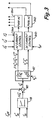
- FIG. 3 shows a functional block diagram of converter control 46 using mixed AC and DC sources 12 and 14 with power sharing.
- a battery will be described as a typical example of DC source 14.
- Shown in FIG. 3 are voltage regulator 78, summer 80, reference splitter 82, AC current control 84A, DC current control 84D, PWM-AC pulse generator 86A, and PWM-DC pulse generator 86D.
- Current reference I q * is created in the same way as for the three-phase AC power case shown in FIG. 2 and is split into two parts: (a) single phase AC converter current reference I q * * and (b) battery controller current reference I b * * .
- the factor k b ⁇ k b g k b m determines the relative contributions to the desired current reference I q * by DC power source 14 and by single phase AC source 12 (superscript g stands for regeneration, subscript m for motoring, and subscript b for battery).
- the factor k b can assume values between 0 and 1.
- k b * 0
- only the single phase AC converter formed by transistors 60R, 60S, 62R, and 62S will control DC bus 24; there will be no contribution from DC source 14 and transistors 60T and 62T.
- k b * 0.5
- the current reference will be split equally between single phase AC source 12 and DC source 14.
- DC power source 14 and transistors 60T and 62T will control voltage V dc on DC bus 24.
- AC current control 82 generates control signals used by PWM-AC pulse generator 86 to produce gating pulses to transistors 60R, 60S, 62R, and 62S.
- the control signals are a function of I q * * , I q f , I d f , and I d * .
- I q * * 1 ⁇ k b * I q * .
- DC current control generates control signals used by PWM-DC pulse generator to produce gating pulses to transistors 60T and 62T.
- the control signals are a function of k b * I b ′ *
- the loading of the leg of converter 22 operating from DC source 14 i.e., the circuit formed by transistors 60T and 62T) is a complex function of the ratio of the DC source voltage to the DC bus voltage, IGBT module design, free wheeling current rating, IGBT device rating, current direction, etc.
- DC bus voltage ripple is controlled by the DC source current.
- the ripple is controlled/eliminated by a feed forward signal I bff * is added to the DC source current reference k b * I q * at summer 102 to produce modified current reference I b * * at the input of DC current control 84D.
- Modified current reference I b * * is compared to feedback signal I bf by element - summer 96. The difference I b * * ⁇ I bf is provided as an input to current regulator 94.
- Feed forward term I bff * (which is proportional to I b_ac ) is added to the DC source current reference k b * I q * at summing junction 102.
- Feed forward term I bff * is generated from I b_ac after being passed through an inverse of the approximation of closed loop transfer function G Ib ⁇ 1 for DC source current control.
- DC bus voltage ripple is also controlled by DC bus voltage ripple regulator 92 in FIG. 4 .
- the output of ripple regulator 92 is added to the output of current regulator 94 by adder/summer 98 to produce the control signal input to PWM-DC pulse generator 86D.
- Ripple regulator 92 helps to remove AC components from the DC bus voltage by controlling an AC component in the DC bus voltage error signal ⁇ dc .
- K p and K i are regulator gains
- the output of DC bus voltage ripple regulator 92 is shown in Equation (10) and is subtracted from the output of current regulator 94 by adder/summer 98, as shown in FIG. 4 .
- operation of regenerative drive 20 may also include control logic within controller 44 to maintain charge level on the battery or supercapacitor at a desired state-of-charge set point or target.
- FIG. 5 is a functional block diagram of converter control 46 that is generally similar to the diagram shown in FIG. 3 , but with the addition of power comparator 110, multiplier 112, inverter 114, multiplier 116, state-of-charge monitor 118, and charge balance control 120 (which includes current integrator 122, summer/adder 124, and time constant divider 126 acting as a proportional regulator). These additional components maintain charge level at the state-of-change target.
- DC source current I b is integrated at integrator 122 to produce ⁇ Q, which is added with (-) sing by summer 124 to reference ⁇ Q*.
- Monitor 118 produces reference ⁇ Q* based upon sensed battery voltage V b battery temperature ⁇ and desired state of charge.
- charge balance control circuit 126 sets the reference for the DC source current and works toward-charging/discharging, equalizing charge on DC source 14.
- the idling period depends on the application; for example, for an elevator, it happens during loading passengers between floors or during time when traffic is slow and there are no demands for motion.
- Time constant T eq and level of charge imbalance will set the charging/discharging current reference ⁇ I b * , which is added to k b * I b * by summer 102 to produce current reference I b * * for current control 84D.
- charging/discharging current is increased with DC source 14 being more charged/discharged.
- the speed of the charge balancing depends on the time constant T eq . For longer time constant, it will take more time for charge to balance, however, charging current will be smaller.
- converter control 46 controls converter 22 to increase power capacity through power sharing of AC source 12 and DC source 14, to reduce DC bus voltage ripple, and to maintain state-of-charge of DC source 14.
- Powering a three-phase regenerative drive from a combination of a single phase AC source and a DC source expands the capability of a drive when compared to a regenerative drive powered by a single phase AC source alone.
- the power rating of the drive is increased by using both AC and DC sources, and provides a redundancy in case one of the sources of energy is lost or not available.
- a loss of single phase AC power may still allow a regenerative drive to operate at a full or reduced performance level depending on the power demand of the load.
- Other approaches for dealing with loss or unavailability of three-phase AC power or the availability of only single phase power involve more expensive systems.
- one possible solution to lack of three-phase AC power from the utility power grid involves the addition of an on-site three-phase power generator, such as diesel motor/generator set as an alternative source of three-phase power to the utility power grid.
- Other approaches involve connecting a high voltage DC source directly to the regenerative drive, or connecting a lower voltage DC source with a separate DC/DC converter to provide all of the power for the regenerative drive.
- These solutions also involve additional cost.
- the input power converter of the regenerative drive could be redesigned to be able to handle the much higher currents needed from a single phase source in order to provide high enough power to operate the regenerative drive. This also requires providing a single phase feeder with high enough power to meet the power demands of the regenerative drive. Once again, this represents a more expensive approach than the mixed single-phase AC and DC power sources used in power system 10.
- converter control 46 splits the current reference from the DC bus voltage regulator into two parts. One part is used for controlling current from and to single-phase AC source 12. The other is used for controlling current from and to the DC source 14.
- a contribution or sharing factor k b a ratio of power from DC source 14 to total power demand is defined.
- the factor k b can be selected as a function of capability of AC source 12 or DC source 14 and associated power electronic devices, the mode of operation (e.g., generation, idling, or motoring), the level or state of charge of the DC power source, traffic profiles, seasonal or hourly utility rates, and so on.
- the selection of factor K b may be made, for example, by supervisory control 50 and provided to converter control 46.
- the use of power from DC source 14 in conjunction with power from single-phase AC source 12 provides opportunities to reduce voltage ripple on DC bus 24.
- the reductions in ripple are achieved by several different aspects.
- Second, the current reference that controls current from DC source 14 can by shaped to augment lapses in power flow from single-phase AC source 12.
- Third, using a signal containing the DC bus voltage ripple and providing it to a ripple regulator allows adjustment of the AC component in DC source current to reduce or eliminate ripple from DC bus voltage.
- the control of the current to and from DC source 14 can also take into account a state-of-charge target for DC source 14.
Landscapes
- Engineering & Computer Science (AREA)
- Automation & Control Theory (AREA)
- Power Engineering (AREA)
- Inverter Devices (AREA)
- Control Of Ac Motors In General (AREA)
- Rectifiers (AREA)
- Control Of Multiple Motors (AREA)
Claims (15)
- Entraînement régénératif triphasé comprenant :un convertisseur triphasé (22) ayant des entrées pour une connexion à une source CA monophasée et une source CC ;un onduleur triphasé (28) pour une connexion à un moteur ;un bus CC (24) connecté entre le convertisseur triphasé et l'onduleur triphasé ; et caractérisé parun contrôleur (46, 48) pour la fourniture de signaux de commande au convertisseur triphasé pour contrôler des contributions respectives à la demande de courant par la source CA monophasée et la source CC.
- Entraînement régénératif triphasé selon la revendication 1, dans lequel le convertisseur triphasé comprend :un premier circuit comprenant un premier ensemble de transistors de puissance (64) pour le contrôle du débit de courant entre la source CA monophasée et le bus CC ; etun second circuit comprenant un second ensemble de transistors de puissance (66) pour le contrôle du débit de courant entre la source CC et le bus CC.
- Entraînement régénératif triphasé selon la revendication 2, dans lequel les signaux de commande incluent un premier ensemble de signaux de modulation de largeur d'impulsions (PWM) pour contrôler le premier ensemble de transistors de puissance et un second ensemble de signaux de modulation de largeur d'impulsions (PWM) pour contrôler le second ensemble de transistors de puissance.
- Entraînement régénératif triphasé selon la revendication 3, dans lequel le contrôleur comprend :un régulateur de tension (78) pour la production d'une référence de courant en fonction d'une tension de bus CC et d'une tension de référence ;un séparateur de référence (82) pour la séparation de la référence de courant en une première référence associée à la source CA monophasée et une seconde référence associée à la source CC ;un contrôle de courant CA (84A) pour la génération d'un signal de commande de courant CA basé sur la première référence ;un premier générateur PWM (86A) pour la génération du premier ensemble de signaux PWM en fonction du signal de commande de courant CA ;un contrôle de courant CC (84D) pour la génération d'un signal de commande de courant CC basé sur la seconde référence ; etun second générateur PWM (86D) pour la génération du second ensemble de signaux PWM en fonction du signal de commande de courant CC.
- Entraînement régénératif triphasé selon la revendication 4 et comprenant en outre :un capteur de courant (30) pour la production d'un signal de rétroaction en fonction du débit de courant détecté entre la source CC et le bus CC ; etdans lequel le contrôle de courant CC génère le signal de commande de courant CC basé sur la seconde référence et le signal de rétroaction.
- Entraînement régénératif triphasé selon la revendication 5 dans lequel le contrôleur comprend en outre :un régulateur d'ondulation (92) pour la production d'un signal de correction d'ondulation en fonction d'une ondulation de tension de bus CC ; etdans lequel le contrôle de courant CC génère le signal de commande de courant CC basé sur la seconde référence, le signal de rétroaction, et le signal de correction d'ondulation.
- Entraînement régénératif triphasé selon la revendication 4 et comprenant en outre :un circuit (90) pour la production d'un signal d'antéréaction en fonction d'un composant CA de débit de courant de la source CC ; etun coupleur de signal (100) pour la modification de la seconde référence basée sur le signal d'antéréaction.
- Entraînement régénératif triphasé selon la revendication 4 et comprenant en outre :un contrôle d'état de charge pour la fourniture d'un signal de commande de charge basé sur un état de charge de la source CC et un débit de courant entre la source CC et le bus CC ; etun coupleur de signal pour la modification de la seconde référence basée sur le signal de commande de charge.
- Entraînement régénératif triphasé selon la revendication 4 dans lequel le séparateur de référence sépare la référence de courant sur la base d'un facteur de contribution, et de préférence dans lequel le facteur de contribution peut être sélectionné en fonction du mode de fonctionnement de l'entraînement régénératif, ou dans lequel le facteur de contribution peut être sélectionné en fonction d'au moins une capacité de la source CA monophasée, capacité de la source CA, capacité de composants du convertisseur triphasé et de l'onduleur triphasé, état de charge de la source CC, profils de trafic d'élévateur, et tarifs des services publics.
- Procédé de fonctionnement d'un entraînement régénératif comprenant un convertisseur, un onduleur et un bus CC connecté entre le convertisseur et l'onduleur, le procédé comprenant :la connexion d'une source CA monophasée et d'une source CC au convertisseur ;caractérisé parla création d'une référence de courant en fonction d'une tension de bus CC ;la séparation de la référence de courant en une première référence et une seconde référence ;le contrôle du débit de courant dans le convertisseur entre la source CA monophasée et le bus CC en fonction de la première référence ; etle contrôle du débit de courant dans le convertisseur entre la source CC et le bus CC en fonction de la seconde référence.
- Procédé selon la revendication 10 dans lequel la séparation de la référence de courant est basée sur un facteur de contribution, et de préférence dans lequel le facteur de contribution est fonction du fait que l'entraînement régénératif est dans un mode de fonctionnement en moteur, un mode inactif, ou un mode de régénération, ou dans lequel le facteur de contribution peut être sélectionné sur la base d'au moins une capacité de la source CA monophasée, capacité de la source CC, capacité de composants du convertisseur et de l'onduleur, état de charge de la source CC, et tarifs des services publics.
- Procédé selon la revendication 10 et comprenant en outre :la production d'un signal de correction d'ondulation en fonction d'une ondulation de tension de bus CC ; etla modification du débit de courant entre la source CC et le bus CC basée sur le signal de correction d'ondulation.
- Procédé selon la revendication 10 et comprenant en outre :la production d'un signal d'antéréaction en fonction d'un composant CA de débit de courant de la source CC ; etla modification de la seconde référence basée sur le signal d'antéréaction.
- Procédé selon la revendication 10 et comprenant en outre :la production d'un signal de commande de charge en fonction d'un état de charge de la source CC ; etla modification de la seconde référence basée sur le signal de commande de charge.
- Procédé selon la revendication 10 et comprenant en outre :la détermination de la demande de puissance sur l'entraînement régénératif ; etla séparation de la référence de courant de telle sorte que la première référence soit égale à la référence de courant et que la seconde référence soit de zéro lorsque la demande de puissance est inférieure à une valeur de seuil.
Applications Claiming Priority (1)
| Application Number | Priority Date | Filing Date | Title |
|---|---|---|---|
| PCT/US2008/012992 WO2010059141A1 (fr) | 2008-11-21 | 2008-11-21 | Fonctionnement d'un entraînement régénératif triphasé à partir de sources d'alimentation en courant continu et en courant alternatif monophasé mélangées |
Publications (3)
| Publication Number | Publication Date |
|---|---|
| EP2358623A1 EP2358623A1 (fr) | 2011-08-24 |
| EP2358623A4 EP2358623A4 (fr) | 2014-11-05 |
| EP2358623B1 true EP2358623B1 (fr) | 2016-05-04 |
Family
ID=42198381
Family Applications (1)
| Application Number | Title | Priority Date | Filing Date |
|---|---|---|---|
| EP08878318.8A Active EP2358623B1 (fr) | 2008-11-21 | 2008-11-21 | Fonctionnement d'un entraînement régénératif triphasé à partir de sources d'alimentation en courant continu et en courant alternatif monophasé mélangées |
Country Status (6)
| Country | Link |
|---|---|
| US (1) | US8629637B2 (fr) |
| EP (1) | EP2358623B1 (fr) |
| JP (1) | JP5526145B2 (fr) |
| CN (1) | CN102224097B (fr) |
| ES (1) | ES2571939T3 (fr) |
| WO (1) | WO2010059141A1 (fr) |
Families Citing this family (45)
| Publication number | Priority date | Publication date | Assignee | Title |
|---|---|---|---|---|
| ES2943547T3 (es) * | 2008-11-17 | 2023-06-14 | Otis Elevator Co | Calibración del estado de carga de la batería |
| FI122048B (fi) * | 2009-06-01 | 2011-07-29 | Kone Corp | Kuljetusjärjestelmä |
| EP2598425B1 (fr) * | 2010-07-30 | 2020-02-26 | Otis Elevator Company | Commande régénératrice d'entraînement d'ascenseur référencée à un bus cc |
| CN102255550B (zh) * | 2011-07-04 | 2013-10-16 | 华北电力大学 | 基于三相桥式逆变电路的电源裂相装置及其控制方法 |
| EP2748917B1 (fr) * | 2011-08-24 | 2018-05-30 | ABB Schweiz AG | Convertisseur cc-cc bidirectionnel non-isolé avec des cellules en cascade |
| RU2476331C1 (ru) * | 2012-01-30 | 2013-02-27 | Анатолий Александрович Рыбаков | Способ стабилизации оптимальной угловой скорости якоря электрогенератора силовой установки при рекуперации кинетической энергии торможения |
| ITFI20120030A1 (it) * | 2012-02-20 | 2013-08-21 | Fulvio Soldaini | Dispositivo di controllo e recupero dell'energia. |
| US8988026B2 (en) * | 2012-07-31 | 2015-03-24 | Rockwell Automation Technologies, Inc. | Single phase operation of a three-phase drive system |
| CN103633892A (zh) * | 2012-08-27 | 2014-03-12 | 成都酷玩网络科技有限公司 | 单阻尼混合三角连接无振制动变频装置 |
| CN103633894A (zh) * | 2012-08-28 | 2014-03-12 | 成都酷玩网络科技有限公司 | 双阻尼单电阻星形连接无振制动变频装置 |
| KR101677784B1 (ko) * | 2012-09-05 | 2016-11-18 | 엘에스산전 주식회사 | 회생형 인버터 장치 및 단위 전력 셀을 이용한 인버터 장치 |
| KR101661379B1 (ko) * | 2012-10-29 | 2016-09-29 | 엘에스산전 주식회사 | 인버터에서 직류단 커패시터의 용량 추정장치 |
| WO2014182291A1 (fr) * | 2013-05-08 | 2014-11-13 | Otis Elevator Company | Batterie d'accumulateurs chargée par énergie hybride ou topologies d'attaque alimentées par supercondensateurs |
| WO2015023263A1 (fr) | 2013-08-13 | 2015-02-19 | Otis Elevator Company | Freinage d'ascenseur dans un système d'ascenseur alimenté par une batterie |
| KR102227416B1 (ko) * | 2013-12-18 | 2021-03-12 | 오티스 엘리베이터 컴파니 | 다중레벨 회생 드라이브를 위한 pwm 전략 |
| AU2013408350B2 (en) * | 2013-12-18 | 2017-02-23 | Otis Elevator Company | Multilevel drive half DC bus power supplies |
| PL406640A1 (pl) * | 2013-12-23 | 2015-07-06 | Politechnika Krakowska im. Tadeusza Kościuszki | Energooszczędny system transportu wsadu w zespole prasa-piec |
| WO2015198455A1 (fr) * | 2014-06-26 | 2015-12-30 | 三菱電機株式会社 | Dispositif de commande de positionnement |
| WO2016100026A1 (fr) * | 2014-12-17 | 2016-06-23 | Otis Elevator Company | Système de transport à circuits d'attaque parallèles |
| GB2538493B (en) * | 2015-05-12 | 2017-05-10 | Invertek Drives Ltd | A control method and system |
| CN104843568A (zh) * | 2015-05-29 | 2015-08-19 | 西继迅达(许昌)电梯有限公司 | 一种电梯数字化伺服驱动器 |
| JP6797892B2 (ja) * | 2015-07-28 | 2020-12-09 | コーニンクレッカ フィリップス エヌ ヴェKoninklijke Philips N.V. | 電気モータのための制動エネルギー回生システム、及び方法 |
| US9800188B2 (en) * | 2015-09-15 | 2017-10-24 | Regal Beloit America, Inc. | Hybrid drive circuit for variable speed induction motor |
| US10294070B2 (en) * | 2015-11-18 | 2019-05-21 | Premco, Inc. | Regenerative electrical power supply for elevators |
| CN109075599B (zh) * | 2016-04-14 | 2021-12-07 | 东芝三菱电机产业系统株式会社 | 不间断电源装置 |
| GB201610369D0 (en) * | 2016-06-15 | 2016-07-27 | Rolls Royce Plc | Control of an electrical converter |
| WO2018073909A1 (fr) * | 2016-10-19 | 2018-04-26 | 三菱電機株式会社 | Dispositif onduleur et procédé d'arrêt de dispositif onduleur |
| DE102016122672B4 (de) * | 2016-11-24 | 2018-11-22 | Infineon Technologies Ag | Verfahren zum Betreiben eines Sensors und Sensor |
| US10566881B2 (en) | 2017-01-27 | 2020-02-18 | Franklin Electric Co., Inc. | Motor drive system including removable bypass circuit and/or cooling features |
| US10468968B2 (en) | 2017-03-17 | 2019-11-05 | Continental Powertrain USA, LLC | Pi source inverter-converter for hybrid electric vehicles |
| US10917029B2 (en) | 2017-03-17 | 2021-02-09 | Vitesco Technologies USA, LLC | Pi source inverter-converter for hybrid electric vehicles |
| DK3403971T3 (da) * | 2017-05-19 | 2021-01-25 | Kone Corp | Fremgangsmåde til at udføre en manuel kørsel i en elevator efter strømafbrydelse |
| EP3644493B1 (fr) * | 2017-06-21 | 2023-04-26 | Toshiba Mitsubishi-Electric Industrial Systems Corporation | Dispositif de démarrage de thyristor |
| US11482942B2 (en) | 2017-10-31 | 2022-10-25 | Otis Elevator Company | Single phase operation of three phase regenerative drives |
| US10381968B2 (en) * | 2017-12-05 | 2019-08-13 | Otis Elevator Company | Converter pulse width modulation strategies for three phase regenerative drives |
| US10320306B1 (en) | 2017-12-22 | 2019-06-11 | Hamilton Sundstrand Corporation | Matrix converter system with current control mode operation |
| CN108599251A (zh) * | 2018-05-21 | 2018-09-28 | 日立楼宇技术(广州)有限公司 | 电梯串联式能量回馈控制方法和系统 |
| EP3640176B1 (fr) | 2018-10-19 | 2022-02-16 | Otis Elevator Company | Gestion de la puissance dans un système d'ascenseur |
| WO2020128066A1 (fr) * | 2018-12-20 | 2020-06-25 | Volvo Truck Corporation | Procédé amélioré de commande d'un système de stockage d'énergie |
| US10587214B1 (en) * | 2019-03-22 | 2020-03-10 | Hamilton Sundstrand Corporation | Matrix converter operation in current control mode with regulation of output voltage vector |
| WO2021211630A2 (fr) * | 2020-04-14 | 2021-10-21 | Tae Technologies, Inc. | Systèmes, dispositifs et procédés pour charger et décharger des systèmes d'énergie en cascade utilisant des modules |
| WO2022213057A1 (fr) * | 2021-03-31 | 2022-10-06 | Portland State University | Convertisseur de puissance multiniveau modulaire ultra-dense |
| CN115313802B (zh) * | 2022-07-19 | 2025-09-16 | 广东美的白色家电技术创新中心有限公司 | 背靠背变换器控制方法、装置及电子设备 |
| US12233716B2 (en) | 2022-09-23 | 2025-02-25 | Ford Global Technologies, Llc | Automotive electric drive with three phase coupled inverter |
| US20240275313A1 (en) * | 2023-02-09 | 2024-08-15 | Otis Elevator Company | Elevator machine braking |
Family Cites Families (17)
| Publication number | Priority date | Publication date | Assignee | Title |
|---|---|---|---|---|
| US4386394A (en) * | 1981-05-20 | 1983-05-31 | General Electric Company | Single phase and three phase AC to DC converters |
| JPS61135392A (ja) * | 1984-12-03 | 1986-06-23 | Hitachi Ltd | エレベ−タ−駆動方式 |
| JPS61248881A (ja) * | 1985-04-22 | 1986-11-06 | 三菱電機株式会社 | エレベ−タの制御装置 |
| JPS63178789A (ja) | 1987-01-20 | 1988-07-22 | Hitachi Elevator Eng & Serv Co Ltd | エレベ−タの運転装置 |
| US5058710A (en) * | 1990-08-14 | 1991-10-22 | Otis Elevator Company | Elevator power source device |
| JPH0632553A (ja) * | 1992-07-16 | 1994-02-08 | Hitachi Ltd | エレベータ装置 |
| JP2791273B2 (ja) * | 1993-09-07 | 1998-08-27 | 株式会社東芝 | 電力変換装置 |
| GB9400499D0 (en) | 1994-01-12 | 1994-03-09 | Magnum Power Solutions Ltd | Improved uninterruptible power supply |
| JP2001008459A (ja) | 1999-06-18 | 2001-01-12 | Hitachi Ltd | エレベーターの制御装置 |
| CN100407545C (zh) | 1999-11-17 | 2008-07-30 | 富士达株式会社 | 交流电梯的电源装置 |
| JP4503750B2 (ja) | 1999-12-24 | 2010-07-14 | フジテック株式会社 | 交流エレベータの電源装置 |
| DE69942790D1 (de) * | 1999-12-15 | 2010-11-04 | Mitsubishi Electric Corp | Regler zur Durchführung einer Entkopplungsregelung eines Blindleistungsserienkompensators |
| JP2003002562A (ja) * | 2001-06-25 | 2003-01-08 | Sugiyasu Industries Co Ltd | 階段昇降機 |
| US6636012B2 (en) * | 2001-09-28 | 2003-10-21 | Rockwell Automation Technologies, Inc. | Stator and rotor resistance identifier using high frequency injection |
| US20040262996A1 (en) * | 2003-06-30 | 2004-12-30 | Olsen Ib Ingemann | Phase conversion device with built-in demand reduction / power boosting. |
| US7609534B2 (en) | 2004-08-19 | 2009-10-27 | Otis Elevator Company | Operating a three phase device using single phase power |
| JP4634817B2 (ja) | 2005-02-22 | 2011-02-16 | 株式会社Ihi | 負荷駆動装置 |
-
2008
- 2008-11-21 EP EP08878318.8A patent/EP2358623B1/fr active Active
- 2008-11-21 JP JP2011537402A patent/JP5526145B2/ja not_active Expired - Fee Related
- 2008-11-21 ES ES08878318T patent/ES2571939T3/es active Active
- 2008-11-21 WO PCT/US2008/012992 patent/WO2010059141A1/fr not_active Ceased
- 2008-11-21 CN CN200880132089.XA patent/CN102224097B/zh active Active
- 2008-11-21 US US13/128,798 patent/US8629637B2/en active Active
Also Published As
| Publication number | Publication date |
|---|---|
| CN102224097B (zh) | 2014-04-16 |
| US20110247900A1 (en) | 2011-10-13 |
| JP5526145B2 (ja) | 2014-06-18 |
| WO2010059141A1 (fr) | 2010-05-27 |
| WO2010059141A9 (fr) | 2011-06-23 |
| ES2571939T3 (es) | 2016-05-27 |
| JP2012509655A (ja) | 2012-04-19 |
| US8629637B2 (en) | 2014-01-14 |
| EP2358623A1 (fr) | 2011-08-24 |
| CN102224097A (zh) | 2011-10-19 |
| EP2358623A4 (fr) | 2014-11-05 |
| HK1163044A1 (en) | 2012-09-07 |
Similar Documents
| Publication | Publication Date | Title |
|---|---|---|
| US8629637B2 (en) | Operation of a three-phase regenerative drive from mixed DC and single phase AC power sources | |
| EP2117983B1 (fr) | Operation de sauvetage automatique pour systeme d'entrainement regenerateur | |
| US8590672B2 (en) | Management of power from multiple sources in an elevator power system | |
| US8146714B2 (en) | Elevator system including regenerative drive and rescue operation circuit for normal and power failure conditions | |
| EP2326587B1 (fr) | Commande de courant de ligne et de stockage d énergie pour dispositif d entraînement d ascenseur | |
| US6435311B2 (en) | Elevator control calculating power consumed and power generated by a controlled elevator | |
| US8471403B2 (en) | Power supply arrangement of an elevator | |
| WO2010042118A1 (fr) | Bâtiment à multiples sources de génération d’énergie activées par un système d’ascenseur | |
| Dalala et al. | Energy recovery control in elevators with automatic rescue application | |
| EP3450376B1 (fr) | Système de sauvetage et de charge automatique pour entraînement d'ascenseur | |
| JP3577543B2 (ja) | 複数台エレベータの制御装置 | |
| Iannuzzi et al. | Use of supercapacitors for energy saving in overhead travelling crane drives | |
| CN112803437A (zh) | 用于电网频率调节的动力电池充/放电控制系统 | |
| HK1163044B (en) | Operation of a three-phase regenerative drive from mixed dc and single phase ac power sources | |
| Raghava et al. | Comparative study of recent advancements in regenerative drives in elevator systems | |
| WO2010019123A1 (fr) | Gestion de puissance provenant de multiples sources dans un système de puissance d’ascenseur | |
| HK1159590B (en) | Management of power from multiple sources in an elevator power system | |
| HK1124300A1 (en) | Elevator power system |
Legal Events
| Date | Code | Title | Description |
|---|---|---|---|
| PUAI | Public reference made under article 153(3) epc to a published international application that has entered the european phase |
Free format text: ORIGINAL CODE: 0009012 |
|
| 17P | Request for examination filed |
Effective date: 20110621 |
|
| AK | Designated contracting states |
Kind code of ref document: A1 Designated state(s): AT BE BG CH CY CZ DE DK EE ES FI FR GB GR HR HU IE IS IT LI LT LU LV MC MT NL NO PL PT RO SE SI SK TR |
|
| DAX | Request for extension of the european patent (deleted) | ||
| A4 | Supplementary search report drawn up and despatched |
Effective date: 20141006 |
|
| RIC1 | Information provided on ipc code assigned before grant |
Ipc: H02P 27/00 20060101ALI20140929BHEP Ipc: B66B 1/30 20060101AFI20140929BHEP Ipc: H02P 27/06 20060101ALI20140929BHEP |
|
| GRAP | Despatch of communication of intention to grant a patent |
Free format text: ORIGINAL CODE: EPIDOSNIGR1 |
|
| INTG | Intention to grant announced |
Effective date: 20151118 |
|
| GRAS | Grant fee paid |
Free format text: ORIGINAL CODE: EPIDOSNIGR3 |
|
| GRAA | (expected) grant |
Free format text: ORIGINAL CODE: 0009210 |
|
| AK | Designated contracting states |
Kind code of ref document: B1 Designated state(s): AT BE BG CH CY CZ DE DK EE ES FI FR GB GR HR HU IE IS IT LI LT LU LV MC MT NL NO PL PT RO SE SI SK TR |
|
| REG | Reference to a national code |
Ref country code: GB Ref legal event code: FG4D |
|
| REG | Reference to a national code |
Ref country code: CH Ref legal event code: EP |
|
| REG | Reference to a national code |
Ref country code: AT Ref legal event code: REF Ref document number: 796722 Country of ref document: AT Kind code of ref document: T Effective date: 20160515 |
|
| REG | Reference to a national code |
Ref country code: ES Ref legal event code: FG2A Ref document number: 2571939 Country of ref document: ES Kind code of ref document: T3 Effective date: 20160527 |
|
| REG | Reference to a national code |
Ref country code: IE Ref legal event code: FG4D |
|
| REG | Reference to a national code |
Ref country code: DE Ref legal event code: R096 Ref document number: 602008044128 Country of ref document: DE |
|
| REG | Reference to a national code |
Ref country code: NL Ref legal event code: MP Effective date: 20160504 |
|
| REG | Reference to a national code |
Ref country code: LT Ref legal event code: MG4D |
|
| REG | Reference to a national code |
Ref country code: FR Ref legal event code: PLFP Year of fee payment: 9 |
|
| PG25 | Lapsed in a contracting state [announced via postgrant information from national office to epo] |
Ref country code: FI Free format text: LAPSE BECAUSE OF FAILURE TO SUBMIT A TRANSLATION OF THE DESCRIPTION OR TO PAY THE FEE WITHIN THE PRESCRIBED TIME-LIMIT Effective date: 20160504 Ref country code: NL Free format text: LAPSE BECAUSE OF FAILURE TO SUBMIT A TRANSLATION OF THE DESCRIPTION OR TO PAY THE FEE WITHIN THE PRESCRIBED TIME-LIMIT Effective date: 20160504 Ref country code: NO Free format text: LAPSE BECAUSE OF FAILURE TO SUBMIT A TRANSLATION OF THE DESCRIPTION OR TO PAY THE FEE WITHIN THE PRESCRIBED TIME-LIMIT Effective date: 20160804 Ref country code: LT Free format text: LAPSE BECAUSE OF FAILURE TO SUBMIT A TRANSLATION OF THE DESCRIPTION OR TO PAY THE FEE WITHIN THE PRESCRIBED TIME-LIMIT Effective date: 20160504 |
|
| REG | Reference to a national code |
Ref country code: AT Ref legal event code: MK05 Ref document number: 796722 Country of ref document: AT Kind code of ref document: T Effective date: 20160504 |
|
| PG25 | Lapsed in a contracting state [announced via postgrant information from national office to epo] |
Ref country code: LV Free format text: LAPSE BECAUSE OF FAILURE TO SUBMIT A TRANSLATION OF THE DESCRIPTION OR TO PAY THE FEE WITHIN THE PRESCRIBED TIME-LIMIT Effective date: 20160504 Ref country code: GR Free format text: LAPSE BECAUSE OF FAILURE TO SUBMIT A TRANSLATION OF THE DESCRIPTION OR TO PAY THE FEE WITHIN THE PRESCRIBED TIME-LIMIT Effective date: 20160805 Ref country code: PT Free format text: LAPSE BECAUSE OF FAILURE TO SUBMIT A TRANSLATION OF THE DESCRIPTION OR TO PAY THE FEE WITHIN THE PRESCRIBED TIME-LIMIT Effective date: 20160905 Ref country code: SE Free format text: LAPSE BECAUSE OF FAILURE TO SUBMIT A TRANSLATION OF THE DESCRIPTION OR TO PAY THE FEE WITHIN THE PRESCRIBED TIME-LIMIT Effective date: 20160504 Ref country code: HR Free format text: LAPSE BECAUSE OF FAILURE TO SUBMIT A TRANSLATION OF THE DESCRIPTION OR TO PAY THE FEE WITHIN THE PRESCRIBED TIME-LIMIT Effective date: 20160504 |
|
| PG25 | Lapsed in a contracting state [announced via postgrant information from national office to epo] |
Ref country code: IT Free format text: LAPSE BECAUSE OF FAILURE TO SUBMIT A TRANSLATION OF THE DESCRIPTION OR TO PAY THE FEE WITHIN THE PRESCRIBED TIME-LIMIT Effective date: 20160504 |
|
| PG25 | Lapsed in a contracting state [announced via postgrant information from national office to epo] |
Ref country code: SK Free format text: LAPSE BECAUSE OF FAILURE TO SUBMIT A TRANSLATION OF THE DESCRIPTION OR TO PAY THE FEE WITHIN THE PRESCRIBED TIME-LIMIT Effective date: 20160504 Ref country code: RO Free format text: LAPSE BECAUSE OF FAILURE TO SUBMIT A TRANSLATION OF THE DESCRIPTION OR TO PAY THE FEE WITHIN THE PRESCRIBED TIME-LIMIT Effective date: 20160504 Ref country code: DK Free format text: LAPSE BECAUSE OF FAILURE TO SUBMIT A TRANSLATION OF THE DESCRIPTION OR TO PAY THE FEE WITHIN THE PRESCRIBED TIME-LIMIT Effective date: 20160504 Ref country code: EE Free format text: LAPSE BECAUSE OF FAILURE TO SUBMIT A TRANSLATION OF THE DESCRIPTION OR TO PAY THE FEE WITHIN THE PRESCRIBED TIME-LIMIT Effective date: 20160504 Ref country code: CZ Free format text: LAPSE BECAUSE OF FAILURE TO SUBMIT A TRANSLATION OF THE DESCRIPTION OR TO PAY THE FEE WITHIN THE PRESCRIBED TIME-LIMIT Effective date: 20160504 |
|
| REG | Reference to a national code |
Ref country code: DE Ref legal event code: R097 Ref document number: 602008044128 Country of ref document: DE |
|
| PG25 | Lapsed in a contracting state [announced via postgrant information from national office to epo] |
Ref country code: BE Free format text: LAPSE BECAUSE OF FAILURE TO SUBMIT A TRANSLATION OF THE DESCRIPTION OR TO PAY THE FEE WITHIN THE PRESCRIBED TIME-LIMIT Effective date: 20160504 Ref country code: AT Free format text: LAPSE BECAUSE OF FAILURE TO SUBMIT A TRANSLATION OF THE DESCRIPTION OR TO PAY THE FEE WITHIN THE PRESCRIBED TIME-LIMIT Effective date: 20160504 Ref country code: PL Free format text: LAPSE BECAUSE OF FAILURE TO SUBMIT A TRANSLATION OF THE DESCRIPTION OR TO PAY THE FEE WITHIN THE PRESCRIBED TIME-LIMIT Effective date: 20160504 |
|
| PLBE | No opposition filed within time limit |
Free format text: ORIGINAL CODE: 0009261 |
|
| STAA | Information on the status of an ep patent application or granted ep patent |
Free format text: STATUS: NO OPPOSITION FILED WITHIN TIME LIMIT |
|
| 26N | No opposition filed |
Effective date: 20170207 |
|
| PG25 | Lapsed in a contracting state [announced via postgrant information from national office to epo] |
Ref country code: SI Free format text: LAPSE BECAUSE OF FAILURE TO SUBMIT A TRANSLATION OF THE DESCRIPTION OR TO PAY THE FEE WITHIN THE PRESCRIBED TIME-LIMIT Effective date: 20160504 |
|
| REG | Reference to a national code |
Ref country code: CH Ref legal event code: PL |
|
| REG | Reference to a national code |
Ref country code: DE Ref legal event code: R082 Ref document number: 602008044128 Country of ref document: DE Representative=s name: SCHMITT-NILSON SCHRAUD WAIBEL WOHLFROM PATENTA, DE |
|
| GBPC | Gb: european patent ceased through non-payment of renewal fee |
Effective date: 20161121 |
|
| PG25 | Lapsed in a contracting state [announced via postgrant information from national office to epo] |
Ref country code: LI Free format text: LAPSE BECAUSE OF NON-PAYMENT OF DUE FEES Effective date: 20161130 Ref country code: CH Free format text: LAPSE BECAUSE OF NON-PAYMENT OF DUE FEES Effective date: 20161130 |
|
| REG | Reference to a national code |
Ref country code: IE Ref legal event code: MM4A |
|
| PG25 | Lapsed in a contracting state [announced via postgrant information from national office to epo] |
Ref country code: LU Free format text: LAPSE BECAUSE OF NON-PAYMENT OF DUE FEES Effective date: 20161130 |
|
| REG | Reference to a national code |
Ref country code: FR Ref legal event code: PLFP Year of fee payment: 10 |
|
| PG25 | Lapsed in a contracting state [announced via postgrant information from national office to epo] |
Ref country code: GB Free format text: LAPSE BECAUSE OF NON-PAYMENT OF DUE FEES Effective date: 20161121 Ref country code: IE Free format text: LAPSE BECAUSE OF NON-PAYMENT OF DUE FEES Effective date: 20161121 |
|
| PG25 | Lapsed in a contracting state [announced via postgrant information from national office to epo] |
Ref country code: HU Free format text: LAPSE BECAUSE OF FAILURE TO SUBMIT A TRANSLATION OF THE DESCRIPTION OR TO PAY THE FEE WITHIN THE PRESCRIBED TIME-LIMIT; INVALID AB INITIO Effective date: 20081121 Ref country code: CY Free format text: LAPSE BECAUSE OF FAILURE TO SUBMIT A TRANSLATION OF THE DESCRIPTION OR TO PAY THE FEE WITHIN THE PRESCRIBED TIME-LIMIT Effective date: 20160504 |
|
| PG25 | Lapsed in a contracting state [announced via postgrant information from national office to epo] |
Ref country code: IS Free format text: LAPSE BECAUSE OF FAILURE TO SUBMIT A TRANSLATION OF THE DESCRIPTION OR TO PAY THE FEE WITHIN THE PRESCRIBED TIME-LIMIT Effective date: 20160504 Ref country code: TR Free format text: LAPSE BECAUSE OF FAILURE TO SUBMIT A TRANSLATION OF THE DESCRIPTION OR TO PAY THE FEE WITHIN THE PRESCRIBED TIME-LIMIT Effective date: 20160504 Ref country code: MC Free format text: LAPSE BECAUSE OF FAILURE TO SUBMIT A TRANSLATION OF THE DESCRIPTION OR TO PAY THE FEE WITHIN THE PRESCRIBED TIME-LIMIT Effective date: 20160504 |
|
| PG25 | Lapsed in a contracting state [announced via postgrant information from national office to epo] |
Ref country code: BG Free format text: LAPSE BECAUSE OF FAILURE TO SUBMIT A TRANSLATION OF THE DESCRIPTION OR TO PAY THE FEE WITHIN THE PRESCRIBED TIME-LIMIT Effective date: 20160504 |
|
| PG25 | Lapsed in a contracting state [announced via postgrant information from national office to epo] |
Ref country code: MT Free format text: LAPSE BECAUSE OF NON-PAYMENT OF DUE FEES Effective date: 20161121 |
|
| REG | Reference to a national code |
Ref country code: FR Ref legal event code: PLFP Year of fee payment: 11 |
|
| PGFP | Annual fee paid to national office [announced via postgrant information from national office to epo] |
Ref country code: DE Payment date: 20251022 Year of fee payment: 18 |
|
| PGFP | Annual fee paid to national office [announced via postgrant information from national office to epo] |
Ref country code: FR Payment date: 20251023 Year of fee payment: 18 |
|
| PGFP | Annual fee paid to national office [announced via postgrant information from national office to epo] |
Ref country code: ES Payment date: 20251201 Year of fee payment: 18 |