EP2359793A1 - Badhebevorrichtung - Google Patents
Badhebevorrichtung Download PDFInfo
- Publication number
- EP2359793A1 EP2359793A1 EP10153361A EP10153361A EP2359793A1 EP 2359793 A1 EP2359793 A1 EP 2359793A1 EP 10153361 A EP10153361 A EP 10153361A EP 10153361 A EP10153361 A EP 10153361A EP 2359793 A1 EP2359793 A1 EP 2359793A1
- Authority
- EP
- European Patent Office
- Prior art keywords
- lift device
- chassis
- bath lift
- upright
- bathtub
- Prior art date
- Legal status (The legal status is an assumption and is not a legal conclusion. Google has not performed a legal analysis and makes no representation as to the accuracy of the status listed.)
- Withdrawn
Links
- 238000006073 displacement reaction Methods 0.000 claims description 3
- 238000000926 separation method Methods 0.000 claims 1
- 101100441413 Caenorhabditis elegans cup-15 gene Proteins 0.000 description 4
- 238000003287 bathing Methods 0.000 description 1
- 230000001419 dependent effect Effects 0.000 description 1
- 230000003467 diminishing effect Effects 0.000 description 1
- 238000004519 manufacturing process Methods 0.000 description 1
- 238000009877 rendering Methods 0.000 description 1
- 230000000284 resting effect Effects 0.000 description 1
Images


Classifications
-
- A—HUMAN NECESSITIES
- A61—MEDICAL OR VETERINARY SCIENCE; HYGIENE
- A61G—TRANSPORT, PERSONAL CONVEYANCES, OR ACCOMMODATION SPECIALLY ADAPTED FOR PATIENTS OR DISABLED PERSONS; OPERATING TABLES OR CHAIRS; CHAIRS FOR DENTISTRY; FUNERAL DEVICES
- A61G7/00—Beds specially adapted for nursing; Devices for lifting patients or disabled persons
- A61G7/10—Devices for lifting patients or disabled persons, e.g. special adaptations of hoists thereto
- A61G7/1001—Devices for lifting patients or disabled persons, e.g. special adaptations of hoists thereto specially adapted for specific applications
- A61G7/1003—Devices for lifting patients or disabled persons, e.g. special adaptations of hoists thereto specially adapted for specific applications mounted on or in combination with a bath-tub
-
- A—HUMAN NECESSITIES
- A61—MEDICAL OR VETERINARY SCIENCE; HYGIENE
- A61G—TRANSPORT, PERSONAL CONVEYANCES, OR ACCOMMODATION SPECIALLY ADAPTED FOR PATIENTS OR DISABLED PERSONS; OPERATING TABLES OR CHAIRS; CHAIRS FOR DENTISTRY; FUNERAL DEVICES
- A61G7/00—Beds specially adapted for nursing; Devices for lifting patients or disabled persons
- A61G7/10—Devices for lifting patients or disabled persons, e.g. special adaptations of hoists thereto
- A61G7/1049—Attachment, suspending or supporting means for patients
- A61G7/1059—Seats
-
- A—HUMAN NECESSITIES
- A61—MEDICAL OR VETERINARY SCIENCE; HYGIENE
- A61G—TRANSPORT, PERSONAL CONVEYANCES, OR ACCOMMODATION SPECIALLY ADAPTED FOR PATIENTS OR DISABLED PERSONS; OPERATING TABLES OR CHAIRS; CHAIRS FOR DENTISTRY; FUNERAL DEVICES
- A61G7/00—Beds specially adapted for nursing; Devices for lifting patients or disabled persons
- A61G7/10—Devices for lifting patients or disabled persons, e.g. special adaptations of hoists thereto
- A61G7/1073—Parts, details or accessories
- A61G7/1074—Devices foldable for storage
Definitions
- the present invention relates to a bath lift device for raising and lowering persons into or out of a bathtub, said device including a chassis adapted to rest, in use, on a floor of the bathtub and a slideably supported seat adapted to be movable between a raised position, in which the seat is correctly positioned to permit a person standing outside the bathtub to sit inside said seat, and a lowered position, in which said seat is positioned at the bottom of the bathtub.
- Bath lift devices have been widely used for aged or disabled people as a convenient means for entering or leaving a bathtub.
- a conventional bath lift device comprises two main parts, a fixed part resting, in use, on a floor of the bathtub and a movable part including the seat.
- the bath lift device uses a pair of guide pillars extending from the chassis onto which is slideably mountable a seat having a backrest from the rear of which extend a pair of guide collars dimensioned to be received on the guide pillars.
- the seat can be raised relative to the chassis till the guide collars are disconnected from the guide pillars.
- the aim of the present invention is therefore to provide a bath lift device in which the fixed part and the movable part can be easily separated, in which the movable part can be easily raised or lowered relative to the fixed part, in which the sitting position of the user is stable and in which the probability of a break of the elements constituting the bath lift device is low.
- a further aim of the present invention is also to provide a bath lift device easy and cheap to manufacture and lightweight.
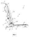
- the bath lift device 1 of the present invention mainly includes a fixed part 10 including a chassis 11-14 adapted to rest, in use, on a floor of the bathtub and a moveable part 20 including a seat frame 21 supporting a seat plate 22 and a backrest 23, said seat frame 21 being moveable upward and downward relative to the chassis 11-14 via a lifting means 24.
- the chassis 11-14 comprises two tubular upright elements 11 parallel to each other and extending, in use, in an approximately vertical direction. Said upright elements 11 are connected to their lower ends to a U-shaped element 14 via two connecting elements 13, said U-shaped element 14 extending, in use, in an approximately horizontal direction.
- each connecting element 13 is advantageously connected to said U-shaped element 14 so as to be positioned between an end section 14' of said U-shaped element 14 and the rest of said U-shaped element 14.
- each connecting element 13 could be connected at one end of said U-shaped element 14, an additional tubular element being connected to said connecting element 13 so as to form the end section 14' of Figure 2 .
- said connecting elements 13 are joined by a lateral rod 13' extending between the two lateral flanges of the U-shaped element 14.
- said upright elements 11 are also joined at their upper ends by a lateral element 12.
- said lateral element 12 consists in a curved tubular element 31 connected at its ends 32 to the two upper ends of the upright elements 11.
- Said curved element 31 is shaped so as to define an upper open area 33, delimited by the internal borders 34 of the curved element 31 and by the segment 35 joining said ends 32 in the plane defined the curved element 31.
- each suction cup 15 comprises a central section 16 fixedly connected to the U-shaped element 14 at its upper face, said section 16 having on its underface a concavity which acts as a sucker for temporarily connect said cup 15 to the floor of the bathtub.
- Each suction foot 15 comprises also at least one, but preferably two, peelable release tab 17 externally extending from the periphery of the central section 16, said tab 17 releasing the suction between the suction cup 15 and the floor of the bathtub when its free end 18 is raised.
- said tab 17 is equipped with a tubular section 18 at its free end. This tubular section 18 is configured so as to be entirely introduced inside a hole 19 formed in the underneath face of the U-shaped element 14 when the tab 17 is elastically twisted so as to align the longitudinal axis of said tubular section 18 with the longitudinal axis of the upright elements 11.
- Said tubular section 18 is also configured so as to be temporarily connected to said U-shaped element 14 when its longitudinal axis is perpendicular to the longitudinal axis of the upright elements 11.
- one solution consists in configuring said tubular section 18 so that its lenght is greater than the diameter of said hole 19.
- the moveable part 20 comprises a seat frame 21 formed by a first part 21', extending, in use, in an approximately horizontal direction, and by a second part 21 ", extending, in use, in an approximately vertical direction, said first part 21' supporting the seat plate 22 and said second part 21" supporting the backrest 23.
- Said first part 21' is configured as a U-shaped element and said second part 21" is configured as a pair of parallel upright elements fixedly connected at their lower ends to the U-shaped element.
- each upright element 21" is advantageously formed by a lower longitudinal section 21 "(a) and an upper longitudinal section 21 “(b), said sections 21 “(a) and 21 “(b) defining an approximately triangular form with the backrest 23.
- Said seat frame 21 is movable upward and downward relative to the chassis 11-14 via a lifting means 24 arranged on the rear of the backrest 23.
- the moveable part 20 comprises also two pairs of guiding rollers 25 rotatably connected to the upright elements 21" of said seat frame 21, each pair being slideably mounted onto one upright element 11 of the chassis 11-14 and the guiding rollers 25 of each pair being disposed, in use, on opposite sides of said one upright element 11.
- the guiding rollers 25 of each pair are advantageously positioned on the external lateral side of the lower section 21 "(a) of one upright element 21" such that the axes of rotation of said guiding rollers 25 are separated by a distance d, said distance d being greater than the diameter of the upright element 11, on which they are slideably mounted.
- the angle ⁇ between the plane containing said axes and the longitudinal axis defined by the upright element 11, on which they are slideably mounted is, in use, different from 90°.
- this configuration defines a four-points connection between the moveable part 20 and the fixed part 10 which confers a more stable sitting position for the user compared to the two-points connection when ⁇ is equal to 90 °.
- the distance d will be advantageously chosen such that said angle ⁇ is, in use, less than 45 degrees, and preferably less than 25 degrees. Indeed, by diminishing the angle ⁇ , which corresponds to an increased distance d, it is easier for the user to install the moveable part 20 on the fixed part 10 when said moveable part 20 is initially separated from said fixed part 10.
- the user positions the moveable part 20 relative to the fixed part 10 so that the angle ⁇ is greater than its value when the bath lift device 1 is in use and, in a second step, he lowers the moveable part 20 so that said moveable part 20 reaches a position limit and so that both upright elements 11 are continuously surrounded at two opposite sides by the guiding rollers 25 of each pair and, in a final step, he turns the moveable part 20 round so that the angle ⁇ reaches its value when the bath lift device 1 is in use.
- the upper rollers 25 of each pair, and respectively the lower rollers 25 of each pair are advantageously joined by an axle 26 extending, in use, in an approximately horizontal direction.
- a seat frame 21 comprising upright elements 21" that are completely straight.
- one guiding roller 25 of each pair will be connected to one upright element 21" by a lateral connecting rod extending in a close to perpendicular direction with regard to said upright element 21 ".
- the lifting means 24 used in the present invention will be configured so as to be lightweight and space-saving. Without to be bound by this specific solution, it will be advantageous to use a lifting means as described in the Canadian patent application CA 2 397 503 . In particular, such a lifting means prevents that a body part of a bathing person is trapped when the seat plate is moving downward. Accordingly, the lifting means 24 includes an outer spindle 24' within which is received a linearly extendable inner spindle tube (not shown), said outer spindle tube 24' being fixedly connected to the seat frame 21 and said inner spindle tube being supported at its lower end 24" by the chassis 11-14.
- said lower end 24" can be shaped as a fork adapted to be connected to the lateral rod 13' of the chassis 11-14.
- Said inner spindle is linearly extendable via an actuating means (not shown) contained within a housing 29, said housing 29 being fixedly connected to the rear of the backrest 23.
- the outer spindle tube 24' is connected to the axle 26 joining the lower rollers 25 of each pair. This connection is advantageously done by a clamping ring 27.
- said clamping ring 27 comprises a tubular section 40 inside which is received the outer spindle tube 24', said tubular section 40 comprising a radial aperture 41.
- the tubular section 40 is extended by two longitudinal sections 42, each section 42 comprising a pair of threaded holes 43 configured to join both sections 42 by two bolts (not shown).
- each section 42 comprising a pair of threaded holes 43 configured to join both sections 42 by two bolts (not shown).
- On the radially opposite side of the tubular section 40 with regard to said sections 42 extend two parallel flanges 44 from the periphery of said tubular section 40.
- Each flange 44 comprises a hole 45 adapted to receive the axle 26.
- said section 40 is advantageously formed by a first tubular section 46 and a second tubular section 47, said first section 46 having an internal diameter less than the internal diameter of said section 47.
- Said first section 46 is configured so as to be received inside a corresponding groove (not shown) of said outer spindle tube 24'.
- the depth of said groove will be advantageously greater than the difference between the internal diameters of said second section 47 and said first section 46.
- two extension plates 28 can be pivotally connected on both lateral ends of the seat plate 22, said extension plates 28 being configured so as to rest on the rim of the bathtub when the movable part 20 is positioned in a raised position so that the user can easily sit inside the bath lift device 1. Therefore, when said movable part 20 is lowered, said extension plates 28 are folded up so as to be positioned inside the bathtub.
- the backrest 23 comprises at least one rib 23', and preferably two ribs at both left and right sides of said backrest 23, said rib 23' extending in a perpendicular direction with regard to the rear of the backrest 23 and being approximately aligned, in use, with one upright element 11 of the chassis 11-14.
- Said rib 23 is adapted to contact said upright element 11 when the movable part 20 is tilting backwards with regard to the fixed part 10.
- Such a situation can occur when the lower end 24" of the inner spindle tube of the lifting means 24 is no more supported by the chassis 11-14. Therefore, such a configuration improves the safety of the bath lift device 1 as a whole.
Landscapes
- Health & Medical Sciences (AREA)
- Nursing (AREA)
- Life Sciences & Earth Sciences (AREA)
- Animal Behavior & Ethology (AREA)
- General Health & Medical Sciences (AREA)
- Public Health (AREA)
- Veterinary Medicine (AREA)
- Devices For Medical Bathing And Washing (AREA)
Priority Applications (4)
| Application Number | Priority Date | Filing Date | Title |
|---|---|---|---|
| EP10153361A EP2359793A1 (de) | 2010-02-11 | 2010-02-11 | Badhebevorrichtung |
| EP11707485.6A EP2533746B1 (de) | 2010-02-11 | 2011-02-11 | Badhebevorrichtung |
| EP15160037.6A EP2898868B9 (de) | 2010-02-11 | 2011-02-11 | Badhebevorrichtung |
| PCT/IB2011/050579 WO2011098974A2 (en) | 2010-02-11 | 2011-02-11 | Bath lift device |
Applications Claiming Priority (1)
| Application Number | Priority Date | Filing Date | Title |
|---|---|---|---|
| EP10153361A EP2359793A1 (de) | 2010-02-11 | 2010-02-11 | Badhebevorrichtung |
Publications (1)
| Publication Number | Publication Date |
|---|---|
| EP2359793A1 true EP2359793A1 (de) | 2011-08-24 |
Family
ID=42320572
Family Applications (3)
| Application Number | Title | Priority Date | Filing Date |
|---|---|---|---|
| EP10153361A Withdrawn EP2359793A1 (de) | 2010-02-11 | 2010-02-11 | Badhebevorrichtung |
| EP11707485.6A Not-in-force EP2533746B1 (de) | 2010-02-11 | 2011-02-11 | Badhebevorrichtung |
| EP15160037.6A Not-in-force EP2898868B9 (de) | 2010-02-11 | 2011-02-11 | Badhebevorrichtung |
Family Applications After (2)
| Application Number | Title | Priority Date | Filing Date |
|---|---|---|---|
| EP11707485.6A Not-in-force EP2533746B1 (de) | 2010-02-11 | 2011-02-11 | Badhebevorrichtung |
| EP15160037.6A Not-in-force EP2898868B9 (de) | 2010-02-11 | 2011-02-11 | Badhebevorrichtung |
Country Status (2)
| Country | Link |
|---|---|
| EP (3) | EP2359793A1 (de) |
| WO (1) | WO2011098974A2 (de) |
Citations (4)
| Publication number | Priority date | Publication date | Assignee | Title |
|---|---|---|---|---|
| GB2344047A (en) * | 1998-11-27 | 2000-05-31 | Sunrise Medical Ltd | Lifting device for use in a bath |
| EP1057467A1 (de) * | 1999-06-02 | 2000-12-06 | Dieter Gobbers | Ein- und Ausstiegshilfe für eine Badewanne |
| CA2397503A1 (en) | 2001-08-21 | 2003-02-21 | Aquatec Gmbh & Co. Kg | Bathtub lift for seniors and the handicapped |
| WO2005065621A2 (en) | 2004-01-08 | 2005-07-21 | Mountway Limited | Improvements in and relating to battery-operated bath lifts |
Family Cites Families (2)
| Publication number | Priority date | Publication date | Assignee | Title |
|---|---|---|---|---|
| CA2075932A1 (en) * | 1990-01-30 | 1991-07-31 | William A. B. Anscombe-Black | Bath seat assembly |
| SE522825C2 (sv) * | 2003-05-05 | 2004-03-09 | Arjo Hospital Equipment Ab | Patientstol med sits förskjutbar i höjdled |
-
2010
- 2010-02-11 EP EP10153361A patent/EP2359793A1/de not_active Withdrawn
-
2011
- 2011-02-11 EP EP11707485.6A patent/EP2533746B1/de not_active Not-in-force
- 2011-02-11 WO PCT/IB2011/050579 patent/WO2011098974A2/en not_active Ceased
- 2011-02-11 EP EP15160037.6A patent/EP2898868B9/de not_active Not-in-force
Patent Citations (4)
| Publication number | Priority date | Publication date | Assignee | Title |
|---|---|---|---|---|
| GB2344047A (en) * | 1998-11-27 | 2000-05-31 | Sunrise Medical Ltd | Lifting device for use in a bath |
| EP1057467A1 (de) * | 1999-06-02 | 2000-12-06 | Dieter Gobbers | Ein- und Ausstiegshilfe für eine Badewanne |
| CA2397503A1 (en) | 2001-08-21 | 2003-02-21 | Aquatec Gmbh & Co. Kg | Bathtub lift for seniors and the handicapped |
| WO2005065621A2 (en) | 2004-01-08 | 2005-07-21 | Mountway Limited | Improvements in and relating to battery-operated bath lifts |
Also Published As
| Publication number | Publication date |
|---|---|
| EP2898868A1 (de) | 2015-07-29 |
| EP2898868B9 (de) | 2017-03-15 |
| EP2533746A2 (de) | 2012-12-19 |
| WO2011098974A2 (en) | 2011-08-18 |
| EP2533746B1 (de) | 2015-03-25 |
| WO2011098974A3 (en) | 2011-11-10 |
| EP2898868B1 (de) | 2016-10-19 |
Similar Documents
| Publication | Publication Date | Title |
|---|---|---|
| US9597251B2 (en) | Sit-to-stand and walking assistive mobility aid | |
| KR101345273B1 (ko) | 이동식 환자 리프트 장치 | |
| AU2019208208B2 (en) | Mobility Aid | |
| EP3970583B1 (de) | Toilettenrahmen | |
| KR101013566B1 (ko) | 착석 및 기립 보조기구 | |
| FR2909550A1 (fr) | Lit medicalise a translation laterale | |
| JP2013508011A (ja) | 昇降駆動モジュールがヒンジ結合された昇降椅子 | |
| KR101689129B1 (ko) | 리프트수단이 구비된 의료용 보조로봇 | |
| EP2705818B1 (de) | Fußstützenvorrichtung | |
| KR102423485B1 (ko) | 승강과 이동이 가능한 하지마비 환자용 자동 승강-이동 체어 장치 | |
| CN104853708B (zh) | 供残疾人使用的升降装置 | |
| EP2359793A1 (de) | Badhebevorrichtung | |
| JP5666670B2 (ja) | 補助機構付きチェアー | |
| CN209210130U (zh) | 一种便于老人儿童用安全电梯 | |
| CN210961755U (zh) | 助力坐便装置 | |
| JP2012217718A (ja) | 便器用手摺 | |
| KR102816887B1 (ko) | 환자용 리프트 | |
| RU2445057C1 (ru) | Многопрофильное транспортное средство для инвалидов | |
| JP2011019805A (ja) | トイレ用手摺り装置 | |
| CN212308241U (zh) | 一种适用于轮椅的扶手结构 | |
| CN216754847U (zh) | U型管联动式移位机 | |
| CN217488486U (zh) | 老人如厕辅助装置 | |
| KR102619087B1 (ko) | 양변기 착석 및 기립 보조장치 | |
| RU2409339C2 (ru) | Подъемник передвижной для перемещения инвалидов | |
| EP3130322A1 (de) | Badehebevorrichtung |
Legal Events
| Date | Code | Title | Description |
|---|---|---|---|
| PUAI | Public reference made under article 153(3) epc to a published international application that has entered the european phase |
Free format text: ORIGINAL CODE: 0009012 |
|
| PUAI | Public reference made under article 153(3) epc to a published international application that has entered the european phase |
Free format text: ORIGINAL CODE: 0009012 |
|
| AK | Designated contracting states |
Kind code of ref document: A1 Designated state(s): AT BE BG CH CY CZ DE DK EE ES FI FR GB GR HR HU IE IS IT LI LT LU LV MC MK MT NL NO PL PT RO SE SI SK SM TR |
|
| AX | Request for extension of the european patent |
Extension state: AL BA RS |
|
| STAA | Information on the status of an ep patent application or granted ep patent |
Free format text: STATUS: THE APPLICATION IS DEEMED TO BE WITHDRAWN |
|
| 18D | Application deemed to be withdrawn |
Effective date: 20120225 |