EP2359896B1 - Dispositif d'électrodes pour la commande de courant ou de tension entre un appareil électromédical implantable et un lieu de thérapie et/ou diagnostic dans le corps humain - Google Patents
Dispositif d'électrodes pour la commande de courant ou de tension entre un appareil électromédical implantable et un lieu de thérapie et/ou diagnostic dans le corps humain Download PDFInfo
- Publication number
- EP2359896B1 EP2359896B1 EP11153009.3A EP11153009A EP2359896B1 EP 2359896 B1 EP2359896 B1 EP 2359896B1 EP 11153009 A EP11153009 A EP 11153009A EP 2359896 B1 EP2359896 B1 EP 2359896B1
- Authority
- EP
- European Patent Office
- Prior art keywords
- frequency
- electrode unit
- dependent transmission
- voltage
- transmission device
- Prior art date
- Legal status (The legal status is an assumption and is not a legal conclusion. Google has not performed a legal analysis and makes no representation as to the accuracy of the status listed.)
- Not-in-force
Links
- 238000003745 diagnosis Methods 0.000 title claims description 8
- 230000001419 dependent effect Effects 0.000 claims description 74
- 230000005540 biological transmission Effects 0.000 claims description 70
- 239000003990 capacitor Substances 0.000 claims description 41
- 239000004020 conductor Substances 0.000 claims description 23
- 238000002560 therapeutic procedure Methods 0.000 claims description 9
- 239000011248 coating agent Substances 0.000 claims description 7
- 238000000576 coating method Methods 0.000 claims description 7
- 230000003068 static effect Effects 0.000 claims description 4
- 238000009966 trimming Methods 0.000 claims description 4
- 230000005672 electromagnetic field Effects 0.000 claims description 2
- 230000006978 adaptation Effects 0.000 claims 1
- 238000010586 diagram Methods 0.000 description 11
- 238000002595 magnetic resonance imaging Methods 0.000 description 10
- 239000000463 material Substances 0.000 description 7
- 210000001519 tissue Anatomy 0.000 description 6
- 230000000747 cardiac effect Effects 0.000 description 5
- 230000008878 coupling Effects 0.000 description 5
- 238000010168 coupling process Methods 0.000 description 5
- 238000005859 coupling reaction Methods 0.000 description 5
- 239000007943 implant Substances 0.000 description 5
- 230000001939 inductive effect Effects 0.000 description 5
- 238000001914 filtration Methods 0.000 description 3
- 238000010438 heat treatment Methods 0.000 description 3
- 238000000034 method Methods 0.000 description 3
- 240000006829 Ficus sundaica Species 0.000 description 2
- 230000000903 blocking effect Effects 0.000 description 2
- 238000002788 crimping Methods 0.000 description 2
- 230000006735 deficit Effects 0.000 description 2
- 238000011161 development Methods 0.000 description 2
- 230000018109 developmental process Effects 0.000 description 2
- 230000000694 effects Effects 0.000 description 2
- PCHJSUWPFVWCPO-UHFFFAOYSA-N gold Chemical compound [Au] PCHJSUWPFVWCPO-UHFFFAOYSA-N 0.000 description 2
- 229910052737 gold Inorganic materials 0.000 description 2
- 239000010931 gold Substances 0.000 description 2
- 230000001965 increasing effect Effects 0.000 description 2
- 239000002184 metal Substances 0.000 description 2
- 229910052751 metal Inorganic materials 0.000 description 2
- 239000004033 plastic Substances 0.000 description 2
- 229920003023 plastic Polymers 0.000 description 2
- PBCFLUZVCVVTBY-UHFFFAOYSA-N tantalum pentoxide Inorganic materials O=[Ta](=O)O[Ta](=O)=O PBCFLUZVCVVTBY-UHFFFAOYSA-N 0.000 description 2
- 241001136792 Alle Species 0.000 description 1
- 229920000049 Carbon (fiber) Polymers 0.000 description 1
- RYGMFSIKBFXOCR-UHFFFAOYSA-N Copper Chemical compound [Cu] RYGMFSIKBFXOCR-UHFFFAOYSA-N 0.000 description 1
- BQCADISMDOOEFD-UHFFFAOYSA-N Silver Chemical compound [Ag] BQCADISMDOOEFD-UHFFFAOYSA-N 0.000 description 1
- 229910000831 Steel Inorganic materials 0.000 description 1
- JRPBQTZRNDNNOP-UHFFFAOYSA-N barium titanate Chemical compound [Ba+2].[Ba+2].[O-][Ti]([O-])([O-])[O-] JRPBQTZRNDNNOP-UHFFFAOYSA-N 0.000 description 1
- 229910002113 barium titanate Inorganic materials 0.000 description 1
- 230000008033 biological extinction Effects 0.000 description 1
- 230000015572 biosynthetic process Effects 0.000 description 1
- 239000004917 carbon fiber Substances 0.000 description 1
- 210000005242 cardiac chamber Anatomy 0.000 description 1
- 239000000919 ceramic Substances 0.000 description 1
- 230000008859 change Effects 0.000 description 1
- 230000001447 compensatory effect Effects 0.000 description 1
- 238000010276 construction Methods 0.000 description 1
- 229910052802 copper Inorganic materials 0.000 description 1
- 239000010949 copper Substances 0.000 description 1
- 238000006880 cross-coupling reaction Methods 0.000 description 1
- 238000013016 damping Methods 0.000 description 1
- 238000002405 diagnostic procedure Methods 0.000 description 1
- 230000005674 electromagnetic induction Effects 0.000 description 1
- 238000009713 electroplating Methods 0.000 description 1
- 239000011521 glass Substances 0.000 description 1
- 210000005003 heart tissue Anatomy 0.000 description 1
- 230000001771 impaired effect Effects 0.000 description 1
- 239000011810 insulating material Substances 0.000 description 1
- 238000009413 insulation Methods 0.000 description 1
- 230000010354 integration Effects 0.000 description 1
- 239000007788 liquid Substances 0.000 description 1
- 229910001338 liquidmetal Inorganic materials 0.000 description 1
- 230000007246 mechanism Effects 0.000 description 1
- 150000002739 metals Chemical class 0.000 description 1
- 230000004044 response Effects 0.000 description 1
- 230000035939 shock Effects 0.000 description 1
- 229910052709 silver Inorganic materials 0.000 description 1
- 239000004332 silver Substances 0.000 description 1
- 238000005476 soldering Methods 0.000 description 1
- 238000010025 steaming Methods 0.000 description 1
- 239000010959 steel Substances 0.000 description 1
- 230000001225 therapeutic effect Effects 0.000 description 1
- 230000007704 transition Effects 0.000 description 1
- 238000003466 welding Methods 0.000 description 1
- 229910000859 α-Fe Inorganic materials 0.000 description 1
Images








Classifications
-
- A—HUMAN NECESSITIES
- A61—MEDICAL OR VETERINARY SCIENCE; HYGIENE
- A61N—ELECTROTHERAPY; MAGNETOTHERAPY; RADIATION THERAPY; ULTRASOUND THERAPY
- A61N1/00—Electrotherapy; Circuits therefor
- A61N1/02—Details
- A61N1/04—Electrodes
- A61N1/05—Electrodes for implantation or insertion into the body, e.g. heart electrode
Definitions
- the invention relates to an electrode device for current or voltage conduction between an implantable electromedical device and a therapy and / or diagnosis in the human body, wherein the electrode device has at least one current / voltage-carrying lead and at least one electrical contact pole to a body part.
- the subject matter of the invention is primarily relevant in the context of pacemakers, implantable defibrillators and other types of active implantable electromedical devices.
- the latter usually have at least one current / voltage-carrying lead in the electrode device-usually referred to as "electrode” for short-whose distal end is arranged, for example, in a heart chamber and serves to measure cardiac potential signals or to deliver corresponding therapeutic current signals.
- MRI magnetic resonance imaging
- the filters disclosed in this prior art patent are practiced by the patentee as having relatively bulky components stiffening the electrode device to a certain length which impart unfavorable mechanical properties to the electrode equipped therewith. Further, the filter is housed in a self-contained housing that provides no lead-through for the guide wires typically used in implanting an electrode. In that regard, the applications of this known electrode with filter device are limited.
- An electrode device is made US 2008/0058913 A1 known. There it is proposed to coat the helical frequency-dependent transmission device for producing desired electrical inductances. For this purpose, insulating materials, or materials with finite electrical resistance, or materials with ferrite are proposed.
- the invention has the object of demonstrating alternative design options.
- At least one section with a frequency-dependent transmission behavior is associated with the current / voltage-carrying supply line of the electrode device, this at least one frequency-dependent transmission section is formed by a higher conductive portion of a coil of the current / live lead.
- the electrode device is adapted such that it filters out harmful alternating voltages due to the alternating magnetic field in a magnetic resonance environment and effectively prevents heating of the supply line to the electrical contact pole of the electrode device. In that regard, so no unwanted currents flow into the body of the patient.
- the inventively provided filtering of frequencies or frequency ranges may also manifest itself in a redistribution of the induced alternating currents in the supply line between different contact poles, which also effectively prevents heating of the supply line and the contact poles.
- the frequency-dependent transmission behavior can correspond to a lowpass, bandstop, bandpass or highpass filter.
- the frequency rejection band may be between 10 MHz and 3 Ghz. This frequency characteristic is just as advantageous for the frequency-dependent transmission behavior of the implanted electromedical device to the therapy / diagnosis as the above-mentioned low-pass behavior.
- the aforementioned high-pass characteristic with a cutoff frequency> 100 kHz and a slope of> 6 dB / octave or a bandpass characteristic with a center frequency between 10 MHz and 3 GHz is advantageous.
- the filter quality for a band stop or high pass filter should be greater than 20.
- the conductor forming the current / voltage guide has an insulation which has at least 100 times less direct current conductivity than the conductor itself.
- the latter can usually be made of metal, but also of conductive plastic, carbon fibers, a conductive liquid, etc.
- the frequency-dependent transmission device may have a passage with a preferred minimum diameter of 0.2 mm for a guide wire, guidewire, stylet or the like.
- the electrode device according to the invention can thus be introduced into corresponding body vessels via a guide wire despite the existing filtering out of induced voltages.
- the frequency-dependent transmission device can contact one or more supply lines in the implantable electrode device.
- the transmission device is then connected thereto at suitable positions of the supply line.
- the frequency-dependent transmission device is formed by one or more sections of the current / voltage-carrying supply line itself, which are designed by a higher conductive portion of a coil of the supply line.
- Preferred dimensions should have a corresponding portion of the coiled feed line at least twice as high electrical conductivity as the surrounding areas of the feed line.
- the higher conductive design of the corresponding helical section can be caused by a highly conductive coating or a doping of the helical material in this section.
- the turns should be insulated in the higher conductive portion of the helix to the outside, so that no short circuits occur between the individual turns of the helix.
- a structurally advantageous embodiment of a corresponding frequency-dependent transmission device is realized by an inductance capacitance (LC) resonator, in which the higher conductive portion of the coil is combined as an inductance with a parallel-connected capacitor.
- Preferred measures here is the higher conductive coil section, which realizes the inductance, for example, gold plated to ensure a high quality of the LC resonant circuit.
- the frequency dependence of the transmission device is variably controllable.
- the electrode device can be adapted to the particular circumstances, namely the frequency of the induced interference signals.
- the electrode device remains universally applicable regardless of their MRI environment.
- a trimming element such as a voltage-controlled capacitor, a so-called varicap or a varactor.
- a bias voltage can also be used for frequency control.
- Such a control voltage can be generated by programming the electromedical device itself or by a sensor for detecting therapeutically and / or diagnostically unwanted signals.
- the sensor can detect an interference frequency in a predetermined frequency band and / or with a certain amplitude greater than an adjustable threshold.
- an electrode device of an implantable electromedical device can be used in several conventional magnetic field ranges of MRI systems, ie, for example 1.5 and 3.0 T in contrast to a structurally hard-wired variant.
- the senor For the positioning of the sensor, there are various preferred variants, it may be arranged in the implanted electromedical device itself or assigned in the lead of the electrode device. In the former case, corresponding control lines lead to the frequency-dependent transmission device in order to control their frequency dependence.
- the sensor When the sensor is assigned to the supply line, the sensor operates essentially autonomously, ie without the implantable electromedical device, thus reducing the wiring complexity for frequency dependence control.
- a sensor is advantageously a field sensor for electrical, magnetic and / or electromagnetic fields, the fields are static and / or alternating fields, in the form of a particular dipole used.
- the frequency-dependent transmission device is in their formation by a resonant circuit.
- the frequency-dependent transmission behavior is realized as required by electrical active elements in the form of a resistor R, a capacitor C, inductance L or with the aid of transmitters Ü.
- Active element combinations such as RL, RC, RLC, RÜ, CÜ or RLCÜ are used.
- One or more such resonant circuits can be combined, wherein preferably an inductive coupling to one or more leads is possible.
- a constructively clever connection of the frequency-dependent transmission device is possible by being formed on a fixing helix on the electrode device.
- an inductance is formed from a part of the fixing helix.
- Another conceptual variant of the frequency-dependent transmission device is the realization by means of one or more waveguides having a frequency-specific wave impedance.
- the waveguide concept can be combined alone or in combination with the other frequency control mechanisms, such as the above-mentioned oscillating circuits.
- the waveguide or waveguides are terminated by a terminating impedance, which in the simplest case is a short circuit.
- networks may be interposed in the waveguide (s) and / or the termination of a waveguide may be performed through a network.
- a high variability in the frequency adjustment is achievable.
- each waveguide can be formed by two conductors coupled via a dielectric.
- An inherently compact design for the assignment of the waveguide to a current / live lead is given by a coiled design of the waveguide and an integration in a trained as a helical line current / live lead.
- the Fig. 1 shows in connection with a non-illustrated total electrode device for power or voltage between an implantable electromedical device and a therapy and / or diagnostic location, as represented for example by a pacemaker electrode, essentially only a supply line 1, which is in the form of a helix 2 of a conventional medical steel, such as MP35N.
- the lead 1 leads to an electrical contact pole, not shown, which is in electrical contact with a body part and which is represented, for example, by a tip or ring contact pole of the pacemaker electrode.
- a device 3 with a frequency-dependent transmission behavior which at least partially filters out therapeutically and / or diagnostically unwanted signals in at least one defined frequency range, such as over 10 MHz and thus the problems described in the introduction of the high-frequency magnetic field Avoids alternating field.
- the frequency-dependent transmission device 3 is formed by an LC resonant circuit, wherein the inductance L is formed by a over several turns of the coil 2 extending portion 4, which consists of a clear, at least twice better electrically conductive material as the remaining coils.
- Fig. 2 shows the equivalent circuit of the frequency-dependent transmission device 3 in the form of an LC resonant circuit. 6
- Fig. 3 schematically a realization of the resonant circuit 6 with the described inductance L and a arranged around the corresponding portion 4 of the coil 2 around capacitor 7 is shown.
- the latter is realized as a cylindrical capacitor with an inner sleeve 8 and a separate outer sleeve 10 via a dielectric 9.
- the two sleeves 8, 10 are in each case electrically connected to the helical turns at the opposite ends of the section 4, whereby the in Fig. 2a shown parallel connection of the inductance L and the capacitance C is caused.
- eps_r 2.5 to 10 you cover the most common plastics, including glass.
- eps_r> 10 to 100 in order to keep the size low.
- This area also includes Al203 or Ta2O5, for example.
- the frequency dependence of the frequency-dependent transmission device 3 can also be variably controlled, for example, the capacity C is variable.
- the trimming of the capacitive element can be performed by the (not shown) implant, so for example a pacemaker or defibrillator by a bias voltage.
- the corresponding trim element 11 may be, for example, a voltage-controlled capacitor, varicap or varactor.
- the control parameters can be entered into the implant by external programming.
- a sensor 12 in particular a field sensor for the static magnetic field acting on the electrode device, ie the strength of the magnetic field, and / or the frequency of an RF field can be provided, which detects therapeutically and / or diagnostically unwanted signals.
- a corresponding electrode device is in the 4 and 5 shown.
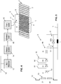
- the sensor 12 in the form of a dipole, an f / U converter (frequency-voltage converter) 13, a demodulator 14, a threshold value transmitter 15 and a low-pass filter 16 are connected downstream. About the latter, the trim element 11 is adjustable. Overall, the in Fig. 4 shown wiring of the trimming element 11 an interference frequency in a predetermined band and with an amplitude greater than an adjustable threshold.
- the corresponding parameters are based on conventional magnetic fields, as used in known MRI systems with a magnetic field strength of 1.5 T and 3 T.
- the sensor 12 can be arranged in the implant, wherein control lines lead to the frequency-dependent transmission device 3, but is preferable in 4 and 5 illustrated autarkic design, in which the sensor 12 is mounted in the region of the electrode device itself.
- Fig. 5 shows a concrete implementation of the in Fig. 4 Diagram shown circuit.
- the sensor 12 is a dipole, wherein the frequency / voltage (f / U) converter 13 is realized by a voltage divider of two impedances Z1 and Z2.
- the frequency / voltage (f / U) converter 13 is realized by a voltage divider of two impedances Z1 and Z2.
- tuned resonators for certain frequencies can control the corresponding bias voltage.
- Z1 would then be a resistor and Z2 would be an inductance.
- the demodulator 14 is represented by a diode D, which is followed by a threshold value transmitter 15 in the form of the diodes D1, D2 which can be bridged by switches S1, S2.
- the low-pass filter 16 is realized as an RC circuit with the resistor Rt and the capacitor Ct.
- the applied magnetic field corresponding DC voltage then controls the voltage-dependent capacitance C (U) of the resonant circuit 6 at. Its inductance L lies in the electrode feed line 1.
- the voltage-dependent capacitance C (U) may be a capacitance diode (tuning diode, varicap, varactor) or as in the EP 1 299 948 B1 be realized. Since in a design of the impedance Z1 as resistance and the impedance Z2 as inductance, the DC voltage U increases at the frequency f, the capacitance C (U) must be realized so that the capacitance C becomes smaller with increasing control voltage U, so that the effective frequency of Locking device is increased. In the opposite case, the impedance Z2 would have to be chosen as the resistance and the impedance Z1 as the inductance.
- the characteristic curve of the voltage-dependent capacitance C (U) is realized in such a way that the effective frequency follows the frequency f detected by the field sensor 12.
- the frequency / voltage converter 13 may be formed with a correspondingly compensative characteristic.
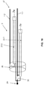
- the frequency-dependent transmission device 3 is integrated into a so-called fixing helix 17, which represents the distal end of an electrode device designed, for example, as a pacemaker electrode.
- the supply line 1 merges into a housing projection 18, on which the proximal-side turns of the fixing helix 17 are fastened.
- the subsequent to the attachment section 4 is analog Fig. 1 again designed as an inductance L with a good conductive coating 5 of the helical turns.
- the schematically indicated capacitor 7 with its capacitance C can be accommodated in the inner lumen 19 of the section 4 of the fixing helix 17, for example in the housing projection 18. Its housing thus forms the shoulder 20 to which the supply line 1 is attached.
- an electrical connection 21 is provided.
- the distal end of the Fixierhelix 17 is provided with axially expanded turns, which can be "screwed” by a rotation of the Fixierhelix about its longitudinal axis in the body tissue.
- the portion 4 of the fixing helix 17 forming the inductance L is insulated toward the outside in the areas where it can come into tissue contact. The contacting of the supply line 1 and the electrical connection 21 in the region of the shoulder takes place by crimping.
- Fig. 7 is a first circuit realization of the frequency-dependent transmission device 3 at two leads 1.1, 1.2 shown, the resistors, inductors, capacitors and transformers used. Implemented is an elliptical low-pass higher order, wherein serially connected in series parallel circuits of inductors La, Lb, Lc and capacitances Ca, Cb, Cc are switched into the supply line 1.1. A coupling to the supply line 1.2 via capacitors C1, C2, C3, C4 end and between the LC circuits.
- the supply line 1.1. supplies a contact pole of the electrode device, while the second lead 1.2 leads to a further contact pole, such as a ring electrode pole or an ICD shock coil. If no such other pole is present, the lead 1.2 can also lead to a potential reference pole, which is realized only for this purpose as a contact to the tissue, but otherwise has no further function for diagnosis or therapy.
- the potential reference pole is designated G (ground).
- Fig. 8 shows by way of example the frequency response of a frequency-dependent transmission device between 10 and 100 MHz. Recognizable takes place until shortly before the cutoff frequency of 100 MHz, no relevant attenuation, which then increases with a sharp edge to an attenuation of> 10 dB.
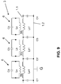
- Fig. 9 shows a frequency-dependent transmission device 3 with oscillating circuits 6 in the form of LC resonators, which are inductively coupled with their inductances La, Lb, Lc via Einkoppelinduktterrorismen La1, Lb1, Lc1 in the supply line 1.1.
- the execution corresponds to Fig. 9 the of Fig. 7 so that reference can be made to the description there.
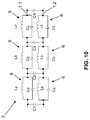
- a frequency-dependent transmission device 3 is shown, which is realized in two leads 1.1, 1.2 to non-illustrated contact poles.
- each supply line 1.1, 1.2 three oscillating circuits 6 are each connected in series with inductance La, Lb, Lc and capacitors Ca, Cb, Cc connected in parallel thereto.
- the two supply lines 1.1, 1.2 are also capacitive over capacitors C1, C2, C3, C4 end and between the resonant circuits coupled. In this embodiment symmetrically balanced low pass filter characteristics are achieved.
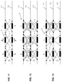
- Fig. 11 is a frequency-dependent transmission device 3 for two leads 1.1, 1.2 shown, in which in each case serially in the leads 1.1, 1.2 inductors L are turned on. The leads 1.1, 1.2 are then cross-referenced relative to the respective inductors L capacitively coupled by the capacitors 7 with the capacitance C.
- the purpose of this interconnection is to largely extinguish voltages caused in the inductors by electromagnetic alternating field. This is based on the fact that the two supply lines 1.1, 1.2 experience a substantially equal, tangential E field strength, since they are geometrically close to each other.
- the voltages caused in the inductors L overlap in antiphase due to the crossed coupling by the capacitors 7, whereby an extinction occurs.
- FIGS. 12 and 13 An analogous crosstalk of inductances in three Zu meeting 1.1, 1.2, 1.3 show the FIGS. 12 and 13 , While in Fig. 12 all cross-combinations are coupled by capacitors 7 are in the embodiment according to Fig. 13 omitted some coupling capacitors, which leads to no significant impairment of the voltage cancellation.
- Frequency-dependent transmission devices 3 are shown, which are based on the principle of waveguides. Like from the 15 to 17 becomes clear, these waveguides 23 consist of two adjacent conductors 24, 25, which are coupled via a dielectric 26. The waveguide 23 is thus characterized by a specific wave impedance Z0. Depending on the terminating impedance Za, which connects the two conductors 24, 25 of the waveguide 23, then an impedance Z is established at the opposite end between these conductors 24, 25.
- the termination impedance Za can be realized for example by a circuit of resistors R, inductors L, capacitors C and transmitters Ü.
- the components are to be dimensioned such that, given a length l of the waveguide 23, the desired impedance Z is established at the other end.
- Za and l In order to realize a filtering at a certain frequency, so for example a lock, Za and l must be designed so that Z ideally a severed line simulated. Then there is the case of a frequency-dependent line break. In the simplest, preferred case Za is a short circuit, then the low-frequency therapy and diagnostic currents can flow undisturbed.
- the length is determined in accordance with the specific wave impedance Z0, for which purpose a so-called "Smith Chart" is used.
- the procedure is reversed in exactly the opposite way.
- the termination Za remains open, over the length l of the waveguide 23, the impedance is then transformed so that at the corresponding frequency at the other end, a frequency-dependent short circuit occurs. For low-frequency currents, this short circuit does not exist, so that therapy and diagnosis are not impaired.
- the waveguide is cylindrical, wherein a coaxial inner conductor 24 and a tubular outer conductor 25 are coupled through the dielectric 26.
- Fig. 16 are planar, elongated conductors 24, 25 sandwiched and placed in between the dielectric 26th
- Fig. 17 For example, two wire-shaped conductors 24, 25 are positioned in a bar-shaped block of dielectric 26.
- FIG Fig. 18 A circuit realization of a frequency-dependent transmission device in an electrode device with two supply lines 1.1, 1.2 using waveguides 23.1, 23.2 is shown in FIG Fig. 18 shown.
- the distal end of an electrode device in the form of a heart electrode 27 is shown, which has a ring contact pole 28 and a tip pole 29.
- the feed line 1.1 the first waveguide 23.1 is turned on
- the feed line 1.2 supplies the ring contact pole 28.
- the second waveguide 23.2 is turned on.
- a frequency-dependent line interruption (current block) is realized on the supply line 1.1.
- a frequency-dependent short circuit is caused by means of the waveguide.
- the supply line 1.2 can also have a waveguide installed, as is the case with the supply line 1.1. Then, an interruption point is realized shortly before the ring contact pole 28.
- ring contact pole 28 and tip contact 29 corresponds to the embodiment according to Fig. 18 .
- two waveguides 23.1, 23.2 coupled in a consistent manner in the supply line 1.1 or line connection 30.
- the frequency-dependent transmission device 3 formed can be used simultaneously for operation at a plurality of frequencies.
- the networks 31 interposed in the waveguides 23 are each active for a given MRI frequency, so that a patient with a network as in FIG Fig. 19 implanted cardiac electrode in common MRI systems with 1.5 T, 3 T and 7 T magnetic field strength without problems remain.
- Fig. 20 combined with Fig. 21 visualizes the interposition of the networks 31 in the conductors 24, 25 of the waveguide 23.
- the conductors 24, 25 interrupted, at their connection points 32 are in Fig. 21a to l network implementations shown connectable.
- various short-circuit and interruption variants Fig. 21b, f, i and l
- various combinations of intermediate parallel LC resonant circuits Fig. 21, a, c, e and j
- serial LC-links Fig. 21, d, g, h and k
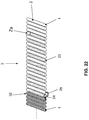
- Fig. 22 shows a waveguide variant of the frequency-dependent transmission device 3, in which over a certain length of the feed line 1, a coiled waveguide 23 is used with the same diameter and the same helix pitch.
- the "helical thread" is quasi two-start and alternately through the helices of the supply line 1 and the waveguide 23 is formed.
- the conductors 24, 25 are connected to the lead-away or away-carrying portion of the feed line 1.
- the waveguide termination Za at the proximal end of the waveguide 23 is shown.
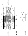
- FIGS. 23 to 26 show more complex implementations of electrode devices 27 with frequency dependent transmitters 3. So shows Fig. 23 a cardiac electrode 27 with a coiled outer conductor as a feed line 1.1 to a ring contact pole 28. In this outer conductor runs an inner conductor as a feed line 1.2 beyond the distal end of the feed line 1.1 and includes, for example, a (not shown) tip electrode electrically.
- the outer feed line 1.1 is designed at its end via a section 4 as inductance L by a correspondingly highly conductive coating 5.
- a section 4 is analogous Fig. 3 positioned a cylinder condenser 7 with inner sleeve 8, dielectric 9 and outer sleeve 10, which lies within the ring contact pole 28.
- the latter is electrically connected to the inner sleeve 8 of the capacitor 7, which in turn is connected to the distal end of the inductance L.
- Its proximal end is electrically connected to the outer sleeve 10, so that between supply line 1.1 and ring contact pole 28 is a parallel connection of the inductance L and the capacitance C of the capacitor 7.
- An analog frequency-dependent transmission device 3 is arranged offset in the outer conductor in the region of the inner feed line 1.2 distal to the transmission device 3. Again, an inductance L is in turn applied in the manner described within the coiled feed line 1.2, which is electrically connected at their end-facing end spirals with the outer and inner sleeve of the cylinder capacitor 7.
- a frequency-dependent transmission device 3 in the form of a frequency-dependent current blocking along the inner lead 1.2 of a heart electrode with high-pass behavior between the outer lead 1.1 and the inner lead 1.2 again.
- This pitch sensor 33 is designed in the form of an internal thread, in which the portion 4 of the inner feed line 1.2 designed as an inductance L is rotatable and thus displaceably mounted in a rotation in the axial direction.
- the last threads 34, 35 of the pitch sensor 33 which are each in the distal or proximal direction, are each designed to be electrically conductive and make contact with the turn of the coil forming the inductance L therein.
- the distally located thread 34 is electrically connected to the inner sleeve 8 of a cylindrical capacitor 7 arranged around the inductance L, the proximal thread 35 to the corresponding outer sleeve 10.
- the capacitor C formed by the dielectric 9 between the two sleeves 8, 10 is therewith connected in parallel to the inductance L between the two threads 34, 35 in the feed line 1.2 to the tip contact pole 29, as shown in the equivalent circuit diagram Fig. 24B becomes clear.
- Fig. 25 illustrated embodiment is different from the Fig. 24 only in that the energy absorbed by the electrode line meets different electronic components.
- the energy comes in the considered case from the proximal end and meets in the Fig. 25 first on a voltage divider while in Fig. 24 the energy first hits the bypass capacitor and residual energy is damped by the serially lying oscillating cone (blocking circuit).
- Fig. 26 shows a detail of an electrode device in which for the coiled inner lead 1.2 with an integrated pitch sensor 33, a low pass for the inner lead 1.2 is realized.
- an inductance L is again applied via a section 4 through a highly conductive coating or the like in the coiled feed line 1.2.
- the respective last helical turns of the inductance L in the proximal or distal direction are on the one hand connected to the inner sleeve 8 or outer sleeve 9 of a cylindrical capacitor 7, which is analogous Fig. 3 is constructed, electrically connected, so that in turn a parallel connection of the elements L and C is obtained (s. Fig. 26b) ,
- a ring contact pole 28 is placed, which is connected via the outer coiled feed line 1.1 to the implant.
- a pitch sensor 33 in the form of threads is formed, which is capacitively coupled to the outer sleeve 10 of the cylindrical capacitor 7 via a dielectric 36.
- annular sleeve 37 connected electrically to the inner sleeve of the cylindrical capacitor 7 is arranged distally in front of the cylindrical capacitor 7 within the ring contact pole 28, which in turn is capacitively coupled to the capacitor C1 via a dielectric 38 to the ring contact pole 28.
- the two leads 1.1, 1.2 are also capacitively coupled distally of the LC resonant circuit via the capacitor C1 (s. Fig. 26b) , ⁇ B> LIST OF REFERENCES ⁇ / b> 1 Supply line Fig.
Landscapes
- Health & Medical Sciences (AREA)
- Radiology & Medical Imaging (AREA)
- Animal Behavior & Ethology (AREA)
- Engineering & Computer Science (AREA)
- Biomedical Technology (AREA)
- Nuclear Medicine, Radiotherapy & Molecular Imaging (AREA)
- Veterinary Medicine (AREA)
- Life Sciences & Earth Sciences (AREA)
- Heart & Thoracic Surgery (AREA)
- General Health & Medical Sciences (AREA)
- Public Health (AREA)
- Cardiology (AREA)
- Electrotherapy Devices (AREA)
- Prostheses (AREA)
- Neurology (AREA)
Claims (15)
- Dispositif d'électrodes pour la commande de courant ou de tension entre un appareil électromédical implantable et un lieu de thérapie et/ou de diagnostic dans le corps humain, comprenant au moins une ligne d'alimentation (1) conduisant le courant / la tension et au moins un pôle de contact électrique vers une partie du corps, où au moins un équipement (3) avec des caractéristiques de transmission dépendant de la fréquence est associé à la ligne d'alimentation (1), où cet au moins un équipement de transmission (3) dépendant de la fréquence est formé par un ou plusieurs segments (4) de la ligne d'alimentation (1) conduisant le courant / la tension elle-même et où cet au moins un équipement de transmission (3) dépendant de la fréquence filtre au moins partiellement les signaux thérapeutiques et/ou diagnostiques non souhaités dans au moins une zone de fréquences définie, caractérisé en ce que l'équipement de transmission (3) dépendant de la fréquence est formé par un segment (4) hautement conducteur d'une hélice (2) de la ligne d'alimentation conduisant le courant / la tension.
- Dispositif d'électrodes selon la revendication 1, caractérisé en ce que les caractéristiques de transmission dépendant de la fréquence correspondent à celles d'un filtre passe-bas, d'un filtre coupe-bande ou d'un filtre passe-haut.
- Dispositif d'électrodes selon les revendications 1 ou 2, caractérisé en ce que l'équipement de transmission (3) dépendant de la fréquence présente un passage avec un diamètre minimal de préférence de 0,2 mm pour un guide-fil, un filguide, un mandrin ou similaire.
- Dispositif d'électrodes selon l'une des revendications 1 à 3, caractérisé en ce que le segment (4) hautement conducteur, présentant de préférence au moins une conductivité double par rapport à la conduite (1) conduisant le courant / la tension restante, est formé par un revêtement (5) hautement conducteur ou un dopage du segment (4) de l'hélice (2).
- Dispositif d'électrodes selon l'une des revendications 1 à 4, caractérisé en ce que le segment (4) hautement conducteur de l'hélice (2) est pourvu d'enroulements isolants.
- Dispositif d'électrodes selon l'une des revendications 1 à 5, caractérisé en ce que le segment (4) hautement conducteur de l'hélice (2) forme avec un condensateur (7) branché en parallèle un circuit résonnant inductance-capacité (6) servant d'équipement de transmission (3) dépendant de la fréquence, ou le segment (4) hautement conducteur de l'hélice (2) forme avec un condensateur (7) branché en parallèle un circuit résonnant inductance-capacité (6) servant d'équipement de transmission (3) dépendant de la fréquence, et le condensateur du circuit résonnant inductance-capacité (6) est formé par un condensateur cylindrique (7) disposé autour du segment (4) conducteur de l'hélice (2) et/ou à l'intérieur du segment (4) conducteur de l'hélice (2).
- Dispositif d'électrodes selon l'une des revendications précitées, caractérisé en ce que la dépendance vis-à-vis de la fréquence de l'équipement de transmission (3) dépendant de la fréquence peut être commandée de manière variable.
- Dispositif d'électrodes selon la revendication 7, caractérisé en ce que la commande de la dépendance de la fréquence est effectuée à l'aide d'un élément de calage (11), de préférence, un condensateur commandé en tension, ou par une tension de commande.
- Dispositif d'électrodes selon la revendication 8, caractérisé en ce que la tension de commande peut être générée par une programmation de l'appareil électromédical ou par un capteur (12) pour la détermination de signaux thérapeutiques et/ou diagnostiques non souhaités.
- Dispositif d'électrodes selon la revendication 9, caractérisé en ce que le capteur (12) est disposé dans l'appareil électromédical implanté ou est adjoint à la ligne d'alimentation (1).
- Dispositif d'électrodes selon la revendication 10, caractérisé en ce que le capteur est un capteur de champ (12) pour des champs électriques, magnétiques et/ou électromagnétiques, est notamment un dipôle, où les champs sont des champs statiques et/ou alternatifs.
- Dispositif d'électrodes selon l'une des revendications précitées, caractérisé en ce que l'équipement de transmission (3) dépendant de la fréquence est formé par un ou plusieurs circuits oscillants (LC), où chaque circuit oscillant (LC) est couplé de manière inductive.
- Dispositif d'électrodes selon l'une des revendications précitées, caractérisé en ce que l'équipement de transmission (3) dépendant de la fréquence est formé sur une hélice de fixation (17) sur le dispositif d'électrodes.
- Dispositif d'électrodes selon l'une des revendications précitées, caractérisé en ce que l'équipement de transmission (3) dépendant de la fréquence est formé par au moins un guide d'ondes (23) avec une impédance d'onde spécifique à la fréquence.
- Dispositif d'électrodes au moins selon la revendication 14, caractérisé en ce que l'au moins un guide d'ondes (23) est terminé par une impédance de terminaison (Za) et/ou, pour l'adaptation de la fréquence à au moins deux fréquences de signal non souhaitées dans l'au moins un guide d'ondes (23), est branché entre au moins deux réseaux (31), et/ou un réseau (31) termine le guide d'ondes (23), et/ou le guide d'ondes (23) est formé par deux conducteurs (24, 25) couplés par l'intermédiaire d'un diélectrique (26), et/ou le guide d'ondes (23) est en hélice et est intégré dans une ligne d'alimentation (1) conduisant le courant / la tension conçue sous forme d'une conduite hélicoïdale.
Applications Claiming Priority (1)
| Application Number | Priority Date | Filing Date | Title |
|---|---|---|---|
| DE102010000373 | 2010-02-11 |
Publications (2)
| Publication Number | Publication Date |
|---|---|
| EP2359896A1 EP2359896A1 (fr) | 2011-08-24 |
| EP2359896B1 true EP2359896B1 (fr) | 2016-01-27 |
Family
ID=43898181
Family Applications (2)
| Application Number | Title | Priority Date | Filing Date |
|---|---|---|---|
| EP11153009.3A Not-in-force EP2359896B1 (fr) | 2010-02-11 | 2011-02-02 | Dispositif d'électrodes pour la commande de courant ou de tension entre un appareil électromédical implantable et un lieu de thérapie et/ou diagnostic dans le corps humain |
| EP11153010A Withdrawn EP2359898A3 (fr) | 2010-02-11 | 2011-02-02 | Élément implantable avec des moyens pour réduire une densité de flux |
Family Applications After (1)
| Application Number | Title | Priority Date | Filing Date |
|---|---|---|---|
| EP11153010A Withdrawn EP2359898A3 (fr) | 2010-02-11 | 2011-02-02 | Élément implantable avec des moyens pour réduire une densité de flux |
Country Status (2)
| Country | Link |
|---|---|
| US (2) | US8818509B2 (fr) |
| EP (2) | EP2359896B1 (fr) |
Families Citing this family (21)
| Publication number | Priority date | Publication date | Assignee | Title |
|---|---|---|---|---|
| US9295828B2 (en) * | 2001-04-13 | 2016-03-29 | Greatbatch Ltd. | Self-resonant inductor wound portion of an implantable lead for enhanced MRI compatibility of active implantable medical devices |
| US8401212B2 (en) | 2007-10-12 | 2013-03-19 | Earlens Corporation | Multifunction system and method for integrated hearing and communication with noise cancellation and feedback management |
| WO2009155358A1 (fr) | 2008-06-17 | 2009-12-23 | Earlens Corporation | Dispositifs d’audition électromécaniques optiques dotés de composants d’alimentation et de signal séparés |
| EP3509324B1 (fr) | 2008-09-22 | 2023-08-16 | Earlens Corporation | Dispositifs à armature équilibrée et procédés d'écoute |
| US8996126B2 (en) | 2009-02-04 | 2015-03-31 | Greatbatch Ltd. | Composite RF current attenuator for a medical lead |
| US8942825B2 (en) | 2010-12-17 | 2015-01-27 | Biotronik Se & Co. Kg | Implantable device with elongated electrical conductor |
| US8509915B2 (en) * | 2010-12-17 | 2013-08-13 | Biotronik Se & Co. Kg | Implantable electrode line device for reducing undesirable effects of electromagnetic fields |
| EP3758394A1 (fr) | 2010-12-20 | 2020-12-30 | Earlens Corporation | Appareil auditif intra-auriculaire anatomiquement personnalisé |
| EP2594314A1 (fr) * | 2011-11-17 | 2013-05-22 | Greatbatch Ltd. | Atténuateur RF composite pour une dérivation médicale |
| US10034103B2 (en) | 2014-03-18 | 2018-07-24 | Earlens Corporation | High fidelity and reduced feedback contact hearing apparatus and methods |
| DK3169396T3 (da) | 2014-07-14 | 2021-06-28 | Earlens Corp | Glidende forspænding og peak-begrænsning for optiske høreapparater |
| US9924276B2 (en) | 2014-11-26 | 2018-03-20 | Earlens Corporation | Adjustable venting for hearing instruments |
| DK3888564T3 (da) | 2015-10-02 | 2025-07-14 | Earlens Corp | Indretning til tilpasset afgivelse af medicin i øregangen |
| US11350226B2 (en) | 2015-12-30 | 2022-05-31 | Earlens Corporation | Charging protocol for rechargeable hearing systems |
| WO2017116791A1 (fr) | 2015-12-30 | 2017-07-06 | Earlens Corporation | Systèmes, appareil et procédés auditifs reposant sur la lumière |
| CN112738700A (zh) | 2016-09-09 | 2021-04-30 | 伊尔兰斯公司 | 智能镜系统和方法 |
| WO2018093733A1 (fr) | 2016-11-15 | 2018-05-24 | Earlens Corporation | Procédure d'impression améliorée |
| WO2019173470A1 (fr) | 2018-03-07 | 2019-09-12 | Earlens Corporation | Dispositif auditif de contact et matériaux de structure de rétention |
| WO2019199680A1 (fr) | 2018-04-09 | 2019-10-17 | Earlens Corporation | Filtre dynamique |
| EP3831095A4 (fr) * | 2018-07-31 | 2022-06-08 | Earlens Corporation | Couplage inductif en champ proche dans un système auditif à contact |
| CN111355360B (zh) * | 2020-04-08 | 2021-06-08 | 江西源能电气技术有限公司 | 一种电流型阻抗源交流的变频器 |
Family Cites Families (18)
| Publication number | Priority date | Publication date | Assignee | Title |
|---|---|---|---|---|
| US5651767A (en) * | 1994-05-06 | 1997-07-29 | Alfred F. Mann Foundation For Scientific Research | Replaceable catheter system for physiological sensors, stimulating electrodes and/or implantable fluid delivery systems |
| US8244370B2 (en) * | 2001-04-13 | 2012-08-14 | Greatbatch Ltd. | Band stop filter employing a capacitor and an inductor tank circuit to enhance MRI compatibility of active medical devices |
| DE10021867A1 (de) | 2000-05-05 | 2001-11-15 | Infineon Technologies Ag | Spannungsgesteuerte Kapazität |
| US6949929B2 (en) * | 2003-06-24 | 2005-09-27 | Biophan Technologies, Inc. | Magnetic resonance imaging interference immune device |
| US7877150B2 (en) * | 2004-03-30 | 2011-01-25 | Medtronic, Inc. | Lead electrode for use in an MRI-safe implantable medical device |
| US8055351B2 (en) * | 2005-10-21 | 2011-11-08 | Boston Scientific Neuromodulation Corporation | MRI-safe high impedance lead systems |
| US8233985B2 (en) * | 2005-11-04 | 2012-07-31 | Kenergy, Inc. | MRI compatible implanted electronic medical device with power and data communication capability |
| US9037257B2 (en) * | 2006-04-07 | 2015-05-19 | Medtronic, Inc. | Resonance tuning module for implantable devices and leads |
| US8116862B2 (en) * | 2006-06-08 | 2012-02-14 | Greatbatch Ltd. | Tank filters placed in series with the lead wires or circuits of active medical devices to enhance MRI compatibility |
| US7702387B2 (en) | 2006-06-08 | 2010-04-20 | Greatbatch Ltd. | Tank filters adaptable for placement with a guide wire, in series with the lead wires or circuits of active medical devices to enhance MRI compatibility |
| US7610101B2 (en) * | 2006-11-30 | 2009-10-27 | Cardiac Pacemakers, Inc. | RF rejecting lead |
| US8768486B2 (en) * | 2006-12-11 | 2014-07-01 | Medtronic, Inc. | Medical leads with frequency independent magnetic resonance imaging protection |
| US8219207B2 (en) * | 2007-03-08 | 2012-07-10 | Medtronic, Inc. | Thermal switch for implantable medical devices |
| US20090099555A1 (en) * | 2007-10-11 | 2009-04-16 | Ingmar Viohl | Reduction of rf induced tissue heating using conductive surface pattern |
| US20090099440A1 (en) | 2007-10-11 | 2009-04-16 | Ingmar Viohl | Reduction of rf induced tissue heating using discrete winding patterns |
| WO2009100003A1 (fr) * | 2008-02-06 | 2009-08-13 | Cardiac Pacemakers, Inc. | Dérivation avec caractéristiques de conception compatibles avec une imagerie par résonance magnétique |
| US20090270956A1 (en) * | 2008-04-25 | 2009-10-29 | Pacesetter, Inc. | Implantable medical lead configured for improved mri safety |
| US9399129B2 (en) * | 2008-10-30 | 2016-07-26 | Pacesetter, Inc. | MRI compatible implantable medical lead and method of making same |
-
2011
- 2011-01-14 US US13/006,501 patent/US8818509B2/en not_active Expired - Fee Related
- 2011-01-31 US US13/017,915 patent/US8346371B2/en not_active Expired - Fee Related
- 2011-02-02 EP EP11153009.3A patent/EP2359896B1/fr not_active Not-in-force
- 2011-02-02 EP EP11153010A patent/EP2359898A3/fr not_active Withdrawn
Also Published As
| Publication number | Publication date |
|---|---|
| US20110196460A1 (en) | 2011-08-11 |
| US20110196461A1 (en) | 2011-08-11 |
| EP2359898A2 (fr) | 2011-08-24 |
| US8346371B2 (en) | 2013-01-01 |
| EP2359898A3 (fr) | 2012-02-08 |
| US8818509B2 (en) | 2014-08-26 |
| EP2359896A1 (fr) | 2011-08-24 |
Similar Documents
| Publication | Publication Date | Title |
|---|---|---|
| EP2359896B1 (fr) | Dispositif d'électrodes pour la commande de courant ou de tension entre un appareil électromédical implantable et un lieu de thérapie et/ou diagnostic dans le corps humain | |
| EP1923094B1 (fr) | Cathéter à électrode destiné à des interventions | |
| EP1923095B1 (fr) | Electrode destinée à des interventions | |
| US20090099555A1 (en) | Reduction of rf induced tissue heating using conductive surface pattern | |
| WO2009049310A1 (fr) | Réduction du chauffage des tissus induit par rf en utilisant des modèles de surface conductrice | |
| EP2465572B1 (fr) | Fil implantable compatible avec l'IRM | |
| EP3756725A1 (fr) | Conduite d'électrode pouvant être implantée pourvue de conducteur raccordé à un treillis | |
| EP2359895B1 (fr) | Sonde d'adaptation pour l'introduction d'implants médicaux actifs dans des dispositifs d'électrodes implantées et ensemble comprenant un dispositif d'électrodes implantables et une sonde d'adaptation | |
| DE102020100121A1 (de) | Implantierbare Elektrode mit einer Stichleitung | |
| EP2359894A1 (fr) | Electrode dotée d'un filtre HF pour implants médicaux actifs | |
| EP3269423A1 (fr) | Appareil medical implantable comprenant une antenne pour la communication sans fil | |
| EP2985053A1 (fr) | Ligne électrique implantable | |
| EP2359899B1 (fr) | Dispositif d'électrodes pour implants médicaux actifs | |
| EP2465569B1 (fr) | Appareil implantable | |
| EP2446922B1 (fr) | Conducteurs implantables avec des conducteurs supplémentaires pour le découplage de champs | |
| EP2848282B1 (fr) | Appareil implantable | |
| EP2465573B1 (fr) | Appareil implantable | |
| EP2985054B1 (fr) | Appareil implantable doté d'un filtre électrique | |
| EP2380489A1 (fr) | Dispositif de dérivation et système de cathéter protégé contre les IRM | |
| EP2853288B1 (fr) | Appareil implantable et procédé de fabrication d'un appareil implantable | |
| EP2848281B1 (fr) | Dispositif d'électrodes pour un implant médical et implant médical doté d'un dispositif d'électrodes | |
| EP2465570B1 (fr) | Appareil implantable | |
| EP2457613A1 (fr) | Conduite implantable dotée d'un corps de conduite allongé longitudinalement | |
| DE102019106675A1 (de) | Leitung für ein medizinisches Implantat, mit integrierten periodischen Induktionsspulen (iPIC) für verringerte Wechselwirkungen mit elektromagnetischen Feldern | |
| EP2522387B1 (fr) | Ligne médicale implantable |
Legal Events
| Date | Code | Title | Description |
|---|---|---|---|
| PUAI | Public reference made under article 153(3) epc to a published international application that has entered the european phase |
Free format text: ORIGINAL CODE: 0009012 |
|
| PUAI | Public reference made under article 153(3) epc to a published international application that has entered the european phase |
Free format text: ORIGINAL CODE: 0009012 |
|
| AK | Designated contracting states |
Kind code of ref document: A1 Designated state(s): AL AT BE BG CH CY CZ DE DK EE ES FI FR GB GR HR HU IE IS IT LI LT LU LV MC MK MT NL NO PL PT RO RS SE SI SK SM TR |
|
| AX | Request for extension of the european patent |
Extension state: BA ME |
|
| 17P | Request for examination filed |
Effective date: 20120206 |
|
| 17Q | First examination report despatched |
Effective date: 20150210 |
|
| REG | Reference to a national code |
Ref country code: DE Ref legal event code: R079 Ref document number: 502011008758 Country of ref document: DE Free format text: PREVIOUS MAIN CLASS: A61N0001080000 Ipc: A61N0001050000 |
|
| RIC1 | Information provided on ipc code assigned before grant |
Ipc: A61N 1/08 20060101ALI20150707BHEP Ipc: A61N 1/05 20060101AFI20150707BHEP |
|
| GRAP | Despatch of communication of intention to grant a patent |
Free format text: ORIGINAL CODE: EPIDOSNIGR1 |
|
| INTG | Intention to grant announced |
Effective date: 20150821 |
|
| GRAP | Despatch of communication of intention to grant a patent |
Free format text: ORIGINAL CODE: EPIDOSNIGR1 |
|
| INTG | Intention to grant announced |
Effective date: 20150921 |
|
| GRAS | Grant fee paid |
Free format text: ORIGINAL CODE: EPIDOSNIGR3 |
|
| GRAA | (expected) grant |
Free format text: ORIGINAL CODE: 0009210 |
|
| AK | Designated contracting states |
Kind code of ref document: B1 Designated state(s): AL AT BE BG CH CY CZ DE DK EE ES FI FR GB GR HR HU IE IS IT LI LT LU LV MC MK MT NL NO PL PT RO RS SE SI SK SM TR |
|
| REG | Reference to a national code |
Ref country code: GB Ref legal event code: FG4D Free format text: NOT ENGLISH |
|
| REG | Reference to a national code |
Ref country code: CH Ref legal event code: EP |
|
| REG | Reference to a national code |
Ref country code: AT Ref legal event code: REF Ref document number: 772407 Country of ref document: AT Kind code of ref document: T Effective date: 20160215 |
|
| REG | Reference to a national code |
Ref country code: IE Ref legal event code: FG4D Free format text: LANGUAGE OF EP DOCUMENT: GERMAN |
|
| REG | Reference to a national code |
Ref country code: DE Ref legal event code: R096 Ref document number: 502011008758 Country of ref document: DE |
|
| REG | Reference to a national code |
Ref country code: LT Ref legal event code: MG4D |
|
| PG25 | Lapsed in a contracting state [announced via postgrant information from national office to epo] |
Ref country code: BE Free format text: LAPSE BECAUSE OF NON-PAYMENT OF DUE FEES Effective date: 20160229 |
|
| REG | Reference to a national code |
Ref country code: NL Ref legal event code: MP Effective date: 20160127 |
|
| PG25 | Lapsed in a contracting state [announced via postgrant information from national office to epo] |
Ref country code: NL Free format text: LAPSE BECAUSE OF FAILURE TO SUBMIT A TRANSLATION OF THE DESCRIPTION OR TO PAY THE FEE WITHIN THE PRESCRIBED TIME-LIMIT Effective date: 20160127 |
|
| PG25 | Lapsed in a contracting state [announced via postgrant information from national office to epo] |
Ref country code: ES Free format text: LAPSE BECAUSE OF FAILURE TO SUBMIT A TRANSLATION OF THE DESCRIPTION OR TO PAY THE FEE WITHIN THE PRESCRIBED TIME-LIMIT Effective date: 20160127 Ref country code: NO Free format text: LAPSE BECAUSE OF FAILURE TO SUBMIT A TRANSLATION OF THE DESCRIPTION OR TO PAY THE FEE WITHIN THE PRESCRIBED TIME-LIMIT Effective date: 20160427 Ref country code: FI Free format text: LAPSE BECAUSE OF FAILURE TO SUBMIT A TRANSLATION OF THE DESCRIPTION OR TO PAY THE FEE WITHIN THE PRESCRIBED TIME-LIMIT Effective date: 20160127 Ref country code: HR Free format text: LAPSE BECAUSE OF FAILURE TO SUBMIT A TRANSLATION OF THE DESCRIPTION OR TO PAY THE FEE WITHIN THE PRESCRIBED TIME-LIMIT Effective date: 20160127 Ref country code: IT Free format text: LAPSE BECAUSE OF FAILURE TO SUBMIT A TRANSLATION OF THE DESCRIPTION OR TO PAY THE FEE WITHIN THE PRESCRIBED TIME-LIMIT Effective date: 20160127 Ref country code: GR Free format text: LAPSE BECAUSE OF FAILURE TO SUBMIT A TRANSLATION OF THE DESCRIPTION OR TO PAY THE FEE WITHIN THE PRESCRIBED TIME-LIMIT Effective date: 20160428 |
|
| PG25 | Lapsed in a contracting state [announced via postgrant information from national office to epo] |
Ref country code: LV Free format text: LAPSE BECAUSE OF FAILURE TO SUBMIT A TRANSLATION OF THE DESCRIPTION OR TO PAY THE FEE WITHIN THE PRESCRIBED TIME-LIMIT Effective date: 20160127 Ref country code: LT Free format text: LAPSE BECAUSE OF FAILURE TO SUBMIT A TRANSLATION OF THE DESCRIPTION OR TO PAY THE FEE WITHIN THE PRESCRIBED TIME-LIMIT Effective date: 20160127 Ref country code: IS Free format text: LAPSE BECAUSE OF FAILURE TO SUBMIT A TRANSLATION OF THE DESCRIPTION OR TO PAY THE FEE WITHIN THE PRESCRIBED TIME-LIMIT Effective date: 20160527 Ref country code: RS Free format text: LAPSE BECAUSE OF FAILURE TO SUBMIT A TRANSLATION OF THE DESCRIPTION OR TO PAY THE FEE WITHIN THE PRESCRIBED TIME-LIMIT Effective date: 20160127 Ref country code: PT Free format text: LAPSE BECAUSE OF FAILURE TO SUBMIT A TRANSLATION OF THE DESCRIPTION OR TO PAY THE FEE WITHIN THE PRESCRIBED TIME-LIMIT Effective date: 20160527 Ref country code: SE Free format text: LAPSE BECAUSE OF FAILURE TO SUBMIT A TRANSLATION OF THE DESCRIPTION OR TO PAY THE FEE WITHIN THE PRESCRIBED TIME-LIMIT Effective date: 20160127 Ref country code: PL Free format text: LAPSE BECAUSE OF FAILURE TO SUBMIT A TRANSLATION OF THE DESCRIPTION OR TO PAY THE FEE WITHIN THE PRESCRIBED TIME-LIMIT Effective date: 20160127 |
|
| REG | Reference to a national code |
Ref country code: DE Ref legal event code: R097 Ref document number: 502011008758 Country of ref document: DE |
|
| PG25 | Lapsed in a contracting state [announced via postgrant information from national office to epo] |
Ref country code: EE Free format text: LAPSE BECAUSE OF FAILURE TO SUBMIT A TRANSLATION OF THE DESCRIPTION OR TO PAY THE FEE WITHIN THE PRESCRIBED TIME-LIMIT Effective date: 20160127 Ref country code: DK Free format text: LAPSE BECAUSE OF FAILURE TO SUBMIT A TRANSLATION OF THE DESCRIPTION OR TO PAY THE FEE WITHIN THE PRESCRIBED TIME-LIMIT Effective date: 20160127 Ref country code: MC Free format text: LAPSE BECAUSE OF FAILURE TO SUBMIT A TRANSLATION OF THE DESCRIPTION OR TO PAY THE FEE WITHIN THE PRESCRIBED TIME-LIMIT Effective date: 20160127 |
|
| PG25 | Lapsed in a contracting state [announced via postgrant information from national office to epo] |
Ref country code: CZ Free format text: LAPSE BECAUSE OF FAILURE TO SUBMIT A TRANSLATION OF THE DESCRIPTION OR TO PAY THE FEE WITHIN THE PRESCRIBED TIME-LIMIT Effective date: 20160127 Ref country code: RO Free format text: LAPSE BECAUSE OF FAILURE TO SUBMIT A TRANSLATION OF THE DESCRIPTION OR TO PAY THE FEE WITHIN THE PRESCRIBED TIME-LIMIT Effective date: 20160127 Ref country code: SM Free format text: LAPSE BECAUSE OF FAILURE TO SUBMIT A TRANSLATION OF THE DESCRIPTION OR TO PAY THE FEE WITHIN THE PRESCRIBED TIME-LIMIT Effective date: 20160127 Ref country code: SK Free format text: LAPSE BECAUSE OF FAILURE TO SUBMIT A TRANSLATION OF THE DESCRIPTION OR TO PAY THE FEE WITHIN THE PRESCRIBED TIME-LIMIT Effective date: 20160127 |
|
| PLBE | No opposition filed within time limit |
Free format text: ORIGINAL CODE: 0009261 |
|
| STAA | Information on the status of an ep patent application or granted ep patent |
Free format text: STATUS: NO OPPOSITION FILED WITHIN TIME LIMIT |
|
| GBPC | Gb: european patent ceased through non-payment of renewal fee |
Effective date: 20160427 |
|
| 26N | No opposition filed |
Effective date: 20161028 |
|
| PG25 | Lapsed in a contracting state [announced via postgrant information from national office to epo] |
Ref country code: GB Free format text: LAPSE BECAUSE OF NON-PAYMENT OF DUE FEES Effective date: 20160427 |
|
| REG | Reference to a national code |
Ref country code: FR Ref legal event code: ST Effective date: 20161230 |
|
| PG25 | Lapsed in a contracting state [announced via postgrant information from national office to epo] |
Ref country code: BG Free format text: LAPSE BECAUSE OF FAILURE TO SUBMIT A TRANSLATION OF THE DESCRIPTION OR TO PAY THE FEE WITHIN THE PRESCRIBED TIME-LIMIT Effective date: 20160427 Ref country code: SI Free format text: LAPSE BECAUSE OF FAILURE TO SUBMIT A TRANSLATION OF THE DESCRIPTION OR TO PAY THE FEE WITHIN THE PRESCRIBED TIME-LIMIT Effective date: 20160127 |
|
| REG | Reference to a national code |
Ref country code: AT Ref legal event code: MM01 Ref document number: 772407 Country of ref document: AT Kind code of ref document: T Effective date: 20160202 |
|
| PG25 | Lapsed in a contracting state [announced via postgrant information from national office to epo] |
Ref country code: FR Free format text: LAPSE BECAUSE OF NON-PAYMENT OF DUE FEES Effective date: 20160329 |
|
| PG25 | Lapsed in a contracting state [announced via postgrant information from national office to epo] |
Ref country code: AT Free format text: LAPSE BECAUSE OF NON-PAYMENT OF DUE FEES Effective date: 20160202 |
|
| PG25 | Lapsed in a contracting state [announced via postgrant information from national office to epo] |
Ref country code: MT Free format text: LAPSE BECAUSE OF FAILURE TO SUBMIT A TRANSLATION OF THE DESCRIPTION OR TO PAY THE FEE WITHIN THE PRESCRIBED TIME-LIMIT Effective date: 20160127 |
|
| PG25 | Lapsed in a contracting state [announced via postgrant information from national office to epo] |
Ref country code: HU Free format text: LAPSE BECAUSE OF FAILURE TO SUBMIT A TRANSLATION OF THE DESCRIPTION OR TO PAY THE FEE WITHIN THE PRESCRIBED TIME-LIMIT; INVALID AB INITIO Effective date: 20110202 Ref country code: CY Free format text: LAPSE BECAUSE OF FAILURE TO SUBMIT A TRANSLATION OF THE DESCRIPTION OR TO PAY THE FEE WITHIN THE PRESCRIBED TIME-LIMIT Effective date: 20160127 |
|
| PG25 | Lapsed in a contracting state [announced via postgrant information from national office to epo] |
Ref country code: LU Free format text: LAPSE BECAUSE OF NON-PAYMENT OF DUE FEES Effective date: 20160202 Ref country code: MK Free format text: LAPSE BECAUSE OF FAILURE TO SUBMIT A TRANSLATION OF THE DESCRIPTION OR TO PAY THE FEE WITHIN THE PRESCRIBED TIME-LIMIT Effective date: 20160127 Ref country code: TR Free format text: LAPSE BECAUSE OF FAILURE TO SUBMIT A TRANSLATION OF THE DESCRIPTION OR TO PAY THE FEE WITHIN THE PRESCRIBED TIME-LIMIT Effective date: 20160127 |
|
| PG25 | Lapsed in a contracting state [announced via postgrant information from national office to epo] |
Ref country code: AL Free format text: LAPSE BECAUSE OF FAILURE TO SUBMIT A TRANSLATION OF THE DESCRIPTION OR TO PAY THE FEE WITHIN THE PRESCRIBED TIME-LIMIT Effective date: 20160127 |
|
| PGFP | Annual fee paid to national office [announced via postgrant information from national office to epo] |
Ref country code: IE Payment date: 20220216 Year of fee payment: 12 Ref country code: DE Payment date: 20220222 Year of fee payment: 12 Ref country code: CH Payment date: 20220221 Year of fee payment: 12 |
|
| REG | Reference to a national code |
Ref country code: DE Ref legal event code: R119 Ref document number: 502011008758 Country of ref document: DE |
|
| REG | Reference to a national code |
Ref country code: CH Ref legal event code: PL |
|
| PG25 | Lapsed in a contracting state [announced via postgrant information from national office to epo] |
Ref country code: LI Free format text: LAPSE BECAUSE OF NON-PAYMENT OF DUE FEES Effective date: 20230228 Ref country code: CH Free format text: LAPSE BECAUSE OF NON-PAYMENT OF DUE FEES Effective date: 20230228 |
|
| REG | Reference to a national code |
Ref country code: IE Ref legal event code: MM4A |
|
| PG25 | Lapsed in a contracting state [announced via postgrant information from national office to epo] |
Ref country code: IE Free format text: LAPSE BECAUSE OF NON-PAYMENT OF DUE FEES Effective date: 20230202 Ref country code: DE Free format text: LAPSE BECAUSE OF NON-PAYMENT OF DUE FEES Effective date: 20230901 |