EP2359987B1 - Mobile Gelenkvorrichtung zum Überwinden von Hindernissen - Google Patents
Mobile Gelenkvorrichtung zum Überwinden von Hindernissen Download PDFInfo
- Publication number
- EP2359987B1 EP2359987B1 EP11305166.8A EP11305166A EP2359987B1 EP 2359987 B1 EP2359987 B1 EP 2359987B1 EP 11305166 A EP11305166 A EP 11305166A EP 2359987 B1 EP2359987 B1 EP 2359987B1
- Authority
- EP
- European Patent Office
- Prior art keywords
- module
- plane
- cables
- mid
- intermediate module
- Prior art date
- Legal status (The legal status is an assumption and is not a legal conclusion. Google has not performed a legal analysis and makes no representation as to the accuracy of the status listed.)
- Not-in-force
Links
Images


Classifications
-
- B—PERFORMING OPERATIONS; TRANSPORTING
- B25—HAND TOOLS; PORTABLE POWER-DRIVEN TOOLS; MANIPULATORS
- B25J—MANIPULATORS; CHAMBERS PROVIDED WITH MANIPULATION DEVICES
- B25J9/00—Program-controlled manipulators
- B25J9/06—Program-controlled manipulators characterised by multi-articulated arms
-
- B—PERFORMING OPERATIONS; TRANSPORTING
- B08—CLEANING
- B08B—CLEANING IN GENERAL; PREVENTION OF FOULING IN GENERAL
- B08B9/00—Cleaning hollow articles by methods or apparatus specially adapted thereto
- B08B9/02—Cleaning pipes or tubes or systems of pipes or tubes
- B08B9/027—Cleaning the internal surfaces; Removal of blockages
- B08B9/04—Cleaning the internal surfaces; Removal of blockages using cleaning devices introduced into and moved along the pipes
- B08B9/043—Cleaning the internal surfaces; Removal of blockages using cleaning devices introduced into and moved along the pipes moved by externally powered mechanical linkage, e.g. pushed or drawn through the pipes
- B08B9/045—Cleaning the internal surfaces; Removal of blockages using cleaning devices introduced into and moved along the pipes moved by externally powered mechanical linkage, e.g. pushed or drawn through the pipes the cleaning devices being rotated while moved, e.g. flexible rotating shaft or "snake"
-
- B—PERFORMING OPERATIONS; TRANSPORTING
- B25—HAND TOOLS; PORTABLE POWER-DRIVEN TOOLS; MANIPULATORS
- B25J—MANIPULATORS; CHAMBERS PROVIDED WITH MANIPULATION DEVICES
- B25J9/00—Program-controlled manipulators
- B25J9/06—Program-controlled manipulators characterised by multi-articulated arms
- B25J9/065—Snake robots
-
- B—PERFORMING OPERATIONS; TRANSPORTING
- B62—LAND VEHICLES FOR TRAVELLING OTHERWISE THAN ON RAILS
- B62D—MOTOR VEHICLES; TRAILERS
- B62D53/00—Tractor-trailer combinations; Road trains
- B62D53/005—Combinations with at least three axles and comprising two or more articulated parts
Definitions
- the present invention relates to an articulated device, mobile and capable of crossing, said device being mechanically controlled and equipped with an orientation transfer device between two joints each connecting two modules.
- the reconnaissance of enemy zones or the exploration of unknown and uneven grounds can prove to be perilous, said zones being able to be trapped or monitored and said grounds being able to conceal hidden dangers.
- This first device takes the form of a train comprising several articulated modules, said articulations being produced by springs, as well as means of securing by interlocking between said modules.
- cables are provided allowing the modules to be brought together so that they are joined together by interlocking, said cables stiffening and thus immobilizing the train of modules in the piping.
- this first articulated device does not include means making it possible to control the orientation of the various modules between them, the articulations between modules remain free as long as the cables are not pulled and the modules are guided by the curves of the inner wall of the piping.
- this first articulated device is intended to be moved by sliding it in a pipe, it does not include independent movement means fitted to each module.
- this second articulated device is composed of several modules interconnected by an articulated connection, and each module is equipped with displacement means with at least one caterpillar on each of its four faces.
- At least one caterpillar of each module is always in contact with the surface of said module. relief.
- This second articulated device is capable of moving both on the surface of a raised area and in a pipe.
- no means are provided for making it possible to precisely control the relative movements between modules.
- articulated devices are known, the different modules of which are driven by means of several electric servomotors, at least one servomotor for controlling each degree of freedom in rotation of a connection between two modules.
- Such an articulated device is for example disclosed in patents JP H04 28987 U .
- these servomotors increase the manufacturing cost of an articulated device, increase its weight relatively significantly, and they require reinforced protection under certain operating conditions. use of the articulated device as they can be damaged by water or dust infiltration.
- the present invention aims to overcome the drawbacks of the prior art by proposing an articulated device comprising several modules, the relative movements of which, and therefore the positions, are controlled by robust, light means and having a reduced cost compared to the means. known such as servomotors.
- the invention relates to an articulated device comprising at least three consecutive modules: a first module, or head module, at least one intermediate module, and a last module, or tail module, interconnected by at least two articulations, at least one module comprising displacement means and each intermediate module being connected by a first articulation to the previous module and by a second articulation to the next module, each articulation releasing at least one rotational movement in a first median plane of the device articulated around an axis perpendicular to said plane, and each articulation releasing a second rotational movement in a second median plane of the device articulated around a axis perpendicular to said second median plane, said second plane being substantially perpendicular to the first median plane, the articulated device being equipped with a device for mechanically controlling the relative movements of said modules, this device for mechanically controlling the relative movements of said modules comprising at least one mechanical steering device allowing at least a increase or reduce the steering angle between the first module and the last module in the first median plane, each first first module, or
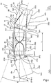
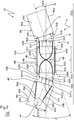
- the figure 1 schematically illustrates a top view in a first median plane PH of an articulated device 10 according to the invention.
- Said articulated device 10 comprises at least three consecutive M modules: a first module M1, or head module, at least one intermediate module Mi, and a last module Mn, or tail module, interconnected by at least two articulations Ai and Ai + 1.
- each intermediate module Mi is connected by a first articulation Ai to the previous module Mi-1 and by a second articulation Ai + 1 to the following module Mi + 1.
- Each joint (Ai, Ai + 1, ...) releases at least one rotational movement in the first median plane PH, that is to say a rotational movement around an axis (Hi, Hi + 1, ...) perpendicular to said PH plane.
- each joint Ai allows an orientation angle OPHi between the module Mi and the previous module Mi-1
- each joint Ai + 1 allows an orientation angle OPHi + 1 between the module Mi and the next module Mi + 1.
- the first module M1 is the head module
- the third module Mn is the tail module
- the second intermediate module Mi is connected by a first articulation Ai to the previous module Mi-1, or M1, and by a second joint Ai + 1 at the following module Mi + 1, or Mn.
- Each intermediate module Mi comprises at least one front face AVi and one rear face ARi, the articulation Ai connecting the front face AVi of each module Mi to the rear face ARi-1 of the previous module Mi-1, i.e. M1 in the example shown, and the articulation Ai + 1 connecting the rear face ARi of each module Mi to the front face AVi + 1 of the following module Mi + 1, ie Mn in the case shown.
- each module Mi has a length L and comprises at least a first side 16G as well as a second side 16D opposite said first side.
- said articulated device 10 is equipped with a device 12 for mechanically controlling said movements of the modules.
- the piloting device 12 comprises a mechanical steering device 14 making it possible at least to increase or reduce the steering angle B between the first module M1 and the last module Mn in said first median plane PH.
- the sum of the orientation angles (OPHi, OPHi + 1, ...) between the modules M is equal to the steering angle B.
- said steering device 14 consists of at least two cables 18G and 18D guided so as to circulate respectively at the level of the sides 16G and 16D of each module Mi, and mounted in opposition on a motorized drum 20 so that one said cables 18G or 18D are wound up when the other unwinds and vice versa, said drum 20 being disposed at a module M of articulated device 10.
- said drum 20 is arranged at the level of the head module M1.
- a first end 22G, 22D of each cable 18G, 18D is fixed to said drum 20
- the second end 24G, 24D of each cable 18G, 18D is fixed to the last module Mn
- said cables 18G and 18D pass through each intermediate module Mi in its length L.
- the invention also covers the variants of the steering device 14 in which the drum 20 is arranged at any other module M than the head module M1.
- the ends (22G, 22D), and / or (24G, 24D), are fixed and blocked respectively relative to the rear face AR1 of the first module M1, and / or relative to the face before AVn of the last module Mn.
- each intermediate module Mi comprises at least two conduits 26G and 26D for the respective circulation of cables 18G and 18D.
- conduits 26G and 26D are integrated into each intermediate module Mi.
- each module Mi comprising a body CMi
- said conduits 26G and 26D can come from manufacture with the body CMi of the intermediate module Mi or be machined in the mass of said body CMi subsequently.
- said conduits 26G and 26D can be constituted by sheaths attached to each module Mi and whose ends are stopped at the level of the front face AVi and the rear face ARi of each module Mi.
- said conduits 26D and 26G of the intermediate module Mi are of substantially identical length and arranged substantially symmetrically on either side of the longitudinal axis Xi of said module Mi in the median plane PH , this in order to obtain for the same winding of the cables 18G and 18D around the drum 20 identical turning radii on either side of the articulated device 10 in the median plane PH.
- each duct 26D, respectively 26G opens out on the same side 16D, respectively 16G, at the level of the front face AVi and the rear face ARi of each module Mi, and preferably symmetrically from one side to the other.
- said conduits 26G and 26D are arranged towards the outside of the module Mi, close to the sides 16G and 16D, and said conduits 26G and 26D are of length equal to the length L of said module Mi.
- said module M, M1 in the case shown is equipped with conduits 28G and 28D respectively bringing the cables 18G and 18D from the sides 16G and 16D and the front front and / or rear faces AR of said module towards said drum 20.
- the motorized drum 20 of the steering device 14 simultaneously controls the length of the cables 18G and 18D.
- the steering device 14 allows the steering angle B to be controlled, between the first module M1 and the last module Mn, with a single actuator.
- This design of the steering device makes it possible to avoid the synchronization problems which may be encountered with steering means comprising a different actuator for each cable or a different actuator at the level of each articulation (Ai, Ai + 1).
- the mechanical piloting device 12 comprises, for each intermediate module Mi, a first mechanical orientation transfer device 30 in said first median plane PH allowing to equalize the orientation angle OPHi authorized by joint Ai with the orientation angle OPHi + 1 authorized by joint Ai + 1.
- said first mechanical orientation transfer device 30 consists of at least two cables 32G and 32D guided so as to circulate from the rear face ARi to the front face AVi of said module Mi and crossed in the PH plane, the first respective ends 34G and 34D of the cables 32G and 32D being fixed to the module Mi + 1, or Mn in the example shown, and the respective second ends 36G and 36D of the cables 32G and 32D being substantially fixed by compared to the module Mi-1, or M1 in the case shown.
- the first end 34G of the 32G cable is fixed to the front face AVi + 1, or AVn, of the following module Mi + 1, or Mn, towards the 16G side of said module Mi + 1, while the second end 36G of said 32G cable is fixed at a point DHi which is substantially fixed with respect to the rear face ARi-1, or AR1, of the module Mi-1, or M1, and situated towards the side 16D of said module Mi-1.
- the first end 34D of the cable 32D is fixed to the front face AVi + 1, or AVn, of the following module Mi + 1, or Mn, towards the 16D side of said module Mi + 1, while the second end 36D of said module 32D cable is fixed at a point GHi which is substantially fixed relative to the rear face ARi-1, or AR1, of the module Mi-1, or M1, and located towards the 16G side of said module Mi-1.
- Said cables 32G and 32D of the transfer device 30 are guided right through the intermediate module Mi at least over its length L.
- each intermediate module Mi comprises at least two conduits 38G and 38D crossed in the PH plane for the respective circulation of cables 32G and 32D.
- said conduits 38G and 38D are integrated into each intermediate module Mi, said conduits 38G and 38D may come from manufacture with the body CMi of the intermediate module Mi or be machined in the mass of said body CMi subsequently.
- said conduits 38G and 38D can be constituted by sheaths attached to each module Mi.
- said ducts 38G and 38D of the intermediate module Mi are of substantially identical length and arranged substantially symmetrically with respect to the longitudinal axis Xi of said module Mi, in order to obtain an orientation angle OPHi + 1 between modulus Mi and modulus Mi + 1, ie Mn, substantially equal to the orientation angle OPHi between modulus Mi-1, ie M1, and modulus Mi in said first median plane PH.
- the 38G conduit opens out on the 16G side at a point GHi + 1 that is substantially fixed with respect to the rear face ARi of the Mi module and on the 16D side at the level of the front face AVi of the Mi module, while that the conduit 38D opens on the side 16D at a point DHi + 1 which is substantially fixed with respect to the rear face ARi of the module Mi and on the side 16G at the level of the front face AVi of the module Mi, said conduits 38D and 38G preferably opening out from d 'a symmetrical way from one face to the other.
- said conduits 38G and 38D are arranged towards the outside of the module Mi, close to the sides 16G and 16D, and they are of greater length than the length L of said module Mi.
- the piloting device 12 comprises as many first orientation transfer devices 30 as there are intermediate modules Mi.
- the design of the orientation transfer, and therefore of the control of the relative movements of the modules, in the first plane PH guarantees good reliability by virtue of a purely mechanical control, in particular in comparison with an electronic control between several actuators.
- the orientation transfer in the first PH plane is carried out in the same direction at all the joints (Ai, Ai + 1, ).
- the invention also covers a variant of a control device 12 in which the orientation transfer is carried out in the opposite direction in the PH plane from one articulation to another, since it suffices for this to uncross the ducts (38G , 38D) and the cables (32G, 32D) of each orientation transfer device 30 at the level of each module Mi.
- This variant can in particular be used for articulated devices of the crawling or undulating type, called snake-type.
- each articulation (Ai, Ai + 1, ...) releases a second rotational movement in a second median plane PV of the articulated device 10, said plane PV being substantially perpendicular to the first median plane PH.
- Each joint (Ai, Ai + 1, ...) therefore releases a rotational movement about an axis (Vi, Vi + 1, ...) perpendicular to said second median plane PV.
- each joint Ai authorizes an orientation angle OPVi between the module Mi and the previous module Mi-1, ie M1 in the example shown, and each joint Ai + 1 allows an orientation angle OPVi +1 between the module Mi and the next module Mi + 1, or Mn in the case shown.
- each module Mi of length L also comprises a third side 40G as well as a fourth side 40D opposite to said third side.
- the piloting device 12 comprises a mechanical nose-up device 42 making it possible at least to increase or reduce the nose-up angle C lying between the first module M1 and the last module Mn in said second median plane PV.
- the sum of the orientation angles (OPVi, OPVi + 1, ...) between the modules M is equal to the pitch angle C.
- said nose-up device 42 consists of at least two cables 44G and 44D guided so as to circulate respectively at the level of the sides 40G and 40D of each module Mi, and mounted in opposition on a drum motorized 46 so that one of said cables 44G or 44D winds up when the other unwinds and vice versa, said drum 46 being disposed at a module M of articulated device 10.
- said drum 46 is disposed at the level of the tail module Mn.
- a first end 48G, 48D of each cable 40G, 40D is fixed to said drum 46, the second end 50G, 50D of each cable 40G, 40D is fixed to the first module M1, and said cables 40G, 40D pass through each intermediate module Mi in its length L.
- the invention also covers the variants of the nose-up device 42 in which the drum 46 is arranged at any other module M than the tail module Mn, in particular a transposed variant in which the drum 46 is arranged at the level of the head module M1, or also a variant in which the drum 20 is arranged at an intermediate module Mi, the ends (48G, 48D) and (50G, 50D) being in this case respectively fixed to the last module Mn and to the first module M1.
- the ends (48G, 48D), and / or (50G, 50D), are fixed and blocked respectively relative to the face rear AR1 of the first module M1, and / or relative to the front face AVn of the last module Mn.
- each intermediate module Mi comprises at least two conduits 526 and 52D for the respective circulation of the cables 44G and 44D.
- conduits 526 and 52D are integrated into each intermediate module Mi.
- said ducts 52G and 52D can come from manufacture with the body CMi of the intermediate module Mi or be machined in the mass of said body CMi subsequently.
- said ducts 52G and 52D can be constituted by sheaths attached to each module Mi and whose ends are stopped at the level of the front face AVi and the rear face ARi of each module Mi.
- said ducts 52G and 52D of the intermediate module Mi are substantially of identical length and arranged substantially symmetrically on either side of the longitudinal axis Xi of said module Mi, in order to obtain for the same winding of the cables 44G and 44D around the drum 46 identical nose-up radii on either side of the articulated device 10 in the median plane PV.
- each duct 52D, respectively 52G opens out on the same side 40D, respectively 40G, at the level of the front face AVi and the rear face ARi of each module Mi, and preferably symmetrically from one face to the other.
- said conduits 52G and 52D are arranged towards the outside of the module Mi, close to the sides 40G and 40D, and said conduits 52G and 52D are of length equal to the length L of said module Mi.
- said module M, Mn in the case shown is equipped with ducts 546 and 54D respectively bringing the cables 44G and 44D from the sides (40G, 40D) and the front AV and / or rear surfaces AR of said module M towards said drum 46.
- the motorized drum 46 of the nose-up device 42 simultaneously controls the length of the cables 44G and 44D.
- the nose-up device 42 allows the control of the nose-up angle C with a single actuator, this design of the nose-up device 42 making it possible to avoid problems of synchronization between different actuators.
- the mechanical piloting device 12 comprises, for each intermediate module Mi, a second mechanical device for transferring orientation 56 in said second median plane PV to equalize the orientation angle OPVi authorized by joint Ai with the orientation angle OPVi + 1 authorized by joint Ai + 1.
- said second mechanical orientation transfer device 56 consists of at least two cables 58G and 58D guided so as to circulate from the rear face ARi to the front face AVi of said module Mi and crossed in the PV plane, the first respective ends 60G and 60D of the cables 58G and 58D being fixed to the Mi-1 module, i.e. M1 in the example shown, and the respective second ends 62G and 62D of the cables 58G and 58D being substantially fixed by compared to the modulus Mi + 1, ie Mn in the case shown.
- the first 60G end of the 58G cable is fixed to the rear face ARi-1, either AR1, of the previous module Mi-1, or M1, towards the 40D side of said module Mi-1, while the second end 62G of said cable 58G is fixed at a point GVi + 1 which is substantially fixed with respect to the front face AVi + 1, or AVn, of the module Mi + 1, or Mn, and located towards the side 40G of said module Mi + 1.
- the first end 60D of the cable 58D is fixed to the rear face ARi-1, either AV1, of the previous module Mi-1, or M1, towards the 40G side of said module Mi-1, while the second end 62D of said module cable 58D is fixed at a point DVi + 1 substantially fixed with respect to the front face AVi + 1, or AVn, of the module Mi + 1, or Mn, and located towards the side 40D of said module Mi + 1.
- Said cables 58G and 58D of the transfer device 56 are guided right through the intermediate module Mi at least over its length L.
- each intermediate module Mi comprises at least two conduits 64G and 64D crossed in the PV plane for the respective circulation of cables 58G and 58D.
- said conduits 64G and 64D are integrated into each intermediate module Mi, said conduits 64G and 64D may come from manufacture with the body CMi of the intermediate module Mi or be machined in the mass of said body CMi subsequently.
- said conduits 64G and 64D can be constituted by sheaths attached to each module Mi.
- said conduits 64G and 64D of the intermediate module Mi are of substantially identical length and arranged substantially symmetrically with respect to the longitudinal axis Xi of said module Mi, in order to obtain an orientation angle OPVi + 1 between the module Mi and the module Mi + 1, ie Mn, substantially equal to the orientation angle OPVi between the module Mi-1, or M1, and the module Mi in said second median plane PV.
- the conduit 64D opens out on the 40G side at a point GVi which is substantially fixed with respect to the front face AVi of the Mi module and from the 40D side at the rear face ARi of the Mi module, while the 64G duct opens on the 40D side at a point DVi which is substantially fixed with respect to the front face AVi of the Mi module and from the 40G side at the level of the face rear ARi of the module Mi, said conduits 64D and 64G preferably opening out in a symmetrical manner from one face to the other.
- said conduits 64G and 64D are arranged towards the outside of the module Mi, near the sides 40G and 40D, and they are of greater length than the length L of said module Mi.
- the piloting device 12 comprises as many second orientation transfer devices 56 as there are intermediate modules Mi.
- the orientation transfer in the first PV plane is carried out in the same direction at all the joints (Ai, Ai + 1, ).
- the invention also covers a variant of a control device 12 in which the orientation transfer is carried out in the opposite direction in the PV plane from one articulation to another, since it suffices for this to uncross the ducts (64G , 64D) and the cables (58G, 58D) of each orientation transfer device 56 at the level of each module Mi.
- This variant can in particular be used for articulated devices of the crawling or undulating type, called snake-type.
- each joint (Ai, Ai + 1, ...) releases at least one rotational movement in the first median plane PH around an axis (Hi, Hi + 1, ...) perpendicular to said plane PH, as well as 'a second rotational movement in a second median plane PV about an axis (Vi, Vi + 1, ...) perpendicular to said second median plane PV.
- each articulation Ai between a module Mi and a module Mi + 1 is produced by a junction piece Ji comprising at least one pivot connection 66 of axis Hi with the module Mi and at least one pivot connection 68 of axis Vi with the Mi + 1 module.
- a joint Ai comprises the junction piece Ji coupled to two supports Si and Si + 1 intended to be attached respectively to the modules Mi and Mi + 1 by any suitable means known to those skilled in the art, such as screws 70.
- Said Si and Si + 1 supports are substantially identical and each comprise two lateral extensions Eli, E2i and E1i + 1, E2i + 1 forming a U for receiving the junction piece Ji, said Si and Si + 1 supports being mounted with their extensions facing each other so as to grip the junction piece Ji and inclined a quarter of a turn relative to each other.
- E2i and E1i + 1, E2i + 1 comprise connecting means 72 with the junction piece Ji respectively releasing a rotational movement around the axes Hi and Vi.
- said connecting means 72 may consist of pins 74 secured to the junction part Ji and free to rotate in bores made in said lateral extensions Eli, E2i and Eli + 1, E2i + 1.
- the drums 20 and 46 of the steering device 14 and of the nose-up device 42 are attached to the same module M, namely the head module M1 or the tail module Mn, by means of at least one plate 76 each supporting the drums 20 and 46 by an appendage 78, said drums 20 and 46 being mounted to rotate freely with respect to said appendix.
- each of the drums 20 and 46 is divided respectively into two reels 20D, 20G and 46D, 46G, the reel 20D receiving the cable 18D, the reel 20G receiving the cable 18G, the reel 46D receiving the cable 44D, and the 46G reel receiving the 44G cable.
- each of the drums 20 and 46 is provided with a motor 80 and 82 driving them preferably by means of a gear 84 and 86 with a suitable gear ratio or by any other transmission known to those skilled in the art. .
- the modules M are of substantially identical design and therefore have a substantially identical length L.
- the first median plane PH corresponds substantially to a horizontal plane
- the second median plane PV corresponds substantially to a vertical plane
- the body CM of each module M can be made in the mass, and the ducts (26G, 26D, 28G, 28D) of the steering device 14, the ducts (38G, 38D) of the first orientation transfer device 30, the conduits (52G, 52D, 54G, 54D) of the nose-up device 42, and the conduits (64G, 64D) of the second orientation transfer device 56 can be produced using bores, bores, grooves , and any other form of machining, carried out in said body CM of the M.
- the cables (18G, 18D) of the steering device 14, the cables (32G, 32D) of the first orientation transfer device 30, the cables (44G, 44D) of the pitching device 42, and the cables ( 58G, 58D) of second orientation transfer device 56 are non-extensible and made of a material resistant to wear and friction.
- the cables (18G, 18D) and the conduits (26G, 26D) of the steering device 14 are offset in the second median plane PV, and the cables (44G, 44D) and the conduits (52G, 52D) of the nose up device 42 are offset in the first median plane PH.
- the winding / unwinding of the cables (18G, 18D) simultaneously modifies the steering angle B in the first median plane PH and the pitching angle C in the second median plane PV
- the winding / unwinding of the cables (44G, 44D) also simultaneously modifies the steering angle B in the first median plane PH and the pitch angle C in the second median plane PV.
- This inclination of the steering devices 14 and nose-up 42 relative to the first and second median planes PH and PV advantageously makes it possible to distribute the power necessary, and therefore used, to obtain the steering or the nose-up of the articulated device 10 between the two engines 80 and 82 of said steering 14 and wheeling 42 devices.
- This configuration allows a downward dimensioning of said engines and therefore a reduced size and cost.
- drums 20 and 46 of the steering device 14 and of the nose-up device 42 are themselves also inclined with respect to the first and second median planes PH and PV.
- At least one module M of the articulated device 10 comprises displacement means 88 allowing said articulated device 10 to move autonomously on a surface or in a pipe, said displacement means 88 being adapted to the environment or to the environment in which the articulated device 10 must operate.
- the articulated device 10 comprises 5 modules (M1, M2, M3, M4, M5) and each module M comprises such displacement means 88.
- displacement means 88 can for example take the form of wheels 89 and axles 90, but they can also be replaced by any other means known to those skilled in the art and more suitable for certain environments, such as legs, caterpillars. , ...
- these displacement means 88 comprise a common transmission 92 taking the form of a transmission shaft 94 fitted to each M.
- Each transmission shaft 94 passes through the body CM of the module M in its length L, a housing being provided in said body for its passage.
- said transmission shafts 94 are connected at each joint Ai between two modules M by a cardan joint.
- each joint Ai is provided with a central passage 96 passing through the supports Si and Si + 1 as well as the junction piece Ji and allowing the coupling of said transmission shafts.
- the common transmission 92 is driven in rotation by a motorization 98, which may include one or more motors, arranged on one of the modules M of the device 10, preferably one of the intermediate modules Mi, a gear or a pulley device. and belt can be interposed between said motor 98 and said common transmission 92 to adapt or vary the gear ratio.
- a motorization 98 which may include one or more motors, arranged on one of the modules M of the device 10, preferably one of the intermediate modules Mi, a gear or a pulley device. and belt can be interposed between said motor 98 and said common transmission 92 to adapt or vary the gear ratio.
- nose-up device 42 is controlled by suitable control means and preferably communicating remotely with a control device.
- At least one module can be equipped with suitable tools, such as for example a manipulator arm, a device. for taking samples, an instrumentation device such as a range finder, a hydrometer, or a device for measuring a parameter of the environment of the articulated device, ...
- suitable tools such as for example a manipulator arm, a device. for taking samples, an instrumentation device such as a range finder, a hydrometer, or a device for measuring a parameter of the environment of the articulated device, ...
- all kinds of equipment can be added to the articulated device 10 at the level of one or more modules M to facilitate its piloting and its movements on a rough surface, strewn with obstacles or in any pipe.
- This equipment can first of all consist of various position sensors, such as free wheels, intended to measure the position and the traction state of the various cables of the mechanical control device 12, and informing the control means of the motorizations and / or the remote control device of said articulated device.
- This equipment can also consist of various sensors, proximity, shock, image capture means, etc., allowing information to be sent back on the environment explored or inspected to the motorization control means and / or to the remote control device for said articulated device.
- the steering 14 and nose-up 42 devices can allow steering angles B and nose-up C of up to 160 ° between the module M1 and the module M5.
- the articulated device 10 can cross obstacles with a height H substantially between 35 and 40% of Ltot.
- figure 7 represents a minimal embodiment of an articulated device with 3 modules M1, M2 and M3, particularly suited to the exploration of narrow conduits or very rough terrain.
Landscapes
- Engineering & Computer Science (AREA)
- Mechanical Engineering (AREA)
- Robotics (AREA)
- Chemical & Material Sciences (AREA)
- Combustion & Propulsion (AREA)
- Transportation (AREA)
- Manipulator (AREA)
- Pivots And Pivotal Connections (AREA)
- Excavating Of Shafts Or Tunnels (AREA)
Claims (12)
- Gelenkvorrichtung (10) mit wenigstens drei aufeinanderfolgenden Modulen (M): einem ersten Modul (M1), oder Kopfmodul, wenigstens einem Zwischenmodul (Mi) und einem letzten Modul (Mn), oder Endmodul, die untereinander durch wenigstens zwei Gelenke (Ai) und (Ai+1) verbunden sind, wobei wenigstens ein Modul (M) Fortbewegungsmittel (88) aufweist und jedes Zwischenmodul (Mi) durch ein erstes Gelenk (Ai) mit dem vorhergehenden Modul (Mi-1) und durch ein zweites Gelenk (Ai+1) mit dem folgenden Modul (Mi+1) verbunden ist, wobei jedes Gelenk (Ai, Ai+1, ...) wenigstens eine Drehbewegung in einer ersten Mittelebene (PH) der Gelenkvorrichtung (10) um eine Achse (Hi, Hi+1, ...) im rechten Winkel zur besagten Ebene (PH) ermöglicht und jedes Gelenk (Ai, Ai+1, ...) eine zweite Drehbewegung in einer zweiten Mittelebene (PV) der Gelenkvorrichtung (10) um eine Achse (Vi, Vi+1, ...) im rechten Winkel zur besagten zweiten Mittelebene (PV) ermöglicht, wobei die zweite Mittelebene (PV) im Wesentlichen im rechten Winkel zur ersten Mittelebene (PH) ausgerichtet ist und die Gelenkvorrichtung (10) mit einer mechanischen Führungsvorrichtung (12) für die Relativbewegungen der besagten Module versehen ist, wobei die Führungsvorrichtung wenigstens eine mechanische Auslenkvorrichtung (14) aufweist, die es wenigstens gestattet, den Auslenkwinkel (B) zwischen dem ersten Modul (M1) und dem letzten Modul (Mn) in der ersten Mittelebene (PH) zu vergrößern oder zu verringern, wobei jedes erste Gelenk (Ai) zwischen einem Zwischenmodul (Mi) und einem nachfolgenden Modul (Mi+1) durch ein Verbindungsstück (Ji) bewerkstelligt ist, das wenigstens eine Schwenkverbindung (66) um die Achse (Hi) im rechten Winkel zur ersten Ebene (PH) mit dem Zwischenmodul (Mi) aufweist, und das wenigstens eine Schwenkverbindung (68) um die Achse (Vi) im rechten Winkel zur zweiten Ebene (PH) mit dem nachfolgenden Modul (Mi+1) aufweist, wobei jedes erste Gelenk (Ai) einen Ausrichtwinkel (OPHi) zwischen dem Zwischenmodul (Mi) und dem vorhergehenden Modul (Mi-1) in der ersten Mittelebene (PH) zulässt und jedes zweite Gelenk (Ai+1) einen Ausrichtwinkel (OPHi+1) zwischen dem Zwischenmodul (Mi) und dem nachfolgenden Modul (Mi+1) in der ersten Mittelebene (PH) zulässt, dadurch gekennzeichnet, dass die mechanische Führungsvorrichtung (12) für jedes Zwischenmodul (Mi) eine erste mechanische Vorrichtung (30) zum Ausgleich der Ausrichtung in der ersten Mittelebene (PH) aufweist, die den vom ersten Gelenk (Ai) zugelassenen Ausrichtwinkel (OPHi) und den durch das zweite Gelenk (Ai+1) zugelassenen Ausrichtwinkel (OPHi+1) ausgleicht.
- Gelenkvorrichtung (10) nach Anspruch 1, dadurch gekennzeichnet, dass die erste mechanische Vorrichtung (30) für den Ausgleich der Ausrichtung von wenigstens zwei Kabeln (32G) und (32D) gebildet ist, die von der Rückseite (ARi) zur Vorderseite (AVi) des Zwischenmoduls (Mi) verlaufen und sich in der ersten Mittelebene (PH) überkreuzen, wobei die jeweiligen ersten Enden (34G) und (34D) der Kabel (32G) und (32D) am nachfolgenden Modul (Mi+1) befestigt sind und die jeweiligen zweiten Enden (36G) und (36D) der Kabel (32G) und (32D) im Wesentlichen mit Bezug zum vorhergehenden Modul (Mi-1) befestigt sind.
- Gelenkvorrichtung (10) nach Anspruch 1 oder 2, dadurch gekennzeichnet, dass jedes Zwischenmodul (Mi) wenigstens zwei in der ersten Mittelebene (PH) überkreuzte Kanäle (38G) und (38D) für den jeweiligen Verlauf der Kabel (32G) und (32D) aufweist, wobei die Kanäle (38G) und (38D) im Wesentlichen von der gleichen Länge sind und im Wesentlichen symmetrisch bezüglich der Längsachse (Xi) des mittleren Moduls (Mi) angeordnet sind.
- Gelenkvorrichtung (10) nach Anspruch 1,2 oder 3, bei der jedes Zwischenmodul (Mi) in der ersten Mittelebene (PH) wenigstens eine erste Seite (16G) ebenso wie eine der ersten Seite entgegengesetzte zweite Seite (16D) aufweist, dadurch gekennzeichnet, dass die Auslenkvorrichtung (14) von wenigstens zwei Kabeln (18G) und (18D) gebildet ist, die jeweils im Bereich der Seiten (16G) und (16D) des jeweiligen Zwischenmoduls (Mi) verlaufen und entgegengesetzt an einer motorisierten Trommel (20) derart angebracht sind, dass sich eines der Kabel (18G) oder (18D) aufwickelt, wenn sich das andere abwickelt, und umgekehrt.
- Gelenkvorrichtung (10) nach Anspruch 4, dadurch gekennzeichnet, dass jedes Zwischenmodul (Mi) wenigstens zwei Kanäle (26G) und (26D) für den jeweiligen Verlauf der Kabel (18G) und (18D) aufweist, wobei die Kanäle (26D) und (26G) von im Wesentlichen identischer Länge sind und auf im Wesentlichen symmetrische Weise beidseits der Längsachse (Xi) des Zwischenmoduls (Mi) in der ersten mittleren Mittelebene (PH) angeordnet sind.
- Gelenkvorrichtung (10) nach einem der Ansprüche 1 bis 5, dadurch gekennzeichnet, dass die Führungsvorrichtung (12) eine mechanische Aufrichtvorrichtung (42) aufweist, die es wenigstens gestattet, den Aufrichtwinkel (C) zwischen dem ersten Modul (M1) und dem letzten Modul (Mn) in der zweiten Mittelebene (PV) zu vergrößern oder zu verringern.
- Gelenkvorrichtung (10) nach Anspruch 6, bei der jedes Zwischenmodul (Mi) in der zweiten Mittelebene (PV) eine dritte Seite (40G) ebenso wie eine der dritten Seite entgegengesetzte vierte Seite (40D) aufweist, dadurch gekennzeichnet, dass die Aufrichtvorrichtung (42) von wenigstens zwei Kabeln (44G) und (44D) gebildet ist, die jeweils im Bereich der dritten und vierten Seite (40G) und (40D) des jeweiligen Zwischenmoduls (Mi) verlaufen und entgegengesetzt an einer motorisierten Trommel (46) derart angebracht sind, dass sich eines der Kabel (44G) oder (44D) aufwickelt, wenn sich das andere abwickelt, und umgekehrt.
- Gelenkvorrichtung (10) nach Anspruch 7, dadurch gekennzeichnet, dass jedes Zwischenmodul (Mi) wenigstens zwei Kanäle (52G) und (52D) für den jeweiligen Verlauf der Kabel (44G) und (44D) aufweist, wobei die Kanäle (52G) und (52D) im Wesentlichen von gleicher Länge sind und auf im Wesentlichen symmetrische Weise beidseits der Längsachse (Xi) des Zwischenmoduls (Mi) angeordnet sind.
- Gelenkvorrichtung (10) nach einem der Ansprüche 6 bis 8, bei der das erste Gelenk (Ai) einen Ausrichtwinkel (OPVi) zwischen einem Zwischenmodul (Mi) und dem vorhergehenden Modul (Mi-1) in der zweiten Mittelebene (PV) zulässt und jedes zweite Gelenk (Ai+1) einen Ausrichtwinkel (OPVi+1) zwischen dem Zwischenmodul (Mi) und dem nachfolgenden Modul (Mi+1) in der Ebene (PV) zulässt, dadurch gekennzeichnet, dass die mechanische Führungsvorrichtung (12) für jedes Zwischenmodul (Mi) eine zweite mechanische Vorrichtung (56) für den Ausgleich der Ausrichtung in der zweiten Mittelebene (PV) aufweist, die den von dem ersten Gelenk (Ai) zugelassenen Ausrichtwinkel (OPVi) und den durch das zweite Gelenk (Ai+1) zugelassenen Ausrichtwinkel (OPVi+1) ausgleicht.
- Gelenkvorrichtung (10) nach Anspruch 9, dadurch gekennzeichnet, dass die zweite mechanische Vorrichtung (56) für den Ausgleich der Ausrichtung von wenigstens zwei Kabeln (58G) und (58D) gebildet ist, die von der Rückseite (ARi) zur Vorderseite (AVi) des Zwischenmoduls (Mi) verlaufen und in der zweiten Mittelebene (PV) überkreuzt sind, wobei die jeweiligen ersten Enden (60G) und (60D) der Kabel (58G) und (58D) an dem vorhergehenden Modul (Mi-1) befestigt sind und die jeweiligen zweiten Enden (62G) und (62D) der Kabel (58G) und (58D) im Wesentlichen mit Bezug zum nachfolgenden Modul (Mi+1) befestigt sind.
- Gelenkvorrichtung (10) nach Anspruch 10, dadurch gekennzeichnet, dass jedes Zwischenmodul (Mi) wenigstens zwei in der zweiten Mittelebene (PV) überkreuzte Kanäle (64G) und (64D) für den jeweiligen Verlauf der Kabel (58G) und (58D) aufweist, wobei die Kanäle (64G) und (64D) im Wesentlichen von gleicher Länge sind und im Wesentlichen symmetrisch bezüglich der Längsachse (Xi) des Zwischenmoduls (Mi) angeordnet sind.
- Gelenkvorrichtung (10) nach einem der Ansprüche 1 bis 11, dadurch gekennzeichnet, dass jedes Modul (M) Fortbewegungsmittel (88) mit einem gemeinsamen Antrieb (92) aufweist.
Applications Claiming Priority (1)
| Application Number | Priority Date | Filing Date | Title |
|---|---|---|---|
| FR1051197A FR2956606B1 (fr) | 2010-02-19 | 2010-02-19 | Dispositif articule a capacite de franchissement |
Publications (2)
| Publication Number | Publication Date |
|---|---|
| EP2359987A1 EP2359987A1 (de) | 2011-08-24 |
| EP2359987B1 true EP2359987B1 (de) | 2020-09-16 |
Family
ID=43063673
Family Applications (1)
| Application Number | Title | Priority Date | Filing Date |
|---|---|---|---|
| EP11305166.8A Not-in-force EP2359987B1 (de) | 2010-02-19 | 2011-02-17 | Mobile Gelenkvorrichtung zum Überwinden von Hindernissen |
Country Status (2)
| Country | Link |
|---|---|
| EP (1) | EP2359987B1 (de) |
| FR (1) | FR2956606B1 (de) |
Families Citing this family (1)
| Publication number | Priority date | Publication date | Assignee | Title |
|---|---|---|---|---|
| CN109015655A (zh) * | 2018-09-06 | 2018-12-18 | 清华大学深圳研究生院 | 蛇形机器人运动控制与末端定位方法及装置、存储介质 |
Family Cites Families (6)
| Publication number | Priority date | Publication date | Assignee | Title |
|---|---|---|---|---|
| DE3811795A1 (de) * | 1988-04-08 | 1989-10-19 | Roos Christa Maria | Ferngesteuerte inspektions- und/oder bearbeitungsvorrichtung |
| JPH0428987U (de) * | 1990-06-28 | 1992-03-09 | ||
| FR2741584B1 (fr) * | 1995-11-29 | 1998-01-02 | Thomson Csf | Procede de propulsion d'un vehicule a deplacement par reptation et vehicule pour sa mise en oeuvre |
| FR2812067B1 (fr) | 2000-07-18 | 2003-05-16 | Commissariat Energie Atomique | Robot mobile apte a travailler dans des tuyaux ou d'autres passages etroits |
| US6870343B2 (en) * | 2001-03-30 | 2005-03-22 | The University Of Michigan | Integrated, proportionally controlled, and naturally compliant universal joint actuator with controllable stiffness |
| KR100893004B1 (ko) | 2007-10-31 | 2009-04-10 | 충남대학교산학협력단 | 뱀형 탐사로봇 |
-
2010
- 2010-02-19 FR FR1051197A patent/FR2956606B1/fr not_active Expired - Fee Related
-
2011
- 2011-02-17 EP EP11305166.8A patent/EP2359987B1/de not_active Not-in-force
Non-Patent Citations (1)
| Title |
|---|
| None * |
Also Published As
| Publication number | Publication date |
|---|---|
| FR2956606A1 (fr) | 2011-08-26 |
| EP2359987A1 (de) | 2011-08-24 |
| FR2956606B1 (fr) | 2014-01-17 |
Similar Documents
| Publication | Publication Date | Title |
|---|---|---|
| FR2956608A1 (fr) | Dispositif de pilotage mecanique de modules articules | |
| EP0461964B1 (de) | Selbstangetriebenes Gelenkfahrzeug mit teleskopischen Andruckzylindern zur Rohrinspektion | |
| EP0206930B1 (de) | Raupenfahrzeug mit veränderbarer Geometrie | |
| EP0040159B1 (de) | Manipulator | |
| EP0008981B1 (de) | Motorisierter Manipulator | |
| CA2024317A1 (fr) | Vehicule a chenilles inclinables | |
| FR2523914A1 (fr) | Vehicule a chenilles a configuration variable | |
| FR2993750A1 (fr) | Dispositifs de coupe de vegetaux | |
| FR2619779A1 (fr) | Vehicule articule modulaire evoluant parmi des obstacles, et element modulaire composant ce vehicule | |
| CA3150142A1 (fr) | Robot d'exploration de conduit comprenant un systeme de positionnement | |
| EP2359987B1 (de) | Mobile Gelenkvorrichtung zum Überwinden von Hindernissen | |
| FR2693280A1 (fr) | Dispositif mobile de déplacement et de positionnement d'un ou de plusieurs appareils optiques. | |
| EP0171303A1 (de) | Bewegungssteuerverfahren für einen beweglichen fühlenden Körper, der mittels örtlicher Abstandfühler in Bezug auf eine teilweise passive Umgebung aktiv ist | |
| EP0426079B1 (de) | Ermittlungsverfahren der Stützparameter eines Fahrzeuges und Einsatzfahrzeug für unebenes Gelände | |
| FR2956607A1 (fr) | Dispositif de pilotage mecanique de modules articules | |
| CA2046433A1 (fr) | Vehicule a propulseurs motorises | |
| CA2024316A1 (fr) | Vehicule a propulseurs chenilles inclinables | |
| FR2704050A1 (fr) | Système de support orientable d'un équipement de mission monté sur un porteur fixe ou mobile. | |
| EP0427999B1 (de) | Einsatzfahrzeug mit variabler Konfiguration für unebenes Gelände | |
| EP0172291B1 (de) | Mehrgelenkiger faltbarer Mechanismus | |
| EP4401926B1 (de) | Neue architektur für ein mobiles robotersystem | |
| FR3119794A1 (fr) | Système automobile sous-marin circulant sur une conduite | |
| EP0426555B1 (de) | Fahrzeug für Einsätze, insbesondere in Gebäuden | |
| EP3056435A2 (de) | Halte- und lösevorrichtung eines ferngesteuerten geräts | |
| CA2046467A1 (fr) | Vehicule d'intervention a propulseurs inclinables |
Legal Events
| Date | Code | Title | Description |
|---|---|---|---|
| PUAI | Public reference made under article 153(3) epc to a published international application that has entered the european phase |
Free format text: ORIGINAL CODE: 0009012 |
|
| AK | Designated contracting states |
Kind code of ref document: A1 Designated state(s): AL AT BE BG CH CY CZ DE DK EE ES FI FR GB GR HR HU IE IS IT LI LT LU LV MC MK MT NL NO PL PT RO RS SE SI SK SM TR |
|
| AX | Request for extension of the european patent |
Extension state: BA ME |
|
| 17P | Request for examination filed |
Effective date: 20120216 |
|
| STAA | Information on the status of an ep patent application or granted ep patent |
Free format text: STATUS: EXAMINATION IS IN PROGRESS |
|
| 17Q | First examination report despatched |
Effective date: 20190916 |
|
| GRAP | Despatch of communication of intention to grant a patent |
Free format text: ORIGINAL CODE: EPIDOSNIGR1 |
|
| STAA | Information on the status of an ep patent application or granted ep patent |
Free format text: STATUS: GRANT OF PATENT IS INTENDED |
|
| INTG | Intention to grant announced |
Effective date: 20200420 |
|
| RIN1 | Information on inventor provided before grant (corrected) |
Inventor name: MARSALEIX, FABRICE Inventor name: MEISSONNIER, JULIEN |
|
| GRAS | Grant fee paid |
Free format text: ORIGINAL CODE: EPIDOSNIGR3 |
|
| GRAA | (expected) grant |
Free format text: ORIGINAL CODE: 0009210 |
|
| STAA | Information on the status of an ep patent application or granted ep patent |
Free format text: STATUS: THE PATENT HAS BEEN GRANTED |
|
| AK | Designated contracting states |
Kind code of ref document: B1 Designated state(s): AL AT BE BG CH CY CZ DE DK EE ES FI FR GB GR HR HU IE IS IT LI LT LU LV MC MK MT NL NO PL PT RO RS SE SI SK SM TR |
|
| REG | Reference to a national code |
Ref country code: GB Ref legal event code: FG4D Free format text: NOT ENGLISH |
|
| REG | Reference to a national code |
Ref country code: CH Ref legal event code: EP |
|
| REG | Reference to a national code |
Ref country code: DE Ref legal event code: R096 Ref document number: 602011068609 Country of ref document: DE |
|
| REG | Reference to a national code |
Ref country code: IE Ref legal event code: FG4D Free format text: LANGUAGE OF EP DOCUMENT: FRENCH |
|
| REG | Reference to a national code |
Ref country code: AT Ref legal event code: REF Ref document number: 1313722 Country of ref document: AT Kind code of ref document: T Effective date: 20201015 |
|
| PG25 | Lapsed in a contracting state [announced via postgrant information from national office to epo] |
Ref country code: GR Free format text: LAPSE BECAUSE OF FAILURE TO SUBMIT A TRANSLATION OF THE DESCRIPTION OR TO PAY THE FEE WITHIN THE PRESCRIBED TIME-LIMIT Effective date: 20201217 Ref country code: FI Free format text: LAPSE BECAUSE OF FAILURE TO SUBMIT A TRANSLATION OF THE DESCRIPTION OR TO PAY THE FEE WITHIN THE PRESCRIBED TIME-LIMIT Effective date: 20200916 Ref country code: NO Free format text: LAPSE BECAUSE OF FAILURE TO SUBMIT A TRANSLATION OF THE DESCRIPTION OR TO PAY THE FEE WITHIN THE PRESCRIBED TIME-LIMIT Effective date: 20201216 Ref country code: HR Free format text: LAPSE BECAUSE OF FAILURE TO SUBMIT A TRANSLATION OF THE DESCRIPTION OR TO PAY THE FEE WITHIN THE PRESCRIBED TIME-LIMIT Effective date: 20200916 Ref country code: BG Free format text: LAPSE BECAUSE OF FAILURE TO SUBMIT A TRANSLATION OF THE DESCRIPTION OR TO PAY THE FEE WITHIN THE PRESCRIBED TIME-LIMIT Effective date: 20201216 Ref country code: SE Free format text: LAPSE BECAUSE OF FAILURE TO SUBMIT A TRANSLATION OF THE DESCRIPTION OR TO PAY THE FEE WITHIN THE PRESCRIBED TIME-LIMIT Effective date: 20200916 |
|
| REG | Reference to a national code |
Ref country code: AT Ref legal event code: MK05 Ref document number: 1313722 Country of ref document: AT Kind code of ref document: T Effective date: 20200916 |
|
| REG | Reference to a national code |
Ref country code: NL Ref legal event code: MP Effective date: 20200916 |
|
| PG25 | Lapsed in a contracting state [announced via postgrant information from national office to epo] |
Ref country code: RS Free format text: LAPSE BECAUSE OF FAILURE TO SUBMIT A TRANSLATION OF THE DESCRIPTION OR TO PAY THE FEE WITHIN THE PRESCRIBED TIME-LIMIT Effective date: 20200916 Ref country code: LV Free format text: LAPSE BECAUSE OF FAILURE TO SUBMIT A TRANSLATION OF THE DESCRIPTION OR TO PAY THE FEE WITHIN THE PRESCRIBED TIME-LIMIT Effective date: 20200916 |
|
| REG | Reference to a national code |
Ref country code: LT Ref legal event code: MG4D |
|
| PG25 | Lapsed in a contracting state [announced via postgrant information from national office to epo] |
Ref country code: PT Free format text: LAPSE BECAUSE OF FAILURE TO SUBMIT A TRANSLATION OF THE DESCRIPTION OR TO PAY THE FEE WITHIN THE PRESCRIBED TIME-LIMIT Effective date: 20210118 Ref country code: LT Free format text: LAPSE BECAUSE OF FAILURE TO SUBMIT A TRANSLATION OF THE DESCRIPTION OR TO PAY THE FEE WITHIN THE PRESCRIBED TIME-LIMIT Effective date: 20200916 Ref country code: NL Free format text: LAPSE BECAUSE OF FAILURE TO SUBMIT A TRANSLATION OF THE DESCRIPTION OR TO PAY THE FEE WITHIN THE PRESCRIBED TIME-LIMIT Effective date: 20200916 Ref country code: RO Free format text: LAPSE BECAUSE OF FAILURE TO SUBMIT A TRANSLATION OF THE DESCRIPTION OR TO PAY THE FEE WITHIN THE PRESCRIBED TIME-LIMIT Effective date: 20200916 Ref country code: SM Free format text: LAPSE BECAUSE OF FAILURE TO SUBMIT A TRANSLATION OF THE DESCRIPTION OR TO PAY THE FEE WITHIN THE PRESCRIBED TIME-LIMIT Effective date: 20200916 Ref country code: EE Free format text: LAPSE BECAUSE OF FAILURE TO SUBMIT A TRANSLATION OF THE DESCRIPTION OR TO PAY THE FEE WITHIN THE PRESCRIBED TIME-LIMIT Effective date: 20200916 Ref country code: CZ Free format text: LAPSE BECAUSE OF FAILURE TO SUBMIT A TRANSLATION OF THE DESCRIPTION OR TO PAY THE FEE WITHIN THE PRESCRIBED TIME-LIMIT Effective date: 20200916 |
|
| PGFP | Annual fee paid to national office [announced via postgrant information from national office to epo] |
Ref country code: FR Payment date: 20210223 Year of fee payment: 11 |
|
| PG25 | Lapsed in a contracting state [announced via postgrant information from national office to epo] |
Ref country code: PL Free format text: LAPSE BECAUSE OF FAILURE TO SUBMIT A TRANSLATION OF THE DESCRIPTION OR TO PAY THE FEE WITHIN THE PRESCRIBED TIME-LIMIT Effective date: 20200916 Ref country code: ES Free format text: LAPSE BECAUSE OF FAILURE TO SUBMIT A TRANSLATION OF THE DESCRIPTION OR TO PAY THE FEE WITHIN THE PRESCRIBED TIME-LIMIT Effective date: 20200916 Ref country code: IS Free format text: LAPSE BECAUSE OF FAILURE TO SUBMIT A TRANSLATION OF THE DESCRIPTION OR TO PAY THE FEE WITHIN THE PRESCRIBED TIME-LIMIT Effective date: 20210116 Ref country code: AL Free format text: LAPSE BECAUSE OF FAILURE TO SUBMIT A TRANSLATION OF THE DESCRIPTION OR TO PAY THE FEE WITHIN THE PRESCRIBED TIME-LIMIT Effective date: 20200916 Ref country code: AT Free format text: LAPSE BECAUSE OF FAILURE TO SUBMIT A TRANSLATION OF THE DESCRIPTION OR TO PAY THE FEE WITHIN THE PRESCRIBED TIME-LIMIT Effective date: 20200916 |
|
| PGFP | Annual fee paid to national office [announced via postgrant information from national office to epo] |
Ref country code: GB Payment date: 20210222 Year of fee payment: 11 Ref country code: DE Payment date: 20210223 Year of fee payment: 11 |
|
| REG | Reference to a national code |
Ref country code: DE Ref legal event code: R097 Ref document number: 602011068609 Country of ref document: DE |
|
| PG25 | Lapsed in a contracting state [announced via postgrant information from national office to epo] |
Ref country code: SK Free format text: LAPSE BECAUSE OF FAILURE TO SUBMIT A TRANSLATION OF THE DESCRIPTION OR TO PAY THE FEE WITHIN THE PRESCRIBED TIME-LIMIT Effective date: 20200916 |
|
| PLBE | No opposition filed within time limit |
Free format text: ORIGINAL CODE: 0009261 |
|
| STAA | Information on the status of an ep patent application or granted ep patent |
Free format text: STATUS: NO OPPOSITION FILED WITHIN TIME LIMIT |
|
| 26N | No opposition filed |
Effective date: 20210617 |
|
| PG25 | Lapsed in a contracting state [announced via postgrant information from national office to epo] |
Ref country code: SI Free format text: LAPSE BECAUSE OF FAILURE TO SUBMIT A TRANSLATION OF THE DESCRIPTION OR TO PAY THE FEE WITHIN THE PRESCRIBED TIME-LIMIT Effective date: 20200916 Ref country code: DK Free format text: LAPSE BECAUSE OF FAILURE TO SUBMIT A TRANSLATION OF THE DESCRIPTION OR TO PAY THE FEE WITHIN THE PRESCRIBED TIME-LIMIT Effective date: 20200916 |
|
| PG25 | Lapsed in a contracting state [announced via postgrant information from national office to epo] |
Ref country code: MC Free format text: LAPSE BECAUSE OF FAILURE TO SUBMIT A TRANSLATION OF THE DESCRIPTION OR TO PAY THE FEE WITHIN THE PRESCRIBED TIME-LIMIT Effective date: 20200916 |
|
| REG | Reference to a national code |
Ref country code: BE Ref legal event code: MM Effective date: 20210228 |
|
| PG25 | Lapsed in a contracting state [announced via postgrant information from national office to epo] |
Ref country code: IT Free format text: LAPSE BECAUSE OF FAILURE TO SUBMIT A TRANSLATION OF THE DESCRIPTION OR TO PAY THE FEE WITHIN THE PRESCRIBED TIME-LIMIT Effective date: 20200916 Ref country code: CH Free format text: LAPSE BECAUSE OF NON-PAYMENT OF DUE FEES Effective date: 20210228 Ref country code: LU Free format text: LAPSE BECAUSE OF NON-PAYMENT OF DUE FEES Effective date: 20210217 Ref country code: LI Free format text: LAPSE BECAUSE OF NON-PAYMENT OF DUE FEES Effective date: 20210228 |
|
| PG25 | Lapsed in a contracting state [announced via postgrant information from national office to epo] |
Ref country code: IE Free format text: LAPSE BECAUSE OF NON-PAYMENT OF DUE FEES Effective date: 20210217 |
|
| PG25 | Lapsed in a contracting state [announced via postgrant information from national office to epo] |
Ref country code: BE Free format text: LAPSE BECAUSE OF NON-PAYMENT OF DUE FEES Effective date: 20210228 |
|
| REG | Reference to a national code |
Ref country code: DE Ref legal event code: R119 Ref document number: 602011068609 Country of ref document: DE |
|
| GBPC | Gb: european patent ceased through non-payment of renewal fee |
Effective date: 20220217 |
|
| PG25 | Lapsed in a contracting state [announced via postgrant information from national office to epo] |
Ref country code: FR Free format text: LAPSE BECAUSE OF NON-PAYMENT OF DUE FEES Effective date: 20220228 |
|
| PG25 | Lapsed in a contracting state [announced via postgrant information from national office to epo] |
Ref country code: GB Free format text: LAPSE BECAUSE OF NON-PAYMENT OF DUE FEES Effective date: 20220217 Ref country code: DE Free format text: LAPSE BECAUSE OF NON-PAYMENT OF DUE FEES Effective date: 20220901 |
|
| PG25 | Lapsed in a contracting state [announced via postgrant information from national office to epo] |
Ref country code: HU Free format text: LAPSE BECAUSE OF FAILURE TO SUBMIT A TRANSLATION OF THE DESCRIPTION OR TO PAY THE FEE WITHIN THE PRESCRIBED TIME-LIMIT; INVALID AB INITIO Effective date: 20110217 Ref country code: CY Free format text: LAPSE BECAUSE OF FAILURE TO SUBMIT A TRANSLATION OF THE DESCRIPTION OR TO PAY THE FEE WITHIN THE PRESCRIBED TIME-LIMIT Effective date: 20200916 |
|
| PG25 | Lapsed in a contracting state [announced via postgrant information from national office to epo] |
Ref country code: MK Free format text: LAPSE BECAUSE OF FAILURE TO SUBMIT A TRANSLATION OF THE DESCRIPTION OR TO PAY THE FEE WITHIN THE PRESCRIBED TIME-LIMIT Effective date: 20200916 |
|
| PG25 | Lapsed in a contracting state [announced via postgrant information from national office to epo] |
Ref country code: TR Free format text: LAPSE BECAUSE OF FAILURE TO SUBMIT A TRANSLATION OF THE DESCRIPTION OR TO PAY THE FEE WITHIN THE PRESCRIBED TIME-LIMIT Effective date: 20200916 |
|
| PG25 | Lapsed in a contracting state [announced via postgrant information from national office to epo] |
Ref country code: MT Free format text: LAPSE BECAUSE OF FAILURE TO SUBMIT A TRANSLATION OF THE DESCRIPTION OR TO PAY THE FEE WITHIN THE PRESCRIBED TIME-LIMIT Effective date: 20200916 |