EP2360231A1 - Procédé et dispositif d'évaluation d'émissions d'une installation industrielle - Google Patents
Procédé et dispositif d'évaluation d'émissions d'une installation industrielle Download PDFInfo
- Publication number
- EP2360231A1 EP2360231A1 EP10153730A EP10153730A EP2360231A1 EP 2360231 A1 EP2360231 A1 EP 2360231A1 EP 10153730 A EP10153730 A EP 10153730A EP 10153730 A EP10153730 A EP 10153730A EP 2360231 A1 EP2360231 A1 EP 2360231A1
- Authority
- EP
- European Patent Office
- Prior art keywords
- emitter
- electrolysis device
- emission
- exhaust gas
- electrolysis
- Prior art date
- Legal status (The legal status is an assumption and is not a legal conclusion. Google has not performed a legal analysis and makes no representation as to the accuracy of the status listed.)
- Withdrawn
Links
Images




Classifications
-
- C—CHEMISTRY; METALLURGY
- C10—PETROLEUM, GAS OR COKE INDUSTRIES; TECHNICAL GASES CONTAINING CARBON MONOXIDE; FUELS; LUBRICANTS; PEAT
- C10G—CRACKING HYDROCARBON OILS; PRODUCTION OF LIQUID HYDROCARBON MIXTURES, e.g. BY DESTRUCTIVE HYDROGENATION, OLIGOMERISATION, POLYMERISATION; RECOVERY OF HYDROCARBON OILS FROM OIL-SHALE, OIL-SAND, OR GASES; REFINING MIXTURES MAINLY CONSISTING OF HYDROCARBONS; REFORMING OF NAPHTHA; MINERAL WAXES
- C10G2/00—Production of liquid hydrocarbon mixtures of undefined composition from oxides of carbon
-
- C—CHEMISTRY; METALLURGY
- C01—INORGANIC CHEMISTRY
- C01C—AMMONIA; CYANOGEN; COMPOUNDS THEREOF
- C01C1/00—Ammonia; Compounds thereof
- C01C1/02—Preparation, purification or separation of ammonia
- C01C1/04—Preparation of ammonia by synthesis
- C01C1/0405—Preparation of ammonia by synthesis from N2 and H2 in presence of a catalyst
- C01C1/0488—Processes integrated with preparations of other compounds, e.g. methanol, urea or with processes for power generation
-
- C—CHEMISTRY; METALLURGY
- C07—ORGANIC CHEMISTRY
- C07C—ACYCLIC OR CARBOCYCLIC COMPOUNDS
- C07C29/00—Preparation of compounds having hydroxy or O-metal groups bound to a carbon atom not belonging to a six-membered aromatic ring
- C07C29/15—Preparation of compounds having hydroxy or O-metal groups bound to a carbon atom not belonging to a six-membered aromatic ring by reduction of oxides of carbon exclusively
- C07C29/151—Preparation of compounds having hydroxy or O-metal groups bound to a carbon atom not belonging to a six-membered aromatic ring by reduction of oxides of carbon exclusively with hydrogen or hydrogen-containing gases
- C07C29/1516—Multisteps
- C07C29/1518—Multisteps one step being the formation of initial mixture of carbon oxides and hydrogen for synthesis
-
- C—CHEMISTRY; METALLURGY
- C10—PETROLEUM, GAS OR COKE INDUSTRIES; TECHNICAL GASES CONTAINING CARBON MONOXIDE; FUELS; LUBRICANTS; PEAT
- C10G—CRACKING HYDROCARBON OILS; PRODUCTION OF LIQUID HYDROCARBON MIXTURES, e.g. BY DESTRUCTIVE HYDROGENATION, OLIGOMERISATION, POLYMERISATION; RECOVERY OF HYDROCARBON OILS FROM OIL-SHALE, OIL-SAND, OR GASES; REFINING MIXTURES MAINLY CONSISTING OF HYDROCARBONS; REFORMING OF NAPHTHA; MINERAL WAXES
- C10G2300/00—Aspects relating to hydrocarbon processing covered by groups C10G1/00 - C10G99/00
- C10G2300/40—Characteristics of the process deviating from typical ways of processing
- C10G2300/4043—Limiting CO2 emissions
-
- C—CHEMISTRY; METALLURGY
- C10—PETROLEUM, GAS OR COKE INDUSTRIES; TECHNICAL GASES CONTAINING CARBON MONOXIDE; FUELS; LUBRICANTS; PEAT
- C10G—CRACKING HYDROCARBON OILS; PRODUCTION OF LIQUID HYDROCARBON MIXTURES, e.g. BY DESTRUCTIVE HYDROGENATION, OLIGOMERISATION, POLYMERISATION; RECOVERY OF HYDROCARBON OILS FROM OIL-SHALE, OIL-SAND, OR GASES; REFINING MIXTURES MAINLY CONSISTING OF HYDROCARBONS; REFORMING OF NAPHTHA; MINERAL WAXES
- C10G2300/00—Aspects relating to hydrocarbon processing covered by groups C10G1/00 - C10G99/00
- C10G2300/40—Characteristics of the process deviating from typical ways of processing
- C10G2300/4081—Recycling aspects
-
- Y—GENERAL TAGGING OF NEW TECHNOLOGICAL DEVELOPMENTS; GENERAL TAGGING OF CROSS-SECTIONAL TECHNOLOGIES SPANNING OVER SEVERAL SECTIONS OF THE IPC; TECHNICAL SUBJECTS COVERED BY FORMER USPC CROSS-REFERENCE ART COLLECTIONS [XRACs] AND DIGESTS
- Y02—TECHNOLOGIES OR APPLICATIONS FOR MITIGATION OR ADAPTATION AGAINST CLIMATE CHANGE
- Y02P—CLIMATE CHANGE MITIGATION TECHNOLOGIES IN THE PRODUCTION OR PROCESSING OF GOODS
- Y02P20/00—Technologies relating to chemical industry
- Y02P20/10—Process efficiency
- Y02P20/129—Energy recovery, e.g. by cogeneration, H2recovery or pressure recovery turbines
-
- Y—GENERAL TAGGING OF NEW TECHNOLOGICAL DEVELOPMENTS; GENERAL TAGGING OF CROSS-SECTIONAL TECHNOLOGIES SPANNING OVER SEVERAL SECTIONS OF THE IPC; TECHNICAL SUBJECTS COVERED BY FORMER USPC CROSS-REFERENCE ART COLLECTIONS [XRACs] AND DIGESTS
- Y02—TECHNOLOGIES OR APPLICATIONS FOR MITIGATION OR ADAPTATION AGAINST CLIMATE CHANGE
- Y02P—CLIMATE CHANGE MITIGATION TECHNOLOGIES IN THE PRODUCTION OR PROCESSING OF GOODS
- Y02P20/00—Technologies relating to chemical industry
- Y02P20/10—Process efficiency
- Y02P20/133—Renewable energy sources, e.g. sunlight
-
- Y—GENERAL TAGGING OF NEW TECHNOLOGICAL DEVELOPMENTS; GENERAL TAGGING OF CROSS-SECTIONAL TECHNOLOGIES SPANNING OVER SEVERAL SECTIONS OF THE IPC; TECHNICAL SUBJECTS COVERED BY FORMER USPC CROSS-REFERENCE ART COLLECTIONS [XRACs] AND DIGESTS
- Y02—TECHNOLOGIES OR APPLICATIONS FOR MITIGATION OR ADAPTATION AGAINST CLIMATE CHANGE
- Y02P—CLIMATE CHANGE MITIGATION TECHNOLOGIES IN THE PRODUCTION OR PROCESSING OF GOODS
- Y02P20/00—Technologies relating to chemical industry
- Y02P20/50—Improvements relating to the production of bulk chemicals
- Y02P20/52—Improvements relating to the production of bulk chemicals using catalysts, e.g. selective catalysts
-
- Y—GENERAL TAGGING OF NEW TECHNOLOGICAL DEVELOPMENTS; GENERAL TAGGING OF CROSS-SECTIONAL TECHNOLOGIES SPANNING OVER SEVERAL SECTIONS OF THE IPC; TECHNICAL SUBJECTS COVERED BY FORMER USPC CROSS-REFERENCE ART COLLECTIONS [XRACs] AND DIGESTS
- Y02—TECHNOLOGIES OR APPLICATIONS FOR MITIGATION OR ADAPTATION AGAINST CLIMATE CHANGE
- Y02P—CLIMATE CHANGE MITIGATION TECHNOLOGIES IN THE PRODUCTION OR PROCESSING OF GOODS
- Y02P30/00—Technologies relating to oil refining and petrochemical industry
- Y02P30/40—Ethylene production
Definitions
- the invention relates to a method for utilizing emissions of an industrial plant of the metallurgical, glass, ceramic or cement industry, comprising at least one emitter which generates emissions comprising a carbon dioxide-containing exhaust gas, at least one electrolysis device for decomposing water into hydrogen and oxygen, and at least one chemical reactor connected downstream of the at least one emitter and the at least one electrolysis device for converting at least a portion of the exhaust gas and the hydrogen into at least one synthetic base or fuel.
- the invention further relates to a device for carrying out the method.
- a method and a device of the type mentioned are from the DE 10 2009 007 567 A1 already known.
- Electricity generated by regenerative energy sources is used for the electrolysis of water.
- the oxygen formed in this way is used in particular for Power generation plant or to the issuer and used for a combustion process.
- the hydrogen which is still generated is reacted with carbon dioxide from the exhaust gas of the combustion process in accordance with the following reaction equation to give methanol CH 3 OH: CO 2 + 3H 2 ⁇ CH 3 OH + H 2 O
- the methanol is optionally directed to the power plant or to the emitter and fed to the combustion process.
- the FR 28 244 93 A1 describes a recovery of carbon dioxide from industrial plants, especially cement plants.
- an electrolysis is carried out for the production of hydrogen and oxygen.
- the resulting in the industrial plant carbon dioxide is reacted according to the following reaction equation with the hydrogen at a temperature in the range of 1000 to 2000 ° C to water and (CO + 2H 2 ) or methanol: CO 2 + 4H 2 + 0.5 O 2 ⁇ 2H 2 O + (CO + 2H 2 )
- WO 2007/108014 A1 discloses a use of carbon dioxide derived from industrial plants, such as metallurgical plants or cement plants, for the production of liquid fuel, in particular methanol.
- the hydrogen needed to react the carbon dioxide is provided, for example, via a bipolar alkaline electrolysis device.
- the glass, ceramics or cement industry emissions in the form of energy, in particular waste heat, sound and the like, in addition to material emissions in the form of exhaust gases, vapors, particulate matter, waste water and the like, discharged to the environment.
- the waste heat can be stored in a material emission be.
- a dissipation of the waste heat to the environment can generally be done by convection, heat conduction or radiation.
- the exhaust gas of industrial facilities of metallurgy, the glass, ceramics or cement industry in addition to the carbon dioxide already provided for recovery, often contains, for example, large amounts of water vapor.
- the waste heat contained in the water vapor partly in the form of evaporation energy, and the water as such are not used.
- industrial units, in particular their furnaces release large amounts of heat in the form of waste heat to the environment unused.
- the object is for the method of utilizing emissions of an industrial plant of the metallurgical, glass, ceramic or cement industry, comprising at least one emitter which produces emissions comprising exhaust gas containing carbon dioxide, at least one electrolyzer for decomposing water into hydrogen and oxygen , and at least one, the at least one emitter and the at least one electrolysis device downstream chemical reactor for converting at least a portion of the exhaust gas and the hydrogen in at least one synthetic base or fuel, solved by the at least one electrolysis device and / or the at least one chemical Reactor, in addition to a first emission comprising at least the portion of the exhaust gas, at least a second emission of the at least one emitter is supplied for recycling.
- An emitter which generates emissions comprising exhaust gas containing carbon dioxide is, for example, an oven, in particular a fossil-fueled furnace or at least partially fired with a carbon-based fuel.
- a fossil-fueled furnace or at least partially fired with a carbon-based fuel.
- These include, for example, rotary kilns for the production of cement clinker, metallurgical furnaces such as blast furnaces, converters, electric arc furnaces with additional firing, tunnel kilns, hood furnaces, glass tanks and the like.
- exhaust gas is understood to mean not only an exhaust gas component or a mixture of various exhaust gas components which come directly from an emitter, but also their degradation or secondary products in the course of the process before a synthetic base or fuel has been produced.
- the exhaust gas component carbon dioxide can be at least partially converted into carbon monoxide in an electrolysis device. The carbon monoxide is still considered as “exhaust”.
- hydrocarbons and their derivatives which are present in particular in the gaseous or liquid state of matter, are formed as basic fuels or fuels.
- Alkanes, alcohols, etc. are examples of base or fuel that can be produced by the process.
- Such hydrocarbons advantageously have a higher specific energy content than hydrogen.
- nitrogen from the exhaust gas is utilized, ammonia can be generated as a raw material.
- a high-temperature electrolysis unit with an operating temperature of ⁇ 600 ° C, in particular in the range of 600 to 1000 ° C.
- this is a ceramic high-temperature electrolysis unit, which is fed with water in the vapor state. With a steam feed, a high electrical efficiency of up to 80% is assumed.
- a high-temperature ceramic electrolysis unit preferably has an oxygen-ion-conducting electrolyte, in particular based on yttrium-stabilized zirconium dioxide.
- the operation of a high-temperature electrolysis unit is usually carried out in a low-pressure region, in particular in a range of 1 to 4 bar. Alternatively, it is also possible to operate a high-temperature electrolysis unit in a pressure range of up to about 100 bar.
- the electrolyte here consists of a mechanically deformable polymer membrane and not, as in the above-mentioned ceramic electrolysis units, from a comparatively brittle ceramic.
- a PEM electrolysis unit is preferably operated in a pressure range from 4 to 100 bar, in particular from 10 to 50 bar, with water in the liquid state. The water used must be kept free of ionic impurities. Therefore, in a preferred embodiment, the water is purified by means of at least one ion exchange unit before it is introduced into the electrolysis unit. Specific electrical conductivities of the purified water in the range of ⁇ 1 ⁇ S / cm are sought.
- low-temperature electrolysis devices can be operated with a low level of technical and business risk.
- the at least one electrolysis device and / or the at least one chemical reactor in addition to a first quantity of heat optionally supplied thereto via the first emission, is obtained at least in part from a second emission in the form of waste heat from the at least one emitter supplied second amount of heat.
- the recovered part of the exhaust gas with respect to a temperature level immediately at the outlet of the exhaust gas from the issuer in the cooled state or in a comparably hot state, including a considerable first amount of heat from the emitter into the at least one electrolysis device and / or the at least one fed chemical reactor.
- a cooling relative to the temperature level directly at the outlet of the exhaust gas from the emitter can occur, for example, by an exhaust gas purification, exhaust gas separation, for example for the separation of carbon dioxide, nitrogen, etc.
- exhaust gas separation for example for the separation of carbon dioxide, nitrogen, etc.
- steam that forms during the combustion process in the combustion chamber of an issuer, separated and removed.
- the second amount of heat contained in this material second emission is now utilized preferably in the region of an electrolysis device and / or a chemical reactor.
- waste heat generated by heat transfer units e.g. Cooling units or heat exchanger units, discharged from an emitter or discharged directly to the environment, are now utilized as a second emission in the further course of the process in the region of the at least one electrolysis device and / or the at least one chemical reactor.
- waste heat which is discharged from the emitter via cooling devices often provided for cooling a furnace lid or burner units of an electric arc furnace, which are supplied to at least one electrolysis device and / or the at least one chemical reactor.
- waste heat of a product produced in an industrial plant such as iron fittings produced in the blast furnace, cement clinker formed in a rotary kiln of a cement plant, roofing bricks or bricks fired in a tunnel kiln, etc. may be recovered by passing the at least one electrolyzer and or the at least one chemical reactor is at least partially supplied.
- the at least one electrolysis device is operated at least partially with a second emission in the form of water, which originates from at least one combustion chamber of the at least one emitter. It is advantageous if at least one supply line for the water from the furnace to the at least one electrolysis device is present.
- the carbon dioxide contained in the first emission is reacted directly on a negative electrode of a high-temperature electrolysis device together with water in the vapor state, which originates from the emitter.
- a second emission in the form of waste heat of the at least one emitter can also be used at least partially to generate water vapor outside the at least one emitter, with which an electrolysis device, in particular high-temperature electrolysis device, is at least partially supplied.
- heated industrial water of the industrial plant in particular from cooling facilities of the issuer, as water for feeding an electrolysis device.
- electrolysis device it may be necessary to purify the water, for example via filters and / or ion exchange units.
- a first emission comprising carbon dioxide and a second emission in the form of waste heat is fed directly to a chemical reactor and there with hydrogen, the derived from a low-temperature electrolysis unit reacted.
- the oxygen produced in the at least one electrolysis device is supplied in a particularly preferred embodiment of the invention, the at least one emitter at least partially as an oxidizing agent to the firing.
- this is equipped with at least one gas line, via which the oxygen is passed from the electrolysis device to the emitter.
- the oxygen can be temporarily stored in a storage tank. Firing of emitters with pure oxygen or a mixture of air and oxygen is particularly preferred since this leads to a high proportion of efficiently utilizable pure carbon dioxide in the exhaust gas.
- the oxygen produced in the at least one electrolysis device can be supplied at least partially to the exhaust gas of the at least one combustible constituent contained in the at least one combustible, for example carbon monoxide.
- the oxygen produced in the electrolysis device for example for refining a molten metal, can be injected into an emitter in the form of a metallurgical furnace. As a result, costs are saved for the fresh oxygen anyway required.
- the at least one synthetic base or fuel is at least partially used for firing the at least one emitter.
- Carbon from the originally fueled fuel is thereby circulated and prevents environmental pollution by high amounts of carbon dioxide.
- the at least one electrolysis device at least two different chemical reactors for the implementation of at least two identical or different parts of the exhaust gas and hydrogen are operated downstream of at least two different synthetic base or fuels. More preferably, as the first part of the exhaust gas, carbon dioxide in a first chemical reactor is reacted with electrolytically generated hydrogen in a hydrocarbon compound or a hydrocarbon derivative, and nitrogen is converted into ammonia in a second reactor with electrolytically generated hydrogen as the second part of the exhaust gas. But also a conversion of split into two streams of carbon dioxide from the exhaust gas in two different chemical reactors to different hydrocarbon compounds or hydrocarbon derivatives is possible.
- the at least two chemical reactors preferably have different catalyst materials and are adapted to react the same or different parts of the exhaust gas into different synthetic basic fuels or fuels.
- the device is equipped with a switching device with which a selection of a specific chemical reactor from a number of available different chemical reactors or a shutdown of a particular chemical reactor is possible. This may be desirable if a particular fuel or ground is in particular urgent or not needed.
- the at least one electrolysis device with electrical energy from a regenerative energy source, since these energy sources are sustainable in power production, in contrast to conventional power plants and release no carbon dioxide.
- the at least one electrolysis device and the at least one chemical reactor are operated at the same or similar pressure level.
- chemical reactors are usually operated under pressure.
- the pressure level of the electrolysis device is preferably adapted or approximately adapted to this. Due to a recoverable thereby higher storage density can reduce operating costs.
- the at least one electrolysis device and the at least one chemical reactor are operated at different pressure levels.
- at least one compressor or at least one pressure reducing device is interposed between an electrolysis device and a chemical reactor in order to realize the transition between the different pressure levels.
- the at least one second device via which the at least one electrolysis device and / or the at least one chemical reactor is supplied with the at least one second emission, preferably comprises at least one heat transfer unit which is set up, a second emission in the form of waste heat of at least one component of the issuer at least partially to the at least one electrolysis device and / or to transfer the at least one chemical reactor.
- the heat transfer unit may be a heat exchanger, a blower, a condensing unit, a steam generator, etc.
- the at least one second device comprises at least one heat transfer unit in the form of a steam generator which is set up to generate water vapor by means of a second emission in the form of waste heat from the at least one emitter outside the at least one emitter and at least partially to the at least one electrolysis device for supplying it supply.
- a steam generator which is set up to generate water vapor by means of a second emission in the form of waste heat from the at least one emitter outside the at least one emitter and at least partially to the at least one electrolysis device for supplying it supply.
- At least one collecting device is present for storing the generated at least one synthetic basic fuel or fuel.
- the at least one Synthetic base or fuel can, optionally after further treatment, be filled into transport containers in order to transport it to other locations.
- transport containers for this purpose, a less complicated and only a lower hazard potential having transport technology is applicable to liquid synthetic basic fuels or fuels, as would be necessary, for example, in a transport of hydrogen. Pure hydrogen is known to be highly flammable, highly explosive and also difficult to store.
- the at least one collecting device is preferably connected by means of at least one supply line with the at least one emitter, via which the at least one synthetic base or fuel - if applicable for use - the firing of the at least one issuer can be fed.
- FIG. 1 shows a first method and a first device for the utilization of emissions of an industrial plant of metallurgy, the glass, ceramics or cement industry.
- the Industrial plant not shown here includes an emitter 1 that is fired with a carbon-based fuel 6 and generates exhaust gas containing carbon dioxide.
- the emitter 1 is, for example, a furnace, in particular a blast furnace, electric arc furnace, tunnel kiln, rotary kiln or glass tank, etc.
- the fuel 6 can be coal, natural gas, heavy oil, used tires and the like, depending on the issuer 1.
- the oxidizing agent 7 air or preferably oxygen or air-oxygen mixtures are generally used for the combustion of the fuel 6.
- charge 5 the e.g. is spent in an emitter 1 in the form of a blast furnace, oxidic iron ore can be used. In the case of an electric arc furnace, charging material 5 is predominantly scrap.
- the product 8 produced, for example in the form of iron fittings or a molten metal, is withdrawn continuously or batchwise from the emitter 1 or furnace.
- the emitter 1 is followed by an electrolysis device 2 for the decomposition of water into hydrogen and oxygen 7a.
- the electrolysis device 2 is supplied with energy 17 by a regenerative energy source.
- the electrolysis device 2 is a high-temperature ceramic electrolysis unit to which a first emission of the emitter 1 comprising carbon dioxide 9 is supplied.
- a second emission from the exhaust gas of the emitter 1 is supplied, namely water in the vapor state 10, which is decomposed directly electrolytically.
- a further second emission of the emitter 1 in the form of waste heat 11 is supplied to the electrolysis device 2 for heating thereof.
- the oxygen 7a generated by the electrolyzer 2 is optionally used as the oxidant for the combustion of the fuel 6.
- the gas mixture 12 comprising hydrogen and carbon dioxide is fed to a chemical reactor 3, where it is converted into a synthetic base or fuel 13, for example in the form of methane or methanol.
- the chemical reactor 3 connected downstream of the electrolyzer 2 has, depending on the emission to be reacted and the desired synthetic base or fuel, suitable catalysts, e.g. Metal oxides in the form of NiO or CuO, and is operated here at the same pressure level as the electrolysis device. 2
- At least one first device for example in the form of a tube, optionally comprising various filtering and / or separating units, is present.
- a filter and / or separation unit can serve, for example, for the separation of fine dust, water vapor, etc.
- At least one second device for example in the form of tubes, heat exchangers, etc., is present.
- the generated at least one base or fuel 13 is collected in a collector 4 and used either outside the process, 13a, and / or - at least partially - fed back to the emitter 1 as fuel 13b.
- FIG. 2 shows a second method and a second device for utilization of emissions of an industrial plant. Same reference numerals as in FIG. 1 denote the same elements.
- a portion of the waste heat 11 of the emitter 1 used to evaporate water in the liquid state 14 in a heat transfer unit in the form of a steam generator 16 and then the electrolyzer 2 supply. This procedure is particularly suitable if the amount of water vapor 10 required in the electrolysis device 2 can not be delivered from the emitter 1 and / or the waste heat 11 is available in excess and is not entirely used for heating the high-temperature electrolysis unit.
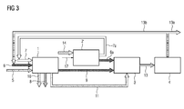
- FIG. 3 shows a third method and a third device for the utilization of emissions of an industrial plant.
- an electrolysis device 2 'in the form of a low-temperature electrolysis unit in detail a PEM electrolysis unit, is used to generate hydrogen 6a and oxygen 7a.
- This is operated at an operating temperature in the range from 0 to 130 ° C., in particular from 50 to 90 ° C., and in a pressure range from 4 to 100 bar, in particular from 10 to 50 bar, with water (in the liquid state).
- the oxygen 7a generated by the electrolysis device 2 ' is optionally used as the oxidizing agent 7 for the combustion of the fuel 6.
- the electrolytically generated hydrogen 6a and the carbon dioxide 9 are supplied separately to a chemical reactor 3 where conversion into a synthetic base or fuel 13 takes place.
- the electrolysis device 2 'downstream chemical reactor 3 has a suitable catalyst and is operated at the same pressure level as the electrolysis device 2'.
- At least part of the waste heat 11 of the emitter 1 is fed, independently of the first emission containing the carbon dioxide 9, directly to the chemical reactor 3 for its heating.
- the generated base or fuel 13 is collected in a collector 4 and used outside the process, 13a, or - at least partially - fed to the emitter 1 as synthetic fuel 13b.
- FIG. 4 shows a fourth method and a fourth device for the utilization of emissions of an industrial plant. Same reference numerals as in FIG. 3 denote the same elements.
- water in the vapor state 10 supplied from the emitter 1 of a condensing unit 15 and the recovered water in the liquid state 14 of the electrolysis device 2 ' is supplied. This water is clean and ready for immediate use, so that cleaning by means of ion exchange units can be omitted.
- At least part of the waste heat 11 of the emitter 1 and the waste heat 11a extracted via the condensing unit 15 from the water in the vapor state 10 are fed directly to the chemical reactor 3 for heating thereof independently of the first emission comprising the carbon dioxide 9.
- FIG. 5 describes a fifth method and a fifth device for the utilization of emissions of an industrial plant. Same reference numerals as in FIG. 3 denote the same elements.
- a second chemical reactor 3 ' is provided, which is additionally connected downstream of the emitter 1 and the electrolysis device 2'.
- the first chemical reactor 3 is supplied with a first emission comprising carbon dioxide 9 from the exhaust gas of the emitter 1, which is reacted with hydrogen 6a from the electrolysis device 2 'to form a first base or fuel 13, for example methane or methanol.
- the second chemical reactor 3 ' is supplied with a further first emission comprising nitrogen 9' from the exhaust gas of the emitter 1, which is reacted with hydrogen 6a from the electrolysis device 2 'to a second base or fuel 13' in the form of ammonia.
- the generated first base or fuel 13 is collected in a first collector 4 and used outside the process, 13a, or - at least partially - fed to the emitter 1 as fuel 13b.
- the generated second base or fuel 13 ' is collected in a second collector 4' and used outside the process.
- the illustrated methods and apparatus may be modified at any time by one skilled in the art without departing from the spirit of the invention.
- the exhaust gas of one or more emitters may be supplied in parallel to a plurality of electrolysis devices and / or chemical reactors, the exhaust gas of several emitters are supplied to only one electrolysis device and / or one chemical reactor, the number of electrolysis devices and chemical reactors may be selected differently.
- the concretely required embodiment of a device depends essentially on the emission quantities to be processed, the power of the electrolysis device used and the power of the respective chemical reactor. Furthermore, it is also possible to use other types of electrolysis devices than those mentioned or simultaneously different types of electrolysis devices.
- the chemical reactors used may differ in structure and catalyst used as they are to be selected according to the emission and desired base or fuel to be treated.
Landscapes
- Chemical & Material Sciences (AREA)
- Organic Chemistry (AREA)
- Chemical Kinetics & Catalysis (AREA)
- Oil, Petroleum & Natural Gas (AREA)
- Engineering & Computer Science (AREA)
- General Chemical & Material Sciences (AREA)
- Analytical Chemistry (AREA)
- Inorganic Chemistry (AREA)
- Electrolytic Production Of Non-Metals, Compounds, Apparatuses Therefor (AREA)
- Treating Waste Gases (AREA)
Priority Applications (2)
| Application Number | Priority Date | Filing Date | Title |
|---|---|---|---|
| EP10153730A EP2360231A1 (fr) | 2010-02-16 | 2010-02-16 | Procédé et dispositif d'évaluation d'émissions d'une installation industrielle |
| PCT/EP2011/051136 WO2011101217A2 (fr) | 2010-02-16 | 2011-01-27 | Procédé et dispositif pour valoriser des émissions d'une installation industrielle |
Applications Claiming Priority (1)
| Application Number | Priority Date | Filing Date | Title |
|---|---|---|---|
| EP10153730A EP2360231A1 (fr) | 2010-02-16 | 2010-02-16 | Procédé et dispositif d'évaluation d'émissions d'une installation industrielle |
Publications (1)
| Publication Number | Publication Date |
|---|---|
| EP2360231A1 true EP2360231A1 (fr) | 2011-08-24 |
Family
ID=42270031
Family Applications (1)
| Application Number | Title | Priority Date | Filing Date |
|---|---|---|---|
| EP10153730A Withdrawn EP2360231A1 (fr) | 2010-02-16 | 2010-02-16 | Procédé et dispositif d'évaluation d'émissions d'une installation industrielle |
Country Status (2)
| Country | Link |
|---|---|
| EP (1) | EP2360231A1 (fr) |
| WO (1) | WO2011101217A2 (fr) |
Cited By (3)
| Publication number | Priority date | Publication date | Assignee | Title |
|---|---|---|---|---|
| CN113046103A (zh) * | 2021-03-17 | 2021-06-29 | 湖南耕农富硒农业科技股份有限公司 | 一种生物质燃料的加工设备及加工方法 |
| DE102023121079A1 (de) * | 2023-08-08 | 2025-02-13 | Khd Humboldt Wedag Gmbh | Verfahren zur Herstellung von Zementklinker mit Verarbeitung von anfallendem Kohlendioxid zu Methanol |
| DE102023126929A1 (de) * | 2023-10-04 | 2025-04-10 | Khd Humboldt Wedag Gmbh | Anlage zur Herstellung von Zement mit Auskopplung von Wärmeenergie |
Families Citing this family (1)
| Publication number | Priority date | Publication date | Assignee | Title |
|---|---|---|---|---|
| EP3196177A1 (fr) | 2016-01-21 | 2017-07-26 | HeidelbergCement AG | Hydrogene comme combustible dans la fabrication de ciment |
Citations (11)
| Publication number | Priority date | Publication date | Assignee | Title |
|---|---|---|---|---|
| JPS57167935A (en) * | 1982-03-12 | 1982-10-16 | Hitachi Zosen Corp | Production of methanol |
| EP0539244A1 (fr) * | 1991-09-10 | 1993-04-28 | Mitsubishi Jukogyo Kabushiki Kaisha | Procédé d'alimentation en énergie en utilisant comme posteur le méthanol |
| US5342702A (en) * | 1993-01-05 | 1994-08-30 | Integrated Energy Development Corp. | Synergistic process for the production of carbon dioxide using a cogeneration reactor |
| US5964908A (en) * | 1996-01-04 | 1999-10-12 | Malina; Mylan | Closed loop energy conversion process |
| WO2000025380A2 (fr) * | 1998-10-27 | 2000-05-04 | Quadrise Limited | Stockage d'energie electrique |
| FR2824493A1 (fr) | 2001-05-09 | 2002-11-15 | Yvan Alfred Schwob | Recyclage du gaz carbonique par retroconversion oxydoreductrice |
| WO2007108014A1 (fr) | 2006-03-20 | 2007-09-27 | Cri Ehf | Procédé de production de carburant liquide à partir de dioxyde de carbone et d'eau |
| DE102006034712A1 (de) * | 2006-07-27 | 2008-01-31 | Steag Saar Energie Ag | Verfahren zur Reduzierung der CO2-Emission fossil befeuerter Kraftwerksanlagen |
| DE102006035893A1 (de) * | 2006-07-31 | 2008-02-07 | Wolf, Bodo M., Dr. | Verfahren zur Wiederaufarbeitung von Verbrennungsprodukten fossiler Brennstoffe |
| WO2008054230A1 (fr) * | 2006-11-02 | 2008-05-08 | Rco2 As | Procédé de production de dioxyde de carbone et de méthane par réaction gazeuse catalytique |
| DE102009007567A1 (de) | 2008-03-10 | 2009-09-17 | Harzfeld, Edgar, Prof. Dr.-Ing. | Verfahren zur Herstellung von Methanol durch Verwertung von Kohlendioxid aus Abgasen fossil betriebener Energieerzeugungsanlagen |
-
2010
- 2010-02-16 EP EP10153730A patent/EP2360231A1/fr not_active Withdrawn
-
2011
- 2011-01-27 WO PCT/EP2011/051136 patent/WO2011101217A2/fr not_active Ceased
Patent Citations (11)
| Publication number | Priority date | Publication date | Assignee | Title |
|---|---|---|---|---|
| JPS57167935A (en) * | 1982-03-12 | 1982-10-16 | Hitachi Zosen Corp | Production of methanol |
| EP0539244A1 (fr) * | 1991-09-10 | 1993-04-28 | Mitsubishi Jukogyo Kabushiki Kaisha | Procédé d'alimentation en énergie en utilisant comme posteur le méthanol |
| US5342702A (en) * | 1993-01-05 | 1994-08-30 | Integrated Energy Development Corp. | Synergistic process for the production of carbon dioxide using a cogeneration reactor |
| US5964908A (en) * | 1996-01-04 | 1999-10-12 | Malina; Mylan | Closed loop energy conversion process |
| WO2000025380A2 (fr) * | 1998-10-27 | 2000-05-04 | Quadrise Limited | Stockage d'energie electrique |
| FR2824493A1 (fr) | 2001-05-09 | 2002-11-15 | Yvan Alfred Schwob | Recyclage du gaz carbonique par retroconversion oxydoreductrice |
| WO2007108014A1 (fr) | 2006-03-20 | 2007-09-27 | Cri Ehf | Procédé de production de carburant liquide à partir de dioxyde de carbone et d'eau |
| DE102006034712A1 (de) * | 2006-07-27 | 2008-01-31 | Steag Saar Energie Ag | Verfahren zur Reduzierung der CO2-Emission fossil befeuerter Kraftwerksanlagen |
| DE102006035893A1 (de) * | 2006-07-31 | 2008-02-07 | Wolf, Bodo M., Dr. | Verfahren zur Wiederaufarbeitung von Verbrennungsprodukten fossiler Brennstoffe |
| WO2008054230A1 (fr) * | 2006-11-02 | 2008-05-08 | Rco2 As | Procédé de production de dioxyde de carbone et de méthane par réaction gazeuse catalytique |
| DE102009007567A1 (de) | 2008-03-10 | 2009-09-17 | Harzfeld, Edgar, Prof. Dr.-Ing. | Verfahren zur Herstellung von Methanol durch Verwertung von Kohlendioxid aus Abgasen fossil betriebener Energieerzeugungsanlagen |
Cited By (4)
| Publication number | Priority date | Publication date | Assignee | Title |
|---|---|---|---|---|
| CN113046103A (zh) * | 2021-03-17 | 2021-06-29 | 湖南耕农富硒农业科技股份有限公司 | 一种生物质燃料的加工设备及加工方法 |
| CN113046103B (zh) * | 2021-03-17 | 2021-09-14 | 湖南耕农富硒农业科技股份有限公司 | 一种生物质燃料的加工设备及加工方法 |
| DE102023121079A1 (de) * | 2023-08-08 | 2025-02-13 | Khd Humboldt Wedag Gmbh | Verfahren zur Herstellung von Zementklinker mit Verarbeitung von anfallendem Kohlendioxid zu Methanol |
| DE102023126929A1 (de) * | 2023-10-04 | 2025-04-10 | Khd Humboldt Wedag Gmbh | Anlage zur Herstellung von Zement mit Auskopplung von Wärmeenergie |
Also Published As
| Publication number | Publication date |
|---|---|
| WO2011101217A2 (fr) | 2011-08-25 |
| WO2011101217A3 (fr) | 2012-07-19 |
Similar Documents
| Publication | Publication Date | Title |
|---|---|---|
| EP2360230A1 (fr) | Procédé et dispositif d'évaluation d'émissions d'une centrale | |
| DE102016219990B4 (de) | Verfahren zur Abscheidung und Lagerung von Kohlendioxid und/oder Kohlenmonoxid aus einem Abgas | |
| EP3019581B1 (fr) | Procédé de méthanisation et centrale comprenant la méthanisation de co2 provenant des gaz brûlés de la centrale | |
| EP2818227B1 (fr) | Procédé d'opération d'un four droit produisant de la chaux vive, de la dolomite, de la magnésie ou du ciment et installation de four droit destinée à la production de chaux vive, de dolomite, de magnésie ou de ciment | |
| DE69229839T2 (de) | Methode zur Herstellung von Methanol unter Verwendung der Wärme eines Kernkraftwerkes | |
| EP3008218B1 (fr) | Haut fourneau et procédé servant à faire fonctionner un haut fourneau | |
| DE102018202594B4 (de) | Verfahren zur Herstellung von Eisenschwamm insbesondere in einem Direktreduktionsprozess | |
| DE102014203039A1 (de) | Verfahren und Vorrichtung zur Trennung von Abgas bei der Verbrennung bestimmter Metalle | |
| EP3156519B1 (fr) | Procédé et appareil de production d'un hydrocarbure | |
| EP2129745A2 (fr) | Processus de centrale électrique en cascade d'un genre nouveau et procédé pour produire des transporteurs d'hydrogène utilisables de manière réversible dans un tel processus de centrale électrique | |
| WO2016128102A1 (fr) | Procédé permettant de faire fonctionner une centrale électrique alimentée par des combustibles fossiles et centrale électrique destinée à brûler des combustibles fossiles | |
| WO2012095329A2 (fr) | Procédé de traitement d'un gaz de combustion contenant du dioxyde de carbone provenant d'un processus d'électrofusion | |
| DE102013010855A1 (de) | Verfahren zum Betreiben von Verbrennungsprozesse ausführenden und Kohlenstoffdioxid emittierenden Industrieanlagen sowie Industrieanlage insbesondere zur Durchführung des Verfahrens | |
| DE102014103311A1 (de) | Methanisierungsverfahren und Kraftwerk umfassend die CO2-Methanisierung aus Kraftwerksrauchgas | |
| DE102020118546A1 (de) | Verfahren zum Betrieb einer Anlage zur Herstellung von Zementklinker | |
| EP2360231A1 (fr) | Procédé et dispositif d'évaluation d'émissions d'une installation industrielle | |
| EP3526315B1 (fr) | Procédé pour la production de méthane | |
| WO2023208410A1 (fr) | Méthode et système de production d'un produit de traitement | |
| WO2012013485A1 (fr) | Procédé de réutilisation d'effluents gazeux contenant du co2 | |
| DE102018213482A1 (de) | Bereitstellung von Kohlenstoffdioxid mittels sauerstoffbasierter Verbrennung | |
| DE102014209527A1 (de) | Verfahren zum Verbrennen einer Legierung eines elektropositiven Metalls | |
| EP3541964A1 (fr) | Procédé et dispositif de fonctionnement d'un réacteur de réduction directe pour la production de fer à réduction directe à partir de minerai de fer | |
| DE102016208938A1 (de) | Verfahren und Anlage zur Erzeugung eines Kohlenwasserstoffs | |
| DE102014209529A1 (de) | Verbrennung von Lithium bei unterschiedlichen Temperaturen, Drücken und Gasüberschüssen mit porösen Rohren als Brenner | |
| DE102015223938A1 (de) | Verfahren und Vorrichtung zum Speichern elektrischer Energie mittels einer chemischen Synthese |
Legal Events
| Date | Code | Title | Description |
|---|---|---|---|
| PUAI | Public reference made under article 153(3) epc to a published international application that has entered the european phase |
Free format text: ORIGINAL CODE: 0009012 |
|
| PUAI | Public reference made under article 153(3) epc to a published international application that has entered the european phase |
Free format text: ORIGINAL CODE: 0009012 |
|
| AK | Designated contracting states |
Kind code of ref document: A1 Designated state(s): AT BE BG CH CY CZ DE DK EE ES FI FR GB GR HR HU IE IS IT LI LT LU LV MC MK MT NL NO PL PT RO SE SI SK SM TR |
|
| AX | Request for extension of the european patent |
Extension state: AL BA RS |
|
| STAA | Information on the status of an ep patent application or granted ep patent |
Free format text: STATUS: THE APPLICATION HAS BEEN WITHDRAWN |
|
| 18W | Application withdrawn |
Effective date: 20111206 |