EP2360334A2 - Cylindre de fermeture - Google Patents
Cylindre de fermeture Download PDFInfo
- Publication number
- EP2360334A2 EP2360334A2 EP11152750A EP11152750A EP2360334A2 EP 2360334 A2 EP2360334 A2 EP 2360334A2 EP 11152750 A EP11152750 A EP 11152750A EP 11152750 A EP11152750 A EP 11152750A EP 2360334 A2 EP2360334 A2 EP 2360334A2
- Authority
- EP
- European Patent Office
- Prior art keywords
- key
- recess
- cylinder core
- locking
- lock cylinder
- Prior art date
- Legal status (The legal status is an assumption and is not a legal conclusion. Google has not performed a legal analysis and makes no representation as to the accuracy of the status listed.)
- Granted
Links
- 230000000903 blocking effect Effects 0.000 claims description 43
- 238000003780 insertion Methods 0.000 claims description 23
- 230000037431 insertion Effects 0.000 claims description 23
- 238000013475 authorization Methods 0.000 claims description 12
- 238000001514 detection method Methods 0.000 claims description 3
- 238000013461 design Methods 0.000 description 8
- 230000015572 biosynthetic process Effects 0.000 description 3
- 238000011161 development Methods 0.000 description 2
- 230000018109 developmental process Effects 0.000 description 2
- 230000007704 transition Effects 0.000 description 2
- 230000000295 complement effect Effects 0.000 description 1
- 230000001419 dependent effect Effects 0.000 description 1
- 238000005553 drilling Methods 0.000 description 1
- 238000004519 manufacturing process Methods 0.000 description 1
- 238000000034 method Methods 0.000 description 1
- 238000003801 milling Methods 0.000 description 1
- 238000012546 transfer Methods 0.000 description 1
Images

Classifications
-
- E—FIXED CONSTRUCTIONS
- E05—LOCKS; KEYS; WINDOW OR DOOR FITTINGS; SAFES
- E05B—LOCKS; ACCESSORIES THEREFOR; HANDCUFFS
- E05B27/00—Cylinder locks or other locks with tumbler pins or balls that are set by pushing the key in
- E05B27/0042—Cylinder locks or other locks with tumbler pins or balls that are set by pushing the key in with additional key identifying function, e.g. with use of additional key operated rotor-blocking elements, not of split pin tumbler type
-
- E—FIXED CONSTRUCTIONS
- E05—LOCKS; KEYS; WINDOW OR DOOR FITTINGS; SAFES
- E05B—LOCKS; ACCESSORIES THEREFOR; HANDCUFFS
- E05B15/00—Other details of locks; Parts for engagement by bolts of fastening devices
- E05B15/08—Key guides; Key pins ; Keyholes; Keyhole finders
-
- E—FIXED CONSTRUCTIONS
- E05—LOCKS; KEYS; WINDOW OR DOOR FITTINGS; SAFES
- E05B—LOCKS; ACCESSORIES THEREFOR; HANDCUFFS
- E05B47/00—Operating or controlling locks or other fastening devices by electric or magnetic means
- E05B47/0001—Operating or controlling locks or other fastening devices by electric or magnetic means with electric actuators; Constructional features thereof
-
- E—FIXED CONSTRUCTIONS
- E05—LOCKS; KEYS; WINDOW OR DOOR FITTINGS; SAFES
- E05B—LOCKS; ACCESSORIES THEREFOR; HANDCUFFS
- E05B19/00—Keys; Accessories therefor
- E05B19/0017—Key profiles
Definitions
- the present invention relates to a lock cylinder with a cylinder body in which a cylinder core is rotatably received, which cylinder core has a lock cylinder for receiving a key, which key has a stop, over which the insertion depth of the key is limited in the cylinder core, wherein at least one locking element in Cylinder core can be arranged, which extends at least partially into the closing channel.
- the stop for limiting the insertion depth of the key is located on the outside of the cylinder core.
- the attack is often formed on the key crayon and is located at the transition point between the key crayon and the key shaft on which the key bit is pronounced. If the key is inserted into the cylinder core, then the stop reaches the key when reaching the required insertion depth to rest against the end face of the cylinder core. In this position, the key bit corresponds with locking elements, which are accommodated in the cylinder body. It is crucial that the key is inserted in an exact insertion depth into the closing channel. Only then can it be ensured that the locking elements are brought into the correct position to close the lock cylinder.
- the stop on the key is used to align the position of the key bit in the direction of the key shank. Furthermore, it is possible to mill the stop in one step with the key bit, so that the exact position of the stop can correspond to the position of the key bit.
- the coding of the key initially takes place via a profile characteristic of the key shank, which corresponds to the profile characteristic of the closing channel in the cylinder core. Only keys that have a profile expression that corresponds to the profile expression of the closing channel, can also be introduced into this. It is known to slightly vary the profile characteristics of the key in order to provide different key authorizations for a group of keys with a first profile characteristic, which is distinguished from another group of keys of another profile specification. Thus, different locking hierarchies can be created so that, for example, keys of a high locking hierarchy can be inserted into all lock cylinders which belong to a locking system. However, a demarkrenzende group of keys can not be plugged into all lock cylinders, if the profile expression of the key shaft prevents this.
- locking authorizations can be subdivided into different lock hierarchies, in particular by the foundation of lock system cylinders, which belong to a locking system, being assembled accordingly.
- the codability of the keys is possible, which is possible within different locking authorizations of a locking system.
- a lock cylinder which has a cylinder body in which a cylinder core is rotatably received, which cylinder core has a closing channel for receiving a key, which key has a stop, via which the insertion depth of the key is limited in the cylinder core, wherein at least one blocking element can be arranged in the cylinder core, which extends at least partially into the closing channel, wherein the key a recess formed corresponding to the locking member so that the locking member extends into the recess when the key is inserted into the locking channel to create different locking authorizations.
- the lock cylinder Due to the inventive design of the lock cylinder with a blocking element in the cylinder core, which extends at least partially into the closing channel, and with a recess which is formed corresponding to the blocking element, the advantage is achieved that a further subdivision into different closing hierarchies is made possible.
- the security of the lock cylinder is increased by the arrangement of the locking element excludes key to the closure of the lock cylinder, which do not have a corresponding recess with the blocking element.
- the further advantage can be achieved that the possibility of additional coding is given by a specific arrangement of the locking element in the cylinder core and a corresponding recess in the key, in addition to the specific design of the key bit on the key shank and in particular the specific embodiment of the key shank with corresponding profile characteristics offers a further possibility of variation of key groups within a locking system.
- the cylinder core can be designed to receive keys of different key profiles.
- the geometric design of the key bit as well as the profile of the key shaft, ie in the key blank, are designated by a key profile.
- the formation of the cylinder core for receiving keys of different key profiles thus designates the geometric design of the closing channel.
- the possible codes of the lock cylinder, based on the geometric design of the closing channel on the one hand and based on the Coding of the key bit on the other hand can overlap each other. This creates a possible combinatorics by multiplying the variation on the one hand of the closing channel and on the other hand, the foundation of the lock cylinder by the Zuhaltiata.
- the inventive design of a lock cylinder creates a further overlay by the geometric design and the arrangement of the locking element in the cylinder core corresponding to the recess in the key.
- the arrangement of the blocking element in the cylinder core can be determined such that keys can be subdivided into different locking authorizations.
- the geometric determination of the recess on the key can be determined in such a way that keys can also be subdivided into different locking authorizations. For example, if the recess on the key for unauthorized use in a lock cylinder designed too short, and pushes the locking element upon insertion of the key in the lock channel to the end of the recess, the key can not be sufficiently far into the lock channel. As a result, the lock can not be locked with the corresponding key.
- a plurality of locking elements can be arranged in the cylinder core. If a plurality of locking elements arranged in the cylinder core, the key, which is designed to correspond with the lock cylinder, also have a corresponding number of recesses. Furthermore, locking elements may be arranged in the cylinder core such that two or more locking elements can engage in only one recess.
- the blocking elements may be formed geometrically different, for example, locking elements of different lengths may be provided, which protrude differently far into the closing channel.
- recesses of different depths can be formed in the key, so that a blocking element which projects far into the closing channel corresponds to a recess which is deep is trained.
- a blocking element which protrudes with a smaller length into the closing channel, can correspond to a recess which has a smaller depth.
- a plurality of locking elements corresponding to a plurality of recesses further increase the combinatorics between lock cylinders and keys.
- two recesses can be introduced on both flat sides opposite one another in the key shank. Between the recesses thus forms a web area of reduced width. If the cutouts are made in the spine of the key, a key back of variable width is created in order to correspond to blocking elements introduced opposite in the cylinder core.
- the locking element extends along the recess of the key when the key is inserted, wherein the recess in the direction of the closing channel is longer than the length over which the blocking element runs in the recess. At least the recess may have at least the length which is necessary to insert the key sufficiently deep into the closing channel. Although the length of the recess may be dimensioned such that the locking element abuts the end of the recess, whereby the path is limited, via which the key is inserted into the lock channel. However, there is the disadvantage that the length of the recess must correspond exactly with the positioning of the key bit on the key shaft.
- the lock cylinder according to the invention relates to an embodiment in which a stop on the key is provided, which is designed to bear against the end face of the cylinder core. If the recess were to be dimensioned in length such that the blocking element should additionally limit the insertion depth of a corresponding key, there would be a double fit, which would have to be produced technically with no reasonable outlay. Consequently, the embodiment of the invention provides that the recess in the key has a greater length than the length along which the blocking element runs in the recess until the stop on the key comes against the end face of the cylinder core to the plant.
- the cylinder core can have at least one receptacle into which the blocking element can be introduced.
- a plurality of receptacles may be provided in the cylinder core, in which optional locking elements can be introduced, so that different locking authorizations can be generated.
- the cylinder core may have a plurality of receptacles, in which, however, not necessarily a blocking element must be used. If, for example, a lock cylinder is assembled as part of a locking system individually with locking elements, it can be decided at the same time whether and how many locking elements are used in the seats. Consequently, blocking elements need not be inserted into the receptacle in principle in order to produce the function of the lock cylinder.
- variable arrangement of locking elements in the cylinder core also has the advantage that there is no standard position of locking elements, whereby a manipulation of the lock cylinder is further complicated.
- locking elements can also be post-assembled during the use of a lock cylinder, for example, to transfer a lock cylinder within a lock authorization from a first shooting hierarchy level to a second closing hierarchy level. For example, this can be done by simply repositioning blocking elements.
- the blocking element may be formed as a locking pin and the receptacle in the cylinder core as a bore into which the locking pin can be introduced.
- the locking pin can be pressed into the hole or the locking pin is pressed in the hole.
- the locking pin can also be designed in the form of a stud, which is screwed so deep into the receptacle that a front end of the stud protrudes with a desired portion in the closing channel.
- the locking pin may be stepped in order to correspond with steps which are present in the recess on the key.
- the combinatorics between key and lock cylinder can be further increased.
- the locking pin can thus be formed as a cylindrical pin, as a stepped cylinder pin, as a screw or other element with an at least elongated extent.
- the blocking element may be formed as a locking ring and the receptacle in the cylinder core as a groove into which the locking ring can be introduced.
- the locking ring may be formed, for example in the form of a retaining ring, in particular a snap ring.
- the introduced in the cylinder core groove for receiving the locking ring cuts on a portion of the closing channel, so that a portion of the locking ring protrudes into the closing channel.
- the recess on the key which corresponds to the locking ring, may preferably be introduced in the back of the key shaft, which is formed opposite to the key bit on the key shaft.
- the groove corresponds to a reduction of the key back, so that the full cross section of the key back, for example, is formed only on a certain portion of the key shank.
- the blocking element may be formed as an insert element and the receptacle in the cylinder core as an insertion pocket.
- the insert element may for example be designed crescent-shaped, wherein the curved side of the crescent corresponds to the lateral surface of the cylinder core. The straight side of the crescent-shaped insert element protrudes into the closing channel to correspond with the recess in the key.
- the insert element at least in the region in which it passes through the closing channel, have a profiling which corresponds to a profile formation of the key shank. If, for example, the insert element has a one-sided notch, then this notch can correspond to a recess present laterally in the flat side of the key.
- the key may in particular be designed as a flat key and have a key back opposite the spine, wherein at least one recess is preferably introduced in the spine.
- This recess can correspond, for example, with the locking element designed as a locking element or as a blocking element.
- a recess in the flat side of the key can be introduced, which in particular corresponds to a blocking element which is designed as a locking pin and inserted in a bore in the cylinder core.
- an electrical means can be provided with which preferably the use of a suitable key can be detected.
- an electrically controllable actuator can be provided which can be activated upon detection of a suitable key by the electrical means, in particular in order to release a closure of the lock cylinder. If a suitable key is detected via the electrical means, the electrical means can transmit the detection to the electrically controllable actuator. This can for example be designed so that only when the actuator is activated, the closure of the lock cylinder is released.
- the electrical means is preferably such in the cylinder core or in Cylinder body arranged that the electrical means detects the matching key only when it has been fully inserted into the closing channel.
- the electrical means can not detect the key and the lock release actuator is not activated. Consequently, the electrically controllable actuator can activate only when a key is executed and used with a matching with respect to the existing blocking element in the cylinder core recess.
- FIG. 1 shows an embodiment of a cylinder core 10, in which a key 12 is inserted.
- the key 12 can be inserted into a closing channel (not visible in the perspective) until a stop 13 on the key 12 abuts against the front end face 18 of the cylinder core 10.
- the key 12 is designed as a flat key 12 and has a key profile 16.
- the key profile 16 describes in the present case both the geometric shape of the sawtooth profile of the key bit and the profile expression of the key shank cross section.
- the stop 13 is located on the key 17 in the transition into the key shank on which the key profile 16 is formed.
- the cylinder core 10 has a receptacle 19 in the form of a bore 19 into which a blocking element 14, designed as a locking pin 14a, can be inserted.
- a part of the blocking element 14 projects into the closing channel. If the key 12 is inserted into the closing channel, the key shaft also passes through the area in which the blocking element 14a projects into the closing channel.
- On the key shank a recess 15 is provided, which is introduced in the flat side 23 of the flat key 12, for example, as a milled cutout.
- the key 12 can be inserted so deep into the lock channel until the stop 13 comes to the key 17 against the end face 18 of the cylinder core 10 to the plant. Consequently, the key 12 can be used with the cylinder core 10 of the arrangement shown to close the lock cylinder.
- FIG. 2 shows in a detailed view of the arrangement of the blocking element 14 in the cylinder core 10, which is designed as a locking pin 14a.
- the locking pin 14 a is shown in the section which extends into the closing channel 11 in the cylinder core 10 hineinerstreckt.
- the key 12 is also shown in sections and has the recess 15, so that upon insertion of the key 12 of the locking pin 14 a in the recess 15 along. The insertion of the key 12 takes place in the image plane from left to right in the closing channel 11.
- the view also illustrates that the locking pin 14a does not come to the end of the recess 15 to the plant. Consequently, the blocking element 14 does not serve to limit the insertion depth of the key 12 into the cylinder core 10.
- FIGS. 3 and 4 show a further embodiment of a cylinder core 10 and a key 12.
- the cylinder core 10 has a receptacle 20 which is formed as a circumferential groove 20 in the cylinder core 10.
- the blocking element 14 is designed as a locking ring 14b. If the locking ring 14b inserted into the groove 20 in the cylinder core 10, so passes through a portion of the locking ring 10b the closing channel 11. This section corresponds to the recess 15 which is inserted in the key back 22 of the key shank. By arranging the recess 15 in the spine 22, the key 12 can be inserted sufficiently deep into the closing channel 11 to use the key 12 to close the lock cylinder.
- the blocking element 14 may be formed, for example, as a snap ring, or the blocking element 14 is otherwise resiliently resilient in such a way that it can be arranged in the groove 20 in a self-holding manner.
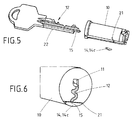
- FIG. 5 shows a still further embodiment of a cylinder core 10 and a key 12 according to the present invention.
- the cylinder core 10 has a receptacle 21, which is designed as an insertion pocket 21.
- a blocking element 14 can be inserted, which is designed as an insert element 14c.
- the insert member 14c has a crescent-shaped cross section, and the curved side of the crescent-shaped cross-section closes after insertion into the insertion pocket 21 with the lateral surface of the cylinder core 10 from.
- the key 12 in turn has a recess 15 which in such Key back 22 is arranged, that the key 12 is sufficiently deep inserted into the closing channel of the cylinder core 10.
- FIG. 6 shows a cross-sectional view of the cylinder core 10 according to Fig. 5 with a closing channel 11 into which a flat key 12 is inserted.
- the cross-sectional plane corresponds to the plane for arranging an insert element 14c according to the exemplary embodiment in FIG FIG. 5 , In the insertion pocket 21, the insert member 14 c is inserted and the cross-cut key 12 shown is completely inserted into the closing channel 11. This is achieved by the recess 15, which according to the view in FIG. 5 in the key back 22 is introduced.
- the invention is not limited in its execution to the above-mentioned preferred embodiment. Rather, a number of variants is conceivable, which makes use of the solution shown in other types of embodiments. All of the claims, the description or the drawings resulting features and / or advantages, including design details, spatial arrangements and method steps may be essential to the invention both in itself and in a variety of combinations.
- the configuration of the blocking element 14 as a locking pin 14a, as a locking ring 14b, or insert element 14c be combined with each other, so that in a single cylinder core 10 a plurality of receptacles 19, 20, 21 are introduced, either as a bore 19, as a groove 20 or are formed as an insertion pocket 21.
- the combinatorics of a locking system can be further increased.
- the recess 15 for example, once on the key back 22 and once in the flat side 23 of the flat key 12 is introduced, the two recesses 15 do not affect each other.
- a plurality of locking elements 14 correspond with a recess 15 in the key 12.
Landscapes
- Lock And Its Accessories (AREA)
Applications Claiming Priority (1)
| Application Number | Priority Date | Filing Date | Title |
|---|---|---|---|
| DE201010001909 DE102010001909A1 (de) | 2010-02-12 | 2010-02-12 | Schließzylinder |
Publications (3)
| Publication Number | Publication Date |
|---|---|
| EP2360334A2 true EP2360334A2 (fr) | 2011-08-24 |
| EP2360334A3 EP2360334A3 (fr) | 2013-01-23 |
| EP2360334B1 EP2360334B1 (fr) | 2015-04-01 |
Family
ID=44168123
Family Applications (1)
| Application Number | Title | Priority Date | Filing Date |
|---|---|---|---|
| EP20110152750 Not-in-force EP2360334B1 (fr) | 2010-02-12 | 2011-01-31 | Cylindre de fermeture |
Country Status (2)
| Country | Link |
|---|---|
| EP (1) | EP2360334B1 (fr) |
| DE (1) | DE102010001909A1 (fr) |
Cited By (4)
| Publication number | Priority date | Publication date | Assignee | Title |
|---|---|---|---|---|
| WO2015000963A1 (fr) * | 2013-07-03 | 2015-01-08 | Ernst Keller | Clé et cylindre rotatif |
| EP3366870A1 (fr) * | 2017-02-24 | 2018-08-29 | Assa Ab | Système de serrure cylindrique et de clé |
| ES2753597A1 (es) * | 2018-09-13 | 2020-04-13 | Talleres De Escoriaza S A U | Sistema de cerradura con llave y cilindro de cerradura |
| EP3933152A1 (fr) * | 2020-06-30 | 2022-01-05 | ABUS August Bremicker Söhne KG | Cylindre de fermeture, dispositif de fermeture, système de fermeture, clé et ébauche de clé |
Families Citing this family (1)
| Publication number | Priority date | Publication date | Assignee | Title |
|---|---|---|---|---|
| EP3366871A1 (fr) | 2017-02-24 | 2018-08-29 | Assa Ab | Système de serrure et clé à barillet |
Family Cites Families (11)
| Publication number | Priority date | Publication date | Assignee | Title |
|---|---|---|---|---|
| AT371880B (de) * | 1980-09-25 | 1983-08-10 | Evva Werke | Flachschluessel |
| DE3216481A1 (de) * | 1982-04-30 | 1983-11-03 | Fa. Aug. Winkhaus, 4404 Telgte | Schluesselbetaetigter schliesszylinder |
| DE3722870A1 (de) * | 1987-07-10 | 1989-01-26 | Dom Sicherheitstechnik | Vorrichtung zur diebstahlsicherung von kraftfahrzeugraedern |
| DE8900042U1 (de) * | 1989-01-04 | 1989-03-02 | BKS GmbH, 5620 Velbert | Zylinderschlüssel |
| DE19711992A1 (de) * | 1997-03-14 | 1998-09-17 | Ikon Praezisionstechnik | Schließzylinder |
| DE59900185D1 (de) * | 1998-04-04 | 2001-09-13 | Schlossicherungen Gera Gmbh | Schliesszylinder mit zugeordnetem Flachschlüssel im variablen Stufenprofil |
| DE19919568A1 (de) * | 1999-04-29 | 2000-11-02 | Bremicker Soehne Kg A | Schließsystem |
| BE1016106A3 (fr) * | 2004-06-30 | 2006-03-07 | Euro Locks Sa | Rotor et clefs pour serrure, serrure munie d'un tel rotor et de telles clefs, et utilisation de ceux-ci. |
| DE102004063126B3 (de) * | 2004-12-22 | 2006-06-01 | Hewi Heinrich Wilke Gmbh | Elektromechanisches Schließsystem |
| DE102005030408B3 (de) * | 2005-06-30 | 2007-02-08 | Niederdrenk, Gerd, Dipl.-Ing. | Zylinderschloss |
| AT9156U1 (de) * | 2006-01-05 | 2007-05-15 | Evva Werke | Zylinderschloss mit schieber sowie flachschlüssel mit steuerrippe |
-
2010
- 2010-02-12 DE DE201010001909 patent/DE102010001909A1/de not_active Withdrawn
-
2011
- 2011-01-31 EP EP20110152750 patent/EP2360334B1/fr not_active Not-in-force
Non-Patent Citations (1)
| Title |
|---|
| None |
Cited By (4)
| Publication number | Priority date | Publication date | Assignee | Title |
|---|---|---|---|---|
| WO2015000963A1 (fr) * | 2013-07-03 | 2015-01-08 | Ernst Keller | Clé et cylindre rotatif |
| EP3366870A1 (fr) * | 2017-02-24 | 2018-08-29 | Assa Ab | Système de serrure cylindrique et de clé |
| ES2753597A1 (es) * | 2018-09-13 | 2020-04-13 | Talleres De Escoriaza S A U | Sistema de cerradura con llave y cilindro de cerradura |
| EP3933152A1 (fr) * | 2020-06-30 | 2022-01-05 | ABUS August Bremicker Söhne KG | Cylindre de fermeture, dispositif de fermeture, système de fermeture, clé et ébauche de clé |
Also Published As
| Publication number | Publication date |
|---|---|
| DE102010001909A1 (de) | 2011-08-18 |
| EP2360334B1 (fr) | 2015-04-01 |
| EP2360334A3 (fr) | 2013-01-23 |
Similar Documents
| Publication | Publication Date | Title |
|---|---|---|
| EP0866906B1 (fr) | Dispositif de verrouillage avec serrure a pompe et clef plate | |
| EP2314807B1 (fr) | Système de verrouillage | |
| DE2717799A1 (de) | Zylinderschloss | |
| EP1252408B1 (fr) | Cylindre de fermeture rotatif pour serrure de securite | |
| EP2310598B1 (fr) | Serrure a pompe comportant un boitier cylindrique et cle plate pour une serrure a pompe | |
| EP3279412B1 (fr) | Clé ou ébauche de clé pour un cylindre coulissant et cylindre coulissant correspondant | |
| EP2360334B1 (fr) | Cylindre de fermeture | |
| DE102014119678A1 (de) | Schließzylinder, Schlüssel und Schlüsselrohling | |
| EP2890856B1 (fr) | Ébauche, clé de sécurité, système de verrouillage et procédé de fabrication | |
| EP3191663B1 (fr) | Clé | |
| EP4047161A1 (fr) | Clés, clés et barillets | |
| DE102010012261B4 (de) | Schließsystem | |
| EP1333136B1 (fr) | Serrure cylindrique | |
| DE102013103790A1 (de) | Kodierung über Sperrbalken | |
| EP2619387A1 (fr) | Cylindre de serrure rotatif et clé de sûreté | |
| EP2078808B1 (fr) | Clé pour une serrure cylindrique | |
| EP1333135B1 (fr) | Serrure cylindrique | |
| AT9156U1 (de) | Zylinderschloss mit schieber sowie flachschlüssel mit steuerrippe | |
| WO2015000963A1 (fr) | Clé et cylindre rotatif | |
| AT503051B1 (de) | Zylinderschloss und flachschlüssel | |
| EP2025839B1 (fr) | Combinaison d'une clé et d'un verrou | |
| AT503121B1 (de) | Zylinderschloss sowie flachschlüssel | |
| EP2681386A2 (fr) | Cylindre de serrure rotatif | |
| EP2075394A1 (fr) | Procédé de fabrication d'une serrure cylindrique | |
| HK1239772B (en) | Key |
Legal Events
| Date | Code | Title | Description |
|---|---|---|---|
| PUAI | Public reference made under article 153(3) epc to a published international application that has entered the european phase |
Free format text: ORIGINAL CODE: 0009012 |
|
| PUAI | Public reference made under article 153(3) epc to a published international application that has entered the european phase |
Free format text: ORIGINAL CODE: 0009012 |
|
| AK | Designated contracting states |
Kind code of ref document: A2 Designated state(s): AL AT BE BG CH CY CZ DE DK EE ES FI FR GB GR HR HU IE IS IT LI LT LU LV MC MK MT NL NO PL PT RO RS SE SI SK SM TR |
|
| AX | Request for extension of the european patent |
Extension state: BA ME |
|
| PUAL | Search report despatched |
Free format text: ORIGINAL CODE: 0009013 |
|
| AK | Designated contracting states |
Kind code of ref document: A3 Designated state(s): AL AT BE BG CH CY CZ DE DK EE ES FI FR GB GR HR HU IE IS IT LI LT LU LV MC MK MT NL NO PL PT RO RS SE SI SK SM TR |
|
| AX | Request for extension of the european patent |
Extension state: BA ME |
|
| RIC1 | Information provided on ipc code assigned before grant |
Ipc: E05B 47/00 20060101ALI20121217BHEP Ipc: E05B 27/02 20060101AFI20121217BHEP |
|
| 17P | Request for examination filed |
Effective date: 20130723 |
|
| RBV | Designated contracting states (corrected) |
Designated state(s): AL AT BE BG CH CY CZ DE DK EE ES FI FR GB GR HR HU IE IS IT LI LT LU LV MC MK MT NL NO PL PT RO RS SE SI SK SM TR |
|
| 17Q | First examination report despatched |
Effective date: 20130919 |
|
| GRAP | Despatch of communication of intention to grant a patent |
Free format text: ORIGINAL CODE: EPIDOSNIGR1 |
|
| INTG | Intention to grant announced |
Effective date: 20141212 |
|
| GRAS | Grant fee paid |
Free format text: ORIGINAL CODE: EPIDOSNIGR3 |
|
| GRAA | (expected) grant |
Free format text: ORIGINAL CODE: 0009210 |
|
| AK | Designated contracting states |
Kind code of ref document: B1 Designated state(s): AL AT BE BG CH CY CZ DE DK EE ES FI FR GB GR HR HU IE IS IT LI LT LU LV MC MK MT NL NO PL PT RO RS SE SI SK SM TR |
|
| REG | Reference to a national code |
Ref country code: GB Ref legal event code: FG4D Free format text: NOT ENGLISH |
|
| RAP2 | Party data changed (patent owner data changed or rights of a patent transferred) |
Owner name: DORMA DEUTSCHLAND GMBH |
|
| REG | Reference to a national code |
Ref country code: CH Ref legal event code: EP |
|
| REG | Reference to a national code |
Ref country code: IE Ref legal event code: FG4D Free format text: LANGUAGE OF EP DOCUMENT: GERMAN |
|
| REG | Reference to a national code |
Ref country code: DE Ref legal event code: R096 Ref document number: 502011006420 Country of ref document: DE Effective date: 20150507 |
|
| REG | Reference to a national code |
Ref country code: AT Ref legal event code: REF Ref document number: 719197 Country of ref document: AT Kind code of ref document: T Effective date: 20150515 |
|
| REG | Reference to a national code |
Ref country code: SE Ref legal event code: TRGR |
|
| REG | Reference to a national code |
Ref country code: NL Ref legal event code: VDEP Effective date: 20150401 |
|
| REG | Reference to a national code |
Ref country code: LT Ref legal event code: MG4D |
|
| PG25 | Lapsed in a contracting state [announced via postgrant information from national office to epo] |
Ref country code: NL Free format text: LAPSE BECAUSE OF FAILURE TO SUBMIT A TRANSLATION OF THE DESCRIPTION OR TO PAY THE FEE WITHIN THE PRESCRIBED TIME-LIMIT Effective date: 20150401 |
|
| PG25 | Lapsed in a contracting state [announced via postgrant information from national office to epo] |
Ref country code: LT Free format text: LAPSE BECAUSE OF FAILURE TO SUBMIT A TRANSLATION OF THE DESCRIPTION OR TO PAY THE FEE WITHIN THE PRESCRIBED TIME-LIMIT Effective date: 20150401 Ref country code: CZ Free format text: LAPSE BECAUSE OF FAILURE TO SUBMIT A TRANSLATION OF THE DESCRIPTION OR TO PAY THE FEE WITHIN THE PRESCRIBED TIME-LIMIT Effective date: 20150401 Ref country code: ES Free format text: LAPSE BECAUSE OF FAILURE TO SUBMIT A TRANSLATION OF THE DESCRIPTION OR TO PAY THE FEE WITHIN THE PRESCRIBED TIME-LIMIT Effective date: 20150401 Ref country code: PT Free format text: LAPSE BECAUSE OF FAILURE TO SUBMIT A TRANSLATION OF THE DESCRIPTION OR TO PAY THE FEE WITHIN THE PRESCRIBED TIME-LIMIT Effective date: 20150803 Ref country code: HR Free format text: LAPSE BECAUSE OF FAILURE TO SUBMIT A TRANSLATION OF THE DESCRIPTION OR TO PAY THE FEE WITHIN THE PRESCRIBED TIME-LIMIT Effective date: 20150401 Ref country code: NO Free format text: LAPSE BECAUSE OF FAILURE TO SUBMIT A TRANSLATION OF THE DESCRIPTION OR TO PAY THE FEE WITHIN THE PRESCRIBED TIME-LIMIT Effective date: 20150701 |
|
| PG25 | Lapsed in a contracting state [announced via postgrant information from national office to epo] |
Ref country code: GR Free format text: LAPSE BECAUSE OF FAILURE TO SUBMIT A TRANSLATION OF THE DESCRIPTION OR TO PAY THE FEE WITHIN THE PRESCRIBED TIME-LIMIT Effective date: 20150702 Ref country code: RS Free format text: LAPSE BECAUSE OF FAILURE TO SUBMIT A TRANSLATION OF THE DESCRIPTION OR TO PAY THE FEE WITHIN THE PRESCRIBED TIME-LIMIT Effective date: 20150401 Ref country code: LV Free format text: LAPSE BECAUSE OF FAILURE TO SUBMIT A TRANSLATION OF THE DESCRIPTION OR TO PAY THE FEE WITHIN THE PRESCRIBED TIME-LIMIT Effective date: 20150401 Ref country code: IS Free format text: LAPSE BECAUSE OF FAILURE TO SUBMIT A TRANSLATION OF THE DESCRIPTION OR TO PAY THE FEE WITHIN THE PRESCRIBED TIME-LIMIT Effective date: 20150801 |
|
| REG | Reference to a national code |
Ref country code: DE Ref legal event code: R097 Ref document number: 502011006420 Country of ref document: DE |
|
| REG | Reference to a national code |
Ref country code: FR Ref legal event code: PLFP Year of fee payment: 6 |
|
| PG25 | Lapsed in a contracting state [announced via postgrant information from national office to epo] |
Ref country code: EE Free format text: LAPSE BECAUSE OF FAILURE TO SUBMIT A TRANSLATION OF THE DESCRIPTION OR TO PAY THE FEE WITHIN THE PRESCRIBED TIME-LIMIT Effective date: 20150401 Ref country code: DK Free format text: LAPSE BECAUSE OF FAILURE TO SUBMIT A TRANSLATION OF THE DESCRIPTION OR TO PAY THE FEE WITHIN THE PRESCRIBED TIME-LIMIT Effective date: 20150401 |
|
| PLBE | No opposition filed within time limit |
Free format text: ORIGINAL CODE: 0009261 |
|
| STAA | Information on the status of an ep patent application or granted ep patent |
Free format text: STATUS: NO OPPOSITION FILED WITHIN TIME LIMIT |
|
| PG25 | Lapsed in a contracting state [announced via postgrant information from national office to epo] |
Ref country code: PL Free format text: LAPSE BECAUSE OF FAILURE TO SUBMIT A TRANSLATION OF THE DESCRIPTION OR TO PAY THE FEE WITHIN THE PRESCRIBED TIME-LIMIT Effective date: 20150401 Ref country code: RO Free format text: LAPSE BECAUSE OF NON-PAYMENT OF DUE FEES Effective date: 20150401 Ref country code: SK Free format text: LAPSE BECAUSE OF FAILURE TO SUBMIT A TRANSLATION OF THE DESCRIPTION OR TO PAY THE FEE WITHIN THE PRESCRIBED TIME-LIMIT Effective date: 20150401 |
|
| 26N | No opposition filed |
Effective date: 20160105 |
|
| PG25 | Lapsed in a contracting state [announced via postgrant information from national office to epo] |
Ref country code: IT Free format text: LAPSE BECAUSE OF FAILURE TO SUBMIT A TRANSLATION OF THE DESCRIPTION OR TO PAY THE FEE WITHIN THE PRESCRIBED TIME-LIMIT Effective date: 20150401 |
|
| PGFP | Annual fee paid to national office [announced via postgrant information from national office to epo] |
Ref country code: DE Payment date: 20160120 Year of fee payment: 6 |
|
| PG25 | Lapsed in a contracting state [announced via postgrant information from national office to epo] |
Ref country code: SI Free format text: LAPSE BECAUSE OF FAILURE TO SUBMIT A TRANSLATION OF THE DESCRIPTION OR TO PAY THE FEE WITHIN THE PRESCRIBED TIME-LIMIT Effective date: 20150401 Ref country code: BE Free format text: LAPSE BECAUSE OF NON-PAYMENT OF DUE FEES Effective date: 20160131 |
|
| PGFP | Annual fee paid to national office [announced via postgrant information from national office to epo] |
Ref country code: SE Payment date: 20160120 Year of fee payment: 6 Ref country code: AT Payment date: 20160121 Year of fee payment: 6 Ref country code: FR Payment date: 20160121 Year of fee payment: 6 Ref country code: FI Payment date: 20160113 Year of fee payment: 6 |
|
| PG25 | Lapsed in a contracting state [announced via postgrant information from national office to epo] |
Ref country code: LU Free format text: LAPSE BECAUSE OF FAILURE TO SUBMIT A TRANSLATION OF THE DESCRIPTION OR TO PAY THE FEE WITHIN THE PRESCRIBED TIME-LIMIT Effective date: 20160131 |
|
| REG | Reference to a national code |
Ref country code: CH Ref legal event code: PL |
|
| GBPC | Gb: european patent ceased through non-payment of renewal fee |
Effective date: 20160131 |
|
| PG25 | Lapsed in a contracting state [announced via postgrant information from national office to epo] |
Ref country code: MC Free format text: LAPSE BECAUSE OF FAILURE TO SUBMIT A TRANSLATION OF THE DESCRIPTION OR TO PAY THE FEE WITHIN THE PRESCRIBED TIME-LIMIT Effective date: 20150401 |
|
| PG25 | Lapsed in a contracting state [announced via postgrant information from national office to epo] |
Ref country code: GB Free format text: LAPSE BECAUSE OF NON-PAYMENT OF DUE FEES Effective date: 20160131 Ref country code: LI Free format text: LAPSE BECAUSE OF NON-PAYMENT OF DUE FEES Effective date: 20160131 Ref country code: CH Free format text: LAPSE BECAUSE OF NON-PAYMENT OF DUE FEES Effective date: 20160131 |
|
| REG | Reference to a national code |
Ref country code: IE Ref legal event code: MM4A |
|
| PG25 | Lapsed in a contracting state [announced via postgrant information from national office to epo] |
Ref country code: IE Free format text: LAPSE BECAUSE OF NON-PAYMENT OF DUE FEES Effective date: 20160131 |
|
| REG | Reference to a national code |
Ref country code: DE Ref legal event code: R119 Ref document number: 502011006420 Country of ref document: DE |
|
| PG25 | Lapsed in a contracting state [announced via postgrant information from national office to epo] |
Ref country code: MT Free format text: LAPSE BECAUSE OF FAILURE TO SUBMIT A TRANSLATION OF THE DESCRIPTION OR TO PAY THE FEE WITHIN THE PRESCRIBED TIME-LIMIT Effective date: 20150401 |
|
| REG | Reference to a national code |
Ref country code: AT Ref legal event code: MM01 Ref document number: 719197 Country of ref document: AT Kind code of ref document: T Effective date: 20170131 |
|
| REG | Reference to a national code |
Ref country code: SE Ref legal event code: EUG |
|
| REG | Reference to a national code |
Ref country code: FR Ref legal event code: ST Effective date: 20170929 |
|
| PG25 | Lapsed in a contracting state [announced via postgrant information from national office to epo] |
Ref country code: FI Free format text: LAPSE BECAUSE OF NON-PAYMENT OF DUE FEES Effective date: 20170131 Ref country code: FR Free format text: LAPSE BECAUSE OF NON-PAYMENT OF DUE FEES Effective date: 20170131 Ref country code: AT Free format text: LAPSE BECAUSE OF NON-PAYMENT OF DUE FEES Effective date: 20170131 |
|
| PG25 | Lapsed in a contracting state [announced via postgrant information from national office to epo] |
Ref country code: SE Free format text: LAPSE BECAUSE OF NON-PAYMENT OF DUE FEES Effective date: 20170201 Ref country code: DE Free format text: LAPSE BECAUSE OF NON-PAYMENT OF DUE FEES Effective date: 20170801 |
|
| PG25 | Lapsed in a contracting state [announced via postgrant information from national office to epo] |
Ref country code: HU Free format text: LAPSE BECAUSE OF FAILURE TO SUBMIT A TRANSLATION OF THE DESCRIPTION OR TO PAY THE FEE WITHIN THE PRESCRIBED TIME-LIMIT; INVALID AB INITIO Effective date: 20110131 Ref country code: SM Free format text: LAPSE BECAUSE OF FAILURE TO SUBMIT A TRANSLATION OF THE DESCRIPTION OR TO PAY THE FEE WITHIN THE PRESCRIBED TIME-LIMIT Effective date: 20150401 Ref country code: CY Free format text: LAPSE BECAUSE OF FAILURE TO SUBMIT A TRANSLATION OF THE DESCRIPTION OR TO PAY THE FEE WITHIN THE PRESCRIBED TIME-LIMIT Effective date: 20150401 |
|
| PG25 | Lapsed in a contracting state [announced via postgrant information from national office to epo] |
Ref country code: TR Free format text: LAPSE BECAUSE OF FAILURE TO SUBMIT A TRANSLATION OF THE DESCRIPTION OR TO PAY THE FEE WITHIN THE PRESCRIBED TIME-LIMIT Effective date: 20150401 Ref country code: MK Free format text: LAPSE BECAUSE OF FAILURE TO SUBMIT A TRANSLATION OF THE DESCRIPTION OR TO PAY THE FEE WITHIN THE PRESCRIBED TIME-LIMIT Effective date: 20150401 |
|
| PG25 | Lapsed in a contracting state [announced via postgrant information from national office to epo] |
Ref country code: BG Free format text: LAPSE BECAUSE OF FAILURE TO SUBMIT A TRANSLATION OF THE DESCRIPTION OR TO PAY THE FEE WITHIN THE PRESCRIBED TIME-LIMIT Effective date: 20150401 |
|
| PG25 | Lapsed in a contracting state [announced via postgrant information from national office to epo] |
Ref country code: AL Free format text: LAPSE BECAUSE OF FAILURE TO SUBMIT A TRANSLATION OF THE DESCRIPTION OR TO PAY THE FEE WITHIN THE PRESCRIBED TIME-LIMIT Effective date: 20150401 |