EP2360403A1 - Ventil-Stellantrieb mit anpassbarer Überlastkupplung - Google Patents
Ventil-Stellantrieb mit anpassbarer Überlastkupplung Download PDFInfo
- Publication number
- EP2360403A1 EP2360403A1 EP10153357A EP10153357A EP2360403A1 EP 2360403 A1 EP2360403 A1 EP 2360403A1 EP 10153357 A EP10153357 A EP 10153357A EP 10153357 A EP10153357 A EP 10153357A EP 2360403 A1 EP2360403 A1 EP 2360403A1
- Authority
- EP
- European Patent Office
- Prior art keywords
- shaft
- manual
- actuator
- actuator according
- housing
- Prior art date
- Legal status (The legal status is an assumption and is not a legal conclusion. Google has not performed a legal analysis and makes no representation as to the accuracy of the status listed.)
- Granted
Links
Images




Classifications
-
- F—MECHANICAL ENGINEERING; LIGHTING; HEATING; WEAPONS; BLASTING
- F16—ENGINEERING ELEMENTS AND UNITS; GENERAL MEASURES FOR PRODUCING AND MAINTAINING EFFECTIVE FUNCTIONING OF MACHINES OR INSTALLATIONS; THERMAL INSULATION IN GENERAL
- F16K—VALVES; TAPS; COCKS; ACTUATING-FLOATS; DEVICES FOR VENTING OR AERATING
- F16K31/00—Actuating devices; Operating means; Releasing devices
- F16K31/02—Actuating devices; Operating means; Releasing devices electric; magnetic
- F16K31/04—Actuating devices; Operating means; Releasing devices electric; magnetic using a motor
- F16K31/05—Actuating devices; Operating means; Releasing devices electric; magnetic using a motor specially adapted for operating hand-operated valves or for combined motor and hand operation
- F16K31/055—Actuating devices; Operating means; Releasing devices electric; magnetic using a motor specially adapted for operating hand-operated valves or for combined motor and hand operation for rotating valves
-
- F—MECHANICAL ENGINEERING; LIGHTING; HEATING; WEAPONS; BLASTING
- F16—ENGINEERING ELEMENTS AND UNITS; GENERAL MEASURES FOR PRODUCING AND MAINTAINING EFFECTIVE FUNCTIONING OF MACHINES OR INSTALLATIONS; THERMAL INSULATION IN GENERAL
- F16K—VALVES; TAPS; COCKS; ACTUATING-FLOATS; DEVICES FOR VENTING OR AERATING
- F16K31/00—Actuating devices; Operating means; Releasing devices
- F16K31/02—Actuating devices; Operating means; Releasing devices electric; magnetic
- F16K31/04—Actuating devices; Operating means; Releasing devices electric; magnetic using a motor
- F16K31/047—Actuating devices; Operating means; Releasing devices electric; magnetic using a motor characterised by mechanical means between the motor and the valve, e.g. lost motion means reducing backlash, clutches, brakes or return means
- F16K31/048—Actuating devices; Operating means; Releasing devices electric; magnetic using a motor characterised by mechanical means between the motor and the valve, e.g. lost motion means reducing backlash, clutches, brakes or return means with torque limiters
Definitions
- the invention relates to the technical field of heating ventilation and air conditioning.
- the present invention particularly relates to an actuator for a valve, in particular for a valve of a heating, ventilation and / or air conditioning.
- a heat transfer medium In many applications in heating, ventilation and air conditioning (HVAC), a heat transfer medium is used to transfer thermal energy from a source to a destination.
- the transmission of thermal energy may serve to heat a room or area within a building.
- the heat transfer medium absorbs thermal energy at the source location and at least partially releases it again after being transported to the destination.
- the transfer of thermal energy may also serve to cool a room or area within a building.
- the heat transfer medium absorbs heat energy at the destination and at least partially releases the heat energy at the source location.
- the heat transfer medium may be any fluid. In most cases, water is used. Water has the advantage that it has a high specific heat capacity and thus can transport a particularly large amount of heat per unit of mass.
- valves are used, which are also referred to as HVAC valves.
- HVAC valves By means of a so-called.
- Shut-off or throttle valve for example, the flow rate of the heat transfer medium can be adjusted.
- a multi-way valve can be a suitable mixing of located at a certain temperature level Heat transfer medium realized with a located at a different temperature level heat transfer medium and thus become an adjustment of the heat output.
- WSR (With Spring Return) Drives This type of valve drive has a motor, a return spring, and a manual adjuster as potential sources of energy.
- an ESC drive is operated in the so-called auto mode with the motor. However, if a supply voltage to the motor fails, the return spring closes the valve operated by the drive. If no supply voltage is applied to the motor, then the ESC drive can be opened manually and in one be locked in any position. As soon as the supply voltage is restored, the ESC drive is unlocked again and the ESC drive goes into automatic mode control mode.
- TSR TÜV Spring Return Actuators
- spring return actuators Such valve actuators, which are also known as spring return actuators, these have as possible sources of energy, a motor and a return spring.
- TSR drives must not have a manual adjustment device. In the event of a power failure, the return spring automatically closes the HVAC valve coupled to the TSR drive.
- Actuators for HVAC valves must have a number of technical characteristics and / or meet technical requirements to be used in practice for HVAC systems. For example, depending on the operating mode, a suitable actuator must be able to switch one of the three energy sources “motor”, “return spring” and “manual adjuster” to a movable throttle element of an HVAC valve.
- the torque which can act on the valve or on a transmission of the drive by means of the manual adjusting device should be limited by a suitable overload clutch, so that a deliberate and / or accidental damage of the actuator and / or valve can be prevented.
- Known torque limiting devices for HVAC valves are technically relatively complex and also inflexible because a given maximum torque to be transmitted can not be varied.
- the invention has for its object to provide an actuator for a valve which has a simple and at the same time with respect to the maximum torque to be transmitted flexible torque limiter.
- an actuator for a valve in particular for a valve of a heating, ventilation and / or air conditioning is described.
- the actuator described has (a) a housing, (b) a shaft which is at least partially arranged in the housing and which can be coupled directly or indirectly to the valve so that upon rotation of the shaft the valve is adjustable (c ) a manual operating member which is couplable to the shaft, and (d) an overload clutch which is disposed between the manual operating member and the shaft and which restricts a torque transmitted from the manual operating member to the shaft to a predetermined maximum value.
- the overload clutch has a coupling element and an exchangeable spring element which presses the coupling element against the shaft, so that the maximum value for the transmittable torque depends on the exchangeable spring element.
- the described actuator drive is based on the knowledge that by a suitable choice of the exchangeable spring element, the maximum torque which can be transmitted from the overload clutch can be adapted to the respective requirements in a simple and efficient manner. This means that the triggering torques of the overload clutch described can be tailored to different values depending on the choice of the spring element.
- the replaceable spring element can for example be dimensioned so that on the one hand a reliable manual adjustment of the valve is possible and that on the other hand, when the valve, for example, in its open or closed end position, damage to the valve or arranged between the valve and actuator transmission can be reliably prevented even with a powerful operation of the manual operating element.
- the maximum value for the torque transmission may in particular be dependent on the shape, on the size and / or on the material of the spring element. These parameters can determine the elasticity or the resilience of the replaceable spring element.
- the clamping force can in turn determine the bearing force between the coupling element and the shaft. Of course, the clamping force and thus the contact force or the contact pressure between the coupling element and shaft also depends on the position of the spring element relative to the coupling element.
- the force or torque transmission between coupling element and shaft can be based on various interactions.
- a frictional force can occur between the coupling element and the shaft, which depends on the two mutually facing surfaces of coupling element and shaft.
- at least one of the two surfaces may be a rubber surface, which ensures a high degree of friction and thus prevents premature slippage of the overload clutch.
- the two mutually facing surfaces can also have a certain roughness, which in addition to the contact pressure also represents an important parameter for the transmittable torque or the transmittable force.
- the friction between coupling element and shaft can also be caused by the magnetic field of one or more magnets, in particular permanent magnets, which are attached to the shaft and / or to the coupling element.
- the manual actuating element can be, for example, a simple handwheel, which is actuated by an operator for a manual adjustment of the valve.
- the replaceable spring element is attached to a housing of the manual actuating element.
- the replaceable spring element can be inserted in a correspondingly shaped recess of the housing.
- the housing for the replaceable spring element is a suitable receptacle.
- the replaceable spring element can be easily inserted, for example, in the receptacle or the recess.
- the spring element can then be fixed in the receptacle or recess and thus in its intended position. This can be done automatically by other components of the actuator, so that no separate step is required to fix the spring element.
- a suitable locking mechanism such as a securing element can be used to reliably fix the spring element in its receiving or recess.
- the receptacle in the housing is designed such that different spring elements, which each exert a different force or a different pressure on the spring element, can be accommodated.
- the various spring elements may also be designed such that they have the same or at least similar outer dimensions and thus facilitate in a simple manner an application-specific variant equipment of the actuator with different, different strong spring elements.
- the exchangeable spring element in the form of an elongated strip. Furthermore, the exchangeable spring element is at least partially made of an elastic material, in particular of metal.
- the replaceable spring element can represent a simple leaf spring.
- the described shape may have the advantage that the replaceable spring element can be produced in a particularly simple manner. Furthermore, the thus formed replaceable spring element can easily be connected to the o.g. Housing be attached.
- the coupling element has a first toothing and the shaft has a second toothing.
- the first toothing and the second toothing engage at least partially in one another.
- the coupling element In the assembled state of the actuator, the coupling element can at least partially surround the shaft, the first toothing of the coupling element and the second toothing of the shaft at least partially interlocking.
- the described one-toothed overload clutch can be realized in a simple way to the effect that the respective release torque is within a more or less precisely predetermined tolerance range. Furthermore, an operator can be given a well-noticeable feedback in the event of tripping or opening of the overload clutch. Thus, the operator can feel the triggering of the overload clutch, for example, by a caused by a relative movement of the two gears vibration and / or hear by a corresponding vibration or ratcheting noise.
- the actuator further comprises a motor which is coupled to the shaft.
- the actuator and thus also the valve moved by the actuator can be automatically brought to a desired target position.
- the actuator further comprises a working spring which can be coupled to the shaft.
- the working spring can serve to automatically transfer the actuating device to a preferred position upon release of the manual operating element and / or in the event of a power failure. This can be significant in particular for safety-relevant applications.
- the actuator further comprises a further shaft, which is directly or indirectly coupled to the valve, and a coupling mechanism, which is arranged between the further shaft and the shaft.
- the coupling mechanism is configured such that (a) in a first operating state, the manual operating element is decoupled from the further shaft and (b) in a second operating state, the manual operating element is coupled to the further shaft.
- the coupling mechanism may be, for example, an engagement clutch, in which the further shaft, which also as lower Shaft can be designated, and the shaft are not rigidly connected to each other in the second operating state when the overload clutch is not triggered and in the first operating state are at least partially decoupled from each other.
- the coupling ie, a transition from the first to the second operating state, can preferably take place by interengagement of different components of the coupling mechanism.
- a decoupling, ie a transition from the second to the first operating state can be done by a mutual release of the various components.
- the first operating state can also be referred to as a freewheeling state and the second operating state as a coupling state.
- the first operating state can also be referred to as a normal operating state, since manual operation or valve adjustment is not required during normal operation of the actuator.
- the second operating state can be set, for example, when maintenance work and / or conversions to an HVAC system are required and should be carried out in a simple and efficient manner.
- one of the two operating states is when the further shaft is in a disengaged position with respect to the shaft. Further, the other of the two operating conditions is when the other shaft is in an engaged position with respect to the shaft.
- the first operating state or the freewheeling state is preferably present when the manual actuating element is disengaged or pulled out relative to at least one other component of the actuating drive. Accordingly, the second operating state or the coupling state is present when the manual operating element is indented or pressed in relation to the at least one other component.
- the indented state may also be referred to as a "hand-mode push" state.
- the hand-operated element When the hand-operated element is engaged, it is coupled into or onto the shaft.
- any existing motor which can also drive the shaft, be decoupled from the shaft.
- the actuator or operated with the actuator valve can be adjusted by a simple movement of the manual operating element, without causing accidental damage to the engine or connected to the engine gearbox would be.
- the actuator further comprises a slip clutch, which is also arranged between the further shaft and the shaft and which is arranged such that, even if the coupling mechanism is in the first operating state, upon rotation of the other Wave turns the shaft.
- the hand-operated element coupled to the shaft can not only be used to actively manually drive the shaft, but also that the hand-operated element can act as a display device for a rotation of the further shaft, which indicates to the operator by means of a separate rotation of an operator that the further shaft is rotated by another source of energy.
- slip clutch which typically can transfer only a very small torque from the other shaft to the shaft, coupled to the shaft and otherwise at least approximately free-running hand actuator is an indicator that caused rotation of the shaft by its own not by an operator Indicates rotation.
- the other source of energy may be, for example, a motor and / or a working spring, which can drive the shaft of an actuator for an HVAC valve in a known manner or can.
- the slip clutch can transmit only a very small torque compared to the overload clutch described above.
- An at least approximately free-running manual operating element can therefore be put on the slip clutch in a rotary motion.
- the sliding clutch can reliably prevent a malfunction of the actuator.
- the actuator further comprises a locking element which is attached to the manual actuating element and which is designed such that upon activation of the locking element, an adjustment of the manual actuating element is prevented relative to the housing.
- the locking element can be activated for example for maintenance and / or conversion work on an HVAC system. Even with an existing electrical cable connection to the engine (with any electrical motor control), an unintentional adjustment of the actuator can be prevented. A complicated release of electrical connections, as required in the case of known HVAC actuators for maintenance, is no longer necessary in the case of the actuator described here. Thus, maintenance and / or conversion work can be performed much faster.
- the locking element is in relation to the longitudinal axis of the shaft radially displaceable.
- the locking element can be brought into engagement with the housing of the actuator in a suitable manner.
- the activation of the locking element by means of a radial displacement has the advantage that the manual operating element can be locked by an operator by a simple hand movement, possibly even only by the movement of a single finger.
- the engagement between the locking element and the housing prevents unwanted rotation of the manual actuating element.
- the locking element can also be brought into engagement with the housing in relation to the shaft in the axial direction. This can be done for example by a gripping on a projection of the housing of the actuator. Thereby, a displacement of the manual actuating element in the axial direction can be prevented. In particular, an accidental transition of the manual actuating element from the first operating state to the second operating state and vice versa can be prevented.
- the locking element described herein can be used both for said radial engagement and simultaneously for said axial engagement. As a result, a locking of the manual actuating element with respect to all possible directions of movement can be achieved in a simple manner.
- Auto mode means that the actuator is operated by a motor.
- the actuator further comprises a latching element which is arranged between the manual actuating element and the housing and which has a first latching area and a second latching area.
- the first latching area is set up to engage in a first surface contour of the manual actuating element.
- the second latching area is set up to engage in a second surface contour of the housing.
- the first surface contour of the manual actuating element may, for example, have a plurality of projections which protrude radially outwards from a central shaft of the manual actuating element.
- the projections may be, for example, pins, pins, cams or any other type of projections, which come for a mechanical engagement between the manual actuator and latch member in question.
- the latching element In the case of an engagement from the first latching area into the first surface contour, it is ensured, for example, that the latching element also rotates with the manual actuating element during a rotation of the manual actuating element.
- this is only possible if the second latching area does not simultaneously engage in the second surface contour formed on the housing.
- the first surface contour and the first latching region preferably have a complementary shape to each other, so that a reliable intervention is possible. The same can apply to the shaping of the second latching area and the second surface contour.
- the latching element is designed in such a way that (a) the possibility of engagement of the first latching area in the first surface contour and / or (b) the possibility of engagement of the second latching area in the second surface contour depends on which position the manual actuator is located. This can mean that the position or the position of the manual actuating element has an influence on the action of the latching element.
- the action of the latch member may be disabled or prevented when the manual actuator is in a disengaged position with respect to the shaft.
- the above-described action of the latch member may be activated or enabled when the manual actuator is in an engaged position with respect to the shaft.
- An operator can possibly activate or enable the effect of the latching element by simply engaging or pressing the manual actuating element and deactivate or prevent the effect of the latching element by disengaging or pulling away the manual actuating element.
- the second latching region of the latching element and / or the second surface contour of the housing are shaped such that the latching element has a backstop functionality with respect to the housing.
- the backstop functionality described may have the advantage that after an actuation of the manual actuating element, an undesired return of the manual actuating element can be prevented in a simple manner, in particular by the spring force of a working spring.
- the backstop functionality can for example be based on the principle of a so-called. Pawl, in which the second latching and / or the second surface contour has a toothing with asymmetrical tooth flanks.
- the backstop functionality can be designed such that the backstop can be deactivated by a slight movement, in particular by a small rotation of the manual operating element in a predetermined direction.
- a deactivating movement of the manual actuating element can be effected for example by a motor of the actuator which is coupled to the shaft.
- the latching element can be released from barbs which are formed on the respective latching region and / or on the respective surface contour.
- a rotation of the manual actuator in (counter) clockwise direction may be associated with only a small resistance. During this rotation, an operator can then feel a vibration and / or hear by a corresponding vibration or ratchet noise. In contrast, a counterclockwise rotation due to the pawl action described is inhibited.
- the actuator further comprises a lifting spring, which acts on the manual actuating element and exerts a force along the axial direction of the shaft on the manual actuating element.
- the lifting spring In order to exert the force on the manual element, the lifting spring must additionally attack on another component of the actuator.
- This other component may be, for example, the shaft.
- the lifting spring presses the o.g. Shaft, which represents an upper central shaft, from the o.g. another wave, which represents a lower central shaft away.
- the described lifting spring has the advantage that the manual operating element can be brought into different axial positions relative to the shaft by a simple operating engagement of an operator.
- the different axial positions may be, for example, the positions described above and associated with different operating states of the manual operating element, in particular the disengaged position and the engaged position.
- the latching element can be activated by a combination of a displacement movement of the manual actuating element along the axial direction and a clockwise rotation of the above-mentioned latching element.
- a locked position lock state
- the latching element to prevent undesired adjustment of the drive by a working spring of the actuator.
- the locking of the manual actuating element can take place in that during a manual rotary movement of the manual actuating element, a comparatively strong working spring is tensioned. Upon release of the manual operating element, the working spring then rotates the hand-operated element somewhat back until a next toothing engages between the latching element and the housing. Since the working spring is typically comparatively strong, a high frictional force arises between the above-described projections of the manual actuating element and the latching element. This frictional force can not be overcome by the much weaker lifting spring, so that the manual actuating element remains in the corresponding axial position. In this position, a rotation of the manual actuating element is prevented by the latching element. As a result, in spite of the force effect of the working spring, both the manual operating element and the shaft remain in a stable (rotational) position.
- the delocking of the manual actuating element can preferably be carried out as follows:
- the motor is operated so that it always moves first in one direction (for example, an opening direction of the valve).
- the above-described projections of the manual actuating element and the first latching region of the latching element are unlocked.
- the clamping force of the working spring no longer acts on the manual actuating element and the frictional force described above is reduced accordingly.
- the clamping force of the lifting spring can then be strong enough to lift the manual control element.
- the motor can then move the shaft freely and in particular undisturbed by the manual actuating element.
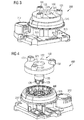
- FIG. 1 shows a perspective exploded view of a manual adjuster for an actuator 100 according to an embodiment of the invention.
- the actuator 100 has a shaft 120, which may also be referred to as a central upper shaft. Namely, the central upper shaft 120 may be engaged with the snap-in projections 126 by means not shown central lower shaft are connected, which in turn is optionally coupled via a transmission with an HVAC valve (not shown).
- the actuator 100 further includes a manual actuator 130, which is a simple handwheel according to the embodiment shown here.
- the handwheel 130 may be manually rotated by an operator using, for example, handles 131.
- the manual actuating element 130 comprises a housing 132, in which two receiving regions 134 are formed. On the housing 132, two snap projections 136 are further formed so that the manual operating member 130 can be snapped into the shaft 120. In this case, the housing and the snap projections 136 are formed so that the manual actuating element 130 can be rotated to the shaft 120.
- a toothing 123 is further formed, which constitutes a part of an overload clutch 140.
- the overload clutch 140 has, in addition to the toothing 123, a coupling element 142 to which a toothing 143 is likewise attached.
- the toothing 143 is at least approximately complementary to the toothing 123, so that the two toothings can engage in one another. Depending on the force with which the two gears 123 and 143 press against each other or abut each other, there is a maximum torque which can be transmitted from the housing 132 to the shaft 120.
- the annular coupling element 142 which has a bulge 144, can be received in the housing 132 of the manual actuating element 130 in a manner safe against rotation. This means that depending on the force with which the two gears 123 and 143 against each other Press, a maximum torque from the manual actuator 130 are transmitted to the shaft 120.
- the force with which the two gears 123 and 143 press against each other can be adjusted by the use of different strong spring elements 148a, 148b, 148c.
- One spring element is in each case introduced into one of the two receiving regions 134 and then abuts on the outside of the coupling element 142 or on a toothed region 143.
- the different spring elements 148a, 148b, 148c differ by different sized cutouts.
- the spring elements 148a, 148b, 148c differ in different local widths, which in turn means that (a) the two spring elements 148c exert a comparatively large spring force on the teeth 143, that (b) the two spring elements 148b have an average spring force exert on the teeth 143 and that (c) the two spring elements 148 a exert a comparatively small spring force on the teeth 143.
- the maximum torque that can be transmitted by means of the overload clutch from the manual operating element 130 to the shaft 120 can be selected.
- the outer dimensions of the spring elements 148a, 148b and 148c which each represent the function of a leaf spring, are at least approximately equal.
- the outer dimensions of the spring elements 148a, 148b and 148c which each represent the function of a leaf spring, are at least approximately equal.
- the actuator 100 can thus be optimally adapted to the respective requirements by a variant assembly by the choice of a suitable replaceable leaf spring 148a, 148b or 148c the maximum transferable torque.
- FIG. 2 shows in a perspective view a slip clutch 250, which is arranged between the shaft 120 and a shaft 290.
- a slip clutch 250 By means of the slip clutch 250, a certain torque can also be transmitted from the shaft 290 to the manual operating element 130. However, this torque is significantly smaller compared to the maximum torque which can be transmitted by means of the overload clutch 140.
- the slip clutch 250 is used to rotate with a rotation of the shaft 290 and the manual operating element 130, if this is otherwise freely rotatable and in particular not locked.
- This has the advantage that an adjusting movement of the drive, which is caused for example by a motor, not shown, and / or by a working spring 260, is indicated by a corresponding rotation of the manual operating element 130.
- the manual actuating element 130 thus represents upon rotation of the shaft a rotating indicator, on which an operator can easily detect an adjusting movement of the drive.
- the shaft 290 is a lower central shaft, which over the in FIG. 1 shown snap projections 126 is connected to the shaft 120.
- the lower central shaft 290 can directly or via a not shown gear with a likewise in FIG. 2 be coupled not shown HVAC valve.
- FIG. 3 shows in a perspective view a part of an actuator 300 with a manual actuation element 130, which has a radially displaceable locking element 370 for locking the manual actuation element 130.
- the radially displaceable locking element 370 points next to the in FIG. 3 recognizable upper part still on a lower part. If the locking element 370 is in a radially outwardly displaced position, the lower part of the locking element 370 engages in a projection of the housing 310 of the actuator 300. Due to the engaging locking element 370, the manual operating element 130 can be locked in terms of its angular position and / or with respect to its axial displacement.
- an engagement opening 371 is formed in the housing 132 of the manual actuating element 130.
- the housing 310 has some vom mit nurser 311, with which the function of the actuator 300 can be checked with the housing closed. Further, the housing 310, which is a one-piece plastic part according to the embodiment shown here, a cover 312 for a motor, not shown. An opening 313 in the housing serves as a cable clamp for the actuator.
- FIG. 4 shows in a perspective exploded view of a part of an actuator 400, which has a arranged between the manual actuating element 130 and the housing 310 latching element 480.
- the latching element is a latching ring 480.
- the latching ring 480 is formed so that upon depression of the manual actuating element 130 in the direction of the housing 310 in the FIGS. 1 and 2 Cams 125 engage in the latching ring 480. Thus, inevitably rotates with a rotational movement of the manual actuating element 130 of the latching ring 480.
- the shaft 120 is further coupled to the manual operating element 130 in the embodiment shown here.
- the latching ring 480 further has on its outer side an asymmetrically toothed surface, which in conjunction with a corresponding inner surface of the housing 310 represents a backstop functionality.
- the manual operating member 130 in the engaged state of the manual operating member 130, the manual operating member 130 can be rotated together with the shaft 120 in only one direction, for example, in the clockwise direction.
- a rotation of the shaft 120 in the opposite direction, for example, counterclockwise, is reliably prevented by the backstop functionality.
- the actuator 400 can remain in its end position after a manual operating intervention in which the manual operating element 130 has been engaged and, if necessary, also turned in one direction.
- the rotational angular position of the shaft 120 can be locked in the manually set position.
- the actuator 500 has a manual actuating element 130, which in turn has a radially displaceable locking element 370 for locking the manual actuating element 130.
- the actuator 500 corresponds to the in FIG. 3 illustrated actuator 300th
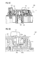
- FIG. 5a shows the actuator 500 in its normal state (Auto Mode). This means that the actuator 500 by means of a motor, not shown, which acts on the shaft 120, operated. In this case, the manual actuating element 130 is in a disengaged or upper position. The manual actuator 130 is apart from the in FIG. 2 shown slip clutch 250 of the shaft 120 decoupled.
- FIG. 5b shows the actuator 500 at the beginning of a manual operator intervention by an operator.
- the operating engagement comprises a push-down of the manual actuating element 130, which in FIG. 5b is illustrated by the vertical arrow.
- a lifting spring 260 is compressed and it is a mechanical coupling between the manual element 130 and the shaft 290 produced.
- the shaft 290 can be rotated by rotation of the manual actuating element 130 in the desired manner. This allows the operator to set a coupled to the shaft 290 valve in any position.
- FIG. 5d shows in an enlarged view how engages in the housing 310 according to the embodiment shown here, the locking element.
- the locking member 370 has an upper part 570a, a connecting rib 570c and a lower part 570b.
- an operator engages the locking member to move it radially outward.
- the lower part 570b engages in corresponding structures of the housing 310 after a corresponding radial movement.
- the manual actuating element 130 is secured against rotational movements as well as against axial displacement.
- FIGS. 6a and 6b each show in a cross-sectional view an actuator 600 having the lifting spring 260.
- the actuator has a latching element arranged between the manual actuating element 130 and the housing, which provides a backstop functionality.
- the actuator 600 corresponds to the in FIG. 4 illustrated actuator 400.
- FIG. 6a shows the actuator 600 in its normal state (Auto Mode). This means that the actuator 600 is operated by means of a motor, not shown, which acts on the shaft 120. In this case, the manual actuating element 130 is in a disengaged or upper position. The manual actuator 130 is apart from the in FIG. 2 shown slip clutch 250 from the shaft 290 decoupled.
- FIG. 6b shows the actuator 600 at the beginning of a manual operation by an operator.
- the operating engagement comprises a push-down of the manual actuating element 130, which in FIG. 6b is illustrated by the vertical arrow.
- the lifting spring 260 is compressed and a mechanical coupling between the manual operating element 130 and the shaft 290 is produced.
- the shaft 290 can be rotated by rotation of the manual actuating element 130 in the desired manner. This allows the operator to set a coupled to the shaft 290 valve in any position.
- the locking of the manual actuating element 130 takes place in that by the manual rotational movement of the manual actuating element 130, the working spring is tensioned.
- the working spring When releasing the manual operating element 130, the working spring then rotates the manual operating element 130 back slightly until a toothing between the in FIG. 4 shown latch member 480 and the housing 310 engages. This creates a high frictional force between the in the FIGS. 1 and 2 illustrated cam 125 and the latch member 480 so that the manual actuator 130 remains in the corresponding axial position. In this position is by the latch 480 a rotation of the manual operating element 130 is prevented.
- both the manual operating element 130 and the shaft 120 remain in a stable (rotational) position.
- the delocking of the manual actuating element takes place according to the exemplary embodiment illustrated here in that the motor, not shown, is operated in such a way that it always first moves in the clockwise direction.
- the cams 125 see FIGS. 1 and 2
- the clamping force of the working spring no longer acts on the manual actuating element 130 and thus the above-mentioned frictional force is considerably reduced.
- the clamping force of the lifting spring is then sufficiently strong to raise the manual operating element 130.
- the motor can then move the shaft freely in both directions of rotation.
- actuators described here can be produced as part of a uniform production process by a suitable variant assembly. This means that within a platform for actuators for HVAC valves variant actuators different actuators with different switching logic can be realized. Furthermore, within the same platform also another so-called. TSR (TÜV Spring Return) actuator can be made, which has already been described above in the introduction to this document.
- FIGS. 1 . 2 . 3 . 5a . 5b . 5c and 5d actuator which is an NSR (Non Spring Return) actuator
- NSR Non Spring Return
- the following functionalities are assigned: (a) indicator for rotating the shaft, (b) switching between engine and Manual operation, (c) locking of the manual actuating element by radially displaceable locking element and (d) overload clutch to avoid damage to drive elements.
- actuator which is a WSR (With Spring Return) actuator
- the following functionalities can be assigned as part of the aforementioned variant assembly: (a) indicator for rotating the shaft, (b) locking of the manual actuating element by the arranged between the manual actuating element and the housing Snap-in element and (c) Overload clutch to prevent damage to drive elements (for example, a motor and / or a transmission).
Landscapes
- Engineering & Computer Science (AREA)
- General Engineering & Computer Science (AREA)
- Mechanical Engineering (AREA)
- Electrically Driven Valve-Operating Means (AREA)
- Mechanical Operated Clutches (AREA)
- Mechanically-Actuated Valves (AREA)
- Transmission Devices (AREA)
Abstract
Description
- Die Erfindung betrifft das technische Gebiet der Heizungs-Lüftungs- und Klimatechnik. Die vorliegende Erfindung betrifft insbesondere einen Stellantrieb für ein Ventil, insbesondere für ein Ventil einer Heizungs-, Lüftungs- und/oder Klimaanlage.
- In vielen Anwendungen in der Heizungs-, Lüftungs- und Klimatechnik (HLK) wird ein Wärmeträgermedium verwendet, um thermische Energie von einem Quellort zu einem Zielort zu übertragen. Die Übertragung von thermischer Energie kann dazu dienen, einen Raum oder einen Bereich innerhalb eines Gebäudes zu heizen. In diesem Fall nimmt das Wärmeträgermedium an dem Quellort Wärmeenergie auf und gibt es nach einem Transport hin zu dem Zielort zumindest teilweise wieder ab. Ebenso kann die Übertragung von thermischer Energie auch dazu dienen, einen Raum oder einen Bereich innerhalb eines Gebäudes zu kühlen. In diesem Fall nimmt das Wärmeüberträgermedium an dem Zielort Wärmeenergie auf und gibt die Wärmeenergie an dem Quellort zumindest teilweise wieder ab.
- Das Wärmeträgermedium kann jedes beliebige Fluid sein. In den meisten Fällen wird Wasser verwendet. Wasser hat den Vorteil, dass es eine hohe spezifische Wärmekapazität hat und damit pro Masseeinheit eine besonders große Wärmemenge transportieren kann.
- Um den Fluss von Wärmeträgermedium in einer HLK-Anlage zu steuern bzw. zu regeln, werden Ventile verwendet, welche auch als HLK-Ventile bezeichnet werden. Mittels eines sog. Absperr- oder Drosselventils kann beispielsweise die Durchflussmenge des Wärmeträgermediums angepasst werden. Mittels eines Mehrwegeventils kann eine geeignete Vermischung des sich auf einem bestimmten Temperaturniveau befindlichen Wärmeträgermediums mit einem sich auf einem anderen Temperaturniveau befindlichen Wärmeträgermedium realisiert und damit eine Anpassung der Wärmeleistung werden.
- HLK-Ventile weisen einen Stellantrieb auf, welcher grundsätzlich mittels verschiedenen Arten von Antriebsmitteln angetrieben bzw. verstellt werden kann. (A) Eine erste Art von Antriebsmittel ist beispielsweise ein Motor, welcher bei einer geeigneten Ansteuerung eine automatische Verstellung des Ventils erlaubt. (B) Eine zweite Antriebsmittel-Art ist eine Handverstelleinrichtung, beispielsweise ein Handrad, mit der/dem eine Bedienperson das betreffende HLK-Ventil manuell verstellen kann. Die Möglichkeit einer Handverstellung kann insbesondere bei einer Inbetriebnahme einer HLK-Anlage von Vorteil sein. (C) Eine dritte Antriebsmittel-Art stellt eine sog. Rücklauffeder dar, welche nach einer Verstellung des HLK-Ventils mit einer Handverstelleinrichtung und/oder einem Motor das HLK-Ventil beispielsweise nach einem Stromausfall automatisch in seine Ausgangsstellung zurück stellt. Ein HLK-Ventil hat typischerweise außer dem o.g. Antriebsmittel (A) zusätzlich noch die o.g. Antriebsmittel (B) und oder (C). Für HLK-Ventile gibt es verschiedene Antriebe, welche nachfolgend kurz erläutert werden:
- NSR (Non Spring Return) Antriebe: Diese Art von VentilAntrieb weist einen Motor und eine Handverstelleinrichtung auf. Eine Rücklauffeder ist nicht vorhanden. NSR-Antriebe werden auch als Nicht-Federrücklauf-Antriebe bezeichnet.
- WSR (With Spring Return) Antriebe: Diese Art von VentilAntrieb weist als mögliche Energiequellen einen Motor, eine Rücklauffeder und eine Handverstelleinrichtung auf. In der Regel wird ein WSR-Antrieb im sog. Auto-Mode mit dem Motor betrieben. Wenn jedoch eine Versorgungsspannung für den Motor ausfällt, schließt die Rücklauffeder das mit dem Antrieb betriebene Ventil. Liegt keine Versorgungsspannung am Motor an, dann kann der WSR-Antrieb manuell geöffnet und in einer beliebigen Position verriegelt werden. Sobald die Versorgungsspannung wieder anliegt, wird der WSR-Antrieb wieder entriegelt und der WSR-Antrieb geht in den Auto-Mode Regelbetrieb über.
- TSR (TÜV Spring Return) Antriebe: Derartige Ventil-Antriebe, welche auch als Federrücklauf-Antriebe bezeichnet werden, diese haben als mögliche Energiequellen einen Motor und eine Rücklauffeder. Infolge von für bestimmte Anwendungen zu beachtende TÜV (Technischer Überwachungs-Verein) Normen, dürfen TSR-Antriebe keine Handverstelleinrichtung aufweisen. Bei einem Stromausfall schließt die Rücklauffeder automatisch das mit dem TSR-Antrieb gekoppelte HLK-Ventil.
- Stellantriebe für HLK-Ventile müssen eine Reihe von technischen Eigenschaften aufweisen und/oder technischen Anforderungen erfüllen, um in der Praxis für HLK-Anlagen eingesetzt zu werden. So muss beispielsweise ein geeigneter Stellantrieb je nach Betriebsmodus eine der drei Energiequellen "Motor", "Rücklauffeder" und "Handversteller" auf ein bewegliches Drosselorgan eines HLK-Ventils schalten können.
- Ferner sollte das Drehmoment, welches mittels der Handverstelleinrichtung auf das Ventil bzw. auf ein Getriebe des Antriebs einwirken kann, durch eine geeignete Überlastkupplung begrenzt werden, damit eine absichtliche und/oder versehentliche Beschädigung von Stellantrieb und/oder Ventil verhindert werden kann. Bekannte Einrichtungen zur Drehmomentbegrenzung für HLK-Ventile sind jedoch technisch relativ aufwändig und zudem unflexibel, da ein vorgegebenes maximal zu übertragendes Drehmoment nicht variiert werden kann.
- Der Erfindung liegt die Aufgabe zugrunde, einen Stellantrieb für ein Ventil zu schaffen, welcher eine einfache und zugleich hinsichtlich des zu übertragenden maximalen Drehmoments flexible Drehmomentbegrenzung aufweist.
- Diese Aufgabe wird gelöst durch die Gegenstände der unabhängigen Patentansprüche. Vorteilhafte Ausführungsformen der vorliegenden Erfindung sind in den abhängigen Ansprüchen beschrieben.
- Gemäß einem ersten Aspekt der Erfindung wird ein Stellantrieb für ein Ventil, insbesondere für ein Ventil einer Heizungs-, Lüftungs- und/oder Klimaanlage, beschrieben. Der beschriebene Stellantrieb weist auf (a) ein Gehäuse, (b) eine Welle, welche zumindest teilweise in dem Gehäuse angeordnet ist und welche direkt oder indirekt mit dem Ventil koppelbar ist, so dass bei einer Drehung der Welle das Ventil verstellbar ist, (c) ein Handbetätigungselement, welches mit der Welle koppelbar ist, und (d) eine Überlastkupplung, welche zwischen dem Handbetätigungselement und der Welle angeordnet ist und welche ein Drehmoment, welches von dem Handbetätigungselement auf die Welle übertragen wird, auf einen vorgegebenen Maximalwert beschränkt. Erfindungsgemäß weist die Überlastkupplung ein Kupplungselement und ein austauschbares Federelement auf, welches das Kupplungselement gegen die Welle drückt, so dass der Maximalwert für das übertragbare Drehmoment von dem austauschbaren Federelement abhängt.
- Dem beschriebenen Stellentrieb liegt die Erkenntnis zugrunde, dass durch eine geeignete Wahl des austauschbaren Federelements das maximale Drehmoment, welches von der Überlastkupplung übertragen werden kann, auf einfache und effiziente Weise an die jeweiligen Anforderungen angepasst werden kann. Dies bedeutet, dass die Auslösemomente der beschriebenen Überlastkupplung abhängig von der Wahl des Federelements auf verschiedene Werte konfektioniert werden können.
- Das austauschbare Federelement kann beispielsweise so dimensioniert sein, dass zum einen eine zuverlässige manuelle Verstellung des Ventil möglich ist und dass zum anderen, wenn sich das Ventil beispielsweise in seiner geöffneten oder geschlossenen Endposition befindet, eine Beschädigung des Ventils oder eines zwischen Ventil und Stellantrieb angeordneten Getriebes auch bei einer kraftvollen Betätigung des Handbetätigungselements zuverlässig verhindert werden kann.
- Der Maximalwert für die Drehmomentübertragung kann insbesondere anhängig von der Form, von der Größe und/oder von dem Material des Federelements sein. Diese Parameter können die Elastizität oder die Spannkraft des austauschbaren Federelements bestimmen. Die Spannkraft kann wiederum die Auflagekraft zwischen dem Kupplungselement und der Welle bestimmen. Selbstverständlich hängt die Spannkraft und damit auch die Auflagekraft bzw. der Auflagedruck zwischen Kupplungselement und Welle auch von der Position des Federelements relativ zu dem Kupplungselement ab.
- Die Kraft- bzw. Drehmomentübertragung zwischen Kupplungselement und Welle kann auf verschiedenen Wechselwirkungen beruhen. So kann zwischen Kupplungselement und Welle eine Reibungskraft auftreten, die von den beiden einander zugewandten Oberflächen von Kupplungselement und Welle abhängt. Zumindest einer der beiden Oberflächen kann beispielsweise eine Gummioberfläche sein, die für eine große Reibung sorgt und damit ein frühzeitiges Durchrutschen der Überlastkupplung verhindert. Die beiden einander zugewandten Oberflächen können auch eine gewisse Rauigkeit aufweisen, welche neben dem Auflagedruck ebenfalls ein wichtiger Parameter für das übertragbare Drehmoment bzw. die übertragbare Kraft darstellt. Ferner kann die Reibung zwischen Kupplungselement und Welle auch durch das Magnetfeld von einem oder von mehreren Magneten, insbesondere Permanentmagneten, verursacht sein, welcher oder welche an der Welle und/oder an dem Kupplungselement angebracht sind.
- Das Handbetätigungselement kann beispielsweise ein einfaches Handrad sein, welches von einer Bedienperson für eine manuelle Verstellung des Ventils betätigt wird.
- Gemäß einem Ausführungsbeispiel der Erfindung ist das austauschbare Federelement an einem Gehäuse des Handbetätigungselements angebracht. Das austauschbare Federelement kann dabei in einer entsprechend geformten Aussparung des Gehäuses eingelegt sein. Dies kann bedeuten, dass das Gehäuse für das austauschbare Federelement eine geeignete Aufnahme darstellt. Während des Zusammenbaus des beschriebenen Stellantriebs kann das austauschbare Federelement beispielsweise einfach in die Aufnahme bzw. die Aussparung eingelegt werden. Nachdem der Stellantrieb dann zusammengebaut ist, kann das Federelement dann in der Aufnahme bzw. Aussparung und damit in seiner vorgesehenen Position fixiert werden. Dies kann automatisch durch andere Komponenten des Stellantriebs erfolgen, so dass zur Fixierung des Federelements kein separater Arbeitsschritt erforderlich ist. Ebenso kann auch ein geeigneter Verriegelungsmechanismus wie beispielsweise ein Sicherungselement dazu verwendet werden, um das Federelement zuverlässig in seiner Aufnahme bzw. Aussparung zu fixieren.
- Bevorzugt ist die Aufnahme in dem Gehäuse derart ausgebildet dass verschiedene Federelemente, welche jeweils eine unterschiedliche Kraft bzw. einen unterschiedlichen Druck auf das Federelement ausüben, aufgenommen werden können. Selbstverständlich können die verschiedenartigen Federelemente auch derart ausgebildet sein, dass sie gleiche oder zumindest ähnliche Außenabmessungen aufweisen und so auf einfache Weise eine anwendungsspezifische Variantenbestückung des Stellantriebs mit verschiedenen, unterschiedlich starken Federelementen erleichtern.
- Gemäß einem weiteren Ausführungsbeispiel der Erfindung weist das austauschbare Federelement die Form eines länglichen Streifens auf. Ferner ist das austauschbare Federelement zumindest teilweise aus einem elastischen Material, insbesondere aus Metall, hergestellt. Das austauschbare Federelement kann dabei eine einfache Blattfeder darstellen.
- Die beschriebene Formgebung kann den Vorteil haben, dass das austauschbare Federelement auf besonders einfache Weise hergestellt werden kann. Ferner kann das derart geformte austauschbare Federelement problemlos an dem o.g. Gehäuse angebracht werden.
- Es wird darauf hingewiesen, dass unterschiedliche starke austauschbare Federelemente bzw. Blattfedern auf einfache Weise dadurch hergestellt werden können, dass ausgehend von einem elastischen Ausgangsstreifen verschieden große Ausschnitte aus- bzw. abgeschnitten werden. Auf diese Weise bleibt die äußere Form des Streifens im Wesentlichen erhalten. Infolge von unterschiedlichen lokalen Breiten des Streifens kann, von außen leicht ersichtlich, eine individuelle Federhärte eingestellt werden.
- Gemäß einem weiteren Ausführungsbeispiel der Erfindung weist das Kupplungselement eine erste Verzahnung und die Welle eine zweite Verzahnung auf. Dabei greifen die erste Verzahnung und die zweite Verzahnung zumindest teilweise ineinander. Dies hat den Vorteil, dass die Überlastkupplung innerhalb eines kleinen Bauraumes realisiert werden kann und trotzdem in der Lage ist, bei Bedarf in Verbindung mit einem starken Federelement hohe Drehmomente zu übertragen.
- Im zusammengebauten Zustand des Stellantriebs kann das Kupplungselement die Welle zumindest teilweise umgeben, wobei die erste Verzahnung des Kupplungselements und die zweite Verzahnung der Welle zumindest teilweise ineinander greifen.
- Die beschriebene eine Verzahnung aufweisende Überlastkupplung kann auf einfache Weise dahingehend realisiert werden, dass das jeweilige Auslösemoment innerhalb eines mehr oder weniger genau vorgegebenen Toleranzbereiches liegt. Ferner kann einer Bedienperson im Falle einer Auslösung bzw. eines Öffnens der Überlastkupplung ein gut spürbares Feedback gegeben werden. So kann die Bedienperson das Auslösen der Überlastkupplung beispielsweise durch ein durch eine Relativbewegung der beiden Verzahnungen verursachtes Vibrieren spüren und/oder durch ein entsprechendes Vibrations- oder Ratschengeräusch hören.
- Gemäß einem weiteren Ausführungsbeispiel der Erfindung weist der Stellantrieb ferner einen Motor auf, welcher mit der Welle koppelbar ist.
- Durch eine geeignete elektrische Ansteuerung des Motors kann der Stellantrieb und damit auch das von dem Stellantrieb bewegte Ventil automatisch in eine gewünschte Zielposition gebracht werden.
- Gemäß einem weiteren Ausführungsbeispiel der Erfindung weist der Stellantrieb ferner eine Arbeitsfeder auf, welche mit der Welle koppelbar ist.
- Die Arbeitsfeder kann dazu dienen, dass die Stelleinrichtung bei einem Loslassen des Handbetätigungselements und/oder bei einem Ausfall der Spannungsversorgung selbstständig in eine Vorzugsstellung überführt wird. Dies kann insbesondere für sicherheitsrelevante Anwendungen bedeutend sein.
- Gemäß einem weiteren Ausführungsbeispiel der Erfindung weist der Stellantrieb ferner eine weitere Welle, welche direkt oder indirekt mit dem Ventil koppelbar ist, und einen Koppelmechanismus auf, welcher zwischen der weiteren Welle und der Welle angeordnet ist. Der Koppelmechanismus ist derart eingerichtet, dass (a) in einem ersten Betriebszustand das Handbetätigungselement von der weiteren Welle entkoppelt ist und (b) in einem zweiten Betriebszustand das Handbetätigungselement mit der weiteren Welle gekoppelt ist.
- Der Koppelmechanismus kann beispielsweise eine Eingreifkupplung sein, bei der die weitere Welle, welche auch als untere Welle bezeichnet werden kann, und die Welle bei nicht ausgelöster Überlastkupplung im zweiten Betriebszustand starr miteinander verbunden sind und im ersten Betriebszustand zumindest teilweise voneinander entkoppelt sind. Die Kopplung, d.h. ein Übergang vom ersten in den zweiten Betriebszustand, kann bevorzugt durch ein Ineinandergreifen von verschiedenen Komponenten des Koppelmechanismus erfolgen. Eine Entkopplung, d.h. ein Übergang vom zweiten in den ersten Betriebszustand, kann durch ein Voneinander-Lösen der verschiedenen Komponenten erfolgen. Somit kann der erste Betriebszustand auch als Freilaufzustand und der zweite Betriebszustand auch als Koppelzustand bezeichnet werden.
- Der erste Betriebszustand kann auch als normaler Betriebszustand bezeichnet werden, da im normalen Betrieb des Stellantriebs eine manuelle Betätigung bzw. Ventilverstellung nicht erforderlich ist. Der zweite Betriebszustand kann beispielsweise dann eingestellt werden, wenn Wartungsarbeiten und/oder Umbauten an einer HLK-Anlage erforderlich sind und auf einfache und effiziente Weise durchgeführt werden sollen.
- Gemäß einem weiteren Ausführungsbeispiel der Erfindung liegt einer der beiden Betriebszustände dann vor, wenn sich die weitere Welle in Bezug zu der Welle in einer ausgerückten Position befindet. Ferner liegt der andere der beiden Betriebszustände dann vor, wenn sich die weitere Welle in Bezug zu der Welle in einer eingerückten Position befindet. Dies kann den Vorteil haben, dass der Stellantrieb durch einen besonders einfachen Bedieneingriff von dem ersten Betriebszustand in den zweiten Betriebszustand und umgekehrt überführt werden kann.
- Bevorzugt liegt der erste Betriebszustand bzw. der Freilaufzustand vor, wenn das Handbetätigungselement in Bezug zu zumindest einer anderen Komponente des Stellantriebs ausgerückt bzw. herausgezogen ist. Entsprechend liegt der zweite Betriebszustand bzw. der Koppelzustand vor, wenn das Handbetätigungselement in Bezug zu der zumindest einen anderen Komponente eingerückt bzw. hineingedrückt ist.
- Der eingerückte Zustand kann auch als "Hand-Mode Push" Zustand bezeichnet werden. Beim Einrücken des Handbetätigungselements wird dieses nämlich in bzw. an die Welle gekoppelt. Gleichzeitig kann ein ggf. vorhandener Motor, welcher ebenfalls die Welle antreiben kann, von der Welle abgekoppelt werden. Dann kann der Stellantrieb bzw. ein mit dem Stellantrieb betriebenes Ventil durch eine einfache Bewegung des Handbetätigungselements verstellt werden, ohne dass dabei eine versehentliche Beschädigung des Motors oder eines mit dem Motor verbundenen Getriebes zu besorgen wäre.
- Gemäß einem weiteren Ausführungsbeispiel der Erfindung weist der Stellantrieb ferner eine Rutschkupplung auf, welche ebenfalls zwischen der weiteren Welle und der Welle angeordnet ist und welche derart eingerichtet ist, dass sich, auch wenn sich der Koppelmechanismus in dem ersten Betriebszustand befindet, bei einer Drehung der weiteren Welle die Welle dreht.
- Dies bedeutet, dass das mit der Welle gekoppelte Handbetätigungselement nicht nur zum aktiven manuelle Antreiben der Welle verwendet werden kann sondern dass das Handbetätigungselement auch als Anzeigeeinrichtung für eine Drehung der weiteren Welle fungieren kann, welche mittels einer eigenen Drehung einer Bedienperson anzeigt, dass die weitere Welle durch eine andere Energiequelle gedreht wird.
- Durch die Rutschkupplung, welche typischerweise lediglich ein sehr kleines Drehmoment von der weiteren Welle auf die Welle übertragen kann, stellt das mit der Welle gekoppelte und ansonsten zumindest annähernd freilaufende Handbetätigungselement einen Indikator dar, welche eine Drehung der Welle durch eine eigene nicht von einer Bedienperson veranlasste Drehung anzeigt.
- Die andere Energiequelle kann beispielsweise ein Motor und/oder eine Arbeitsfeder sein, welche in bekannter weise die Welle eines Stellantriebes für ein HLK-Ventil antreiben kann bzw. können.
- Bevorzugt kann die Rutschkupplung im Vergleich zu der oben beschriebenen Überlastkupplung nur ein sehr kleines Drehmoment übertragen. Ein zumindest annähernd frei laufendes Handbetätigungselement kann daher über die Rutschkupplung in eine Drehbewegung versetzt werden. Falls jedoch das Handbetätigungselement von außen an eine Drehbewegung gehindert werden sollte, dann kann die Rutschkupplung zuverlässig eine Störung des Stellantriebs verhindern.
- Gemäß einem weiteren Ausführungsbeispiel der Erfindung weist der Stellantrieb ferner ein Verriegelungselement auf, welches an dem Handbetätigungselement angebracht ist und welches derart ausgebildet ist, dass bei einer Aktivierung des Verriegelungselements ein Verstellen des Handbetätigungselements relativ zu dem Gehäuse verhindert ist. Dies hat den Vorteil, dass eine ungewollte Bewegung des Handbetätigungselements auf einfache und zuverlässige Weise verhindert werden kann.
- Das Verriegelungselement kann beispielsweise für Wartungsarbeiten und/oder für Umbauarbeiten an einer HLK-Anlage aktiviert werden. Auch bei einer bestehenden elektrischen Kabelverbindung zu dem Motor (bei einer beliebigen elektrischen Motoransteuerung) kann ein ungewolltes Verstellen des Stellantriebs verhindert werden. Ein aufwendiges Lösen von elektrischen Verbindungen, wie es bei bekannten HLK-Stellantrieben im Wartungsfall erforderlich ist, ist bei dem hier beschriebenen Stellantrieb nicht mehr nötig. Damit können Wartungs-und/oder Umbauarbeiten deutlich zügiger durchgeführt werden.
- Gemäß einem weiteren Ausführungsbeispiel der Erfindung ist das Verriegelungselement in Bezug zu der Längsachse der Welle radial verschiebbar. Dabei kann das Verriegelungselement mit dem Gehäuse des Stellantriebs auf geeignete Weise in Eingriff gebracht werden.
- In diesem Zusammenhang wird zur Sicherheit darauf hingewiesen, dass das hier genannte Gehäuse des Stellantriebs verschieden ist von dem bereits weiter oben erwähnten Gehäuse des Handbetätigungselements.
- Die Aktivierung des Verriegelungselements mittels einer radialen Verschiebung hat den Vorteil, dass das Handbetätigungselement von einer Bedienperson durch eine einfache Handbewegung, ggf. sogar lediglich durch die Bewegung eines einzigen Fingers, arretiert werden kann.
- Der Eingriff zwischen Verriegelungselement und Gehäuse verhindert eine unerwünschte Drehung des Handbetätigungselements.
- Ferner kann, das Verriegelungselement auch in Bezug zu der Welle noch in axialer Richtung mit dem Gehäuse in Eingriff gebracht werden. Dies kann beispielsweise durch ein Untergreifen an einem Vorsprung des Gehäuses des Stellantriebs erfolgen. Dadurch kann ein Verschieben des Handbetätigungselements in axialer Richtung verhindert werden. Insbesondere kann ein versehentlicher Übergang des Handbetätigungselements von dem ersten Betriebszustand zu dem zweiten Betriebszustand und umgekehrt verhindert werden.
- Es wird ausdrücklich darauf hingewiesen, dass das hier beschriebene Verriegelungselement sowohl für den genannten radialen Eingriff als auch gleichzeitig für den genannten axialen Eingriff verwendet werden kann. Dadurch kann auf einfache Weise eine Arretierung des Handbetätigungselements in Bezug auf alle möglichen Bewegungsrichtungen erreicht werden.
- Es wird ferner darauf hingewiesen, dass, sofern das Handbetätigungselement nicht eingerückt ist oder nicht durch das Verriegelungselement in der eingerückten Position gehalten wird, die Hubfeder das Handbetätigungselement automatisch in eine Position schieben kann, in der sich der Stellantrieb in einem sog. Auto-Mode befindet. Dabei bedeutet Auto-Mode, dass der Stellantrieb mit einem Motor betrieben wird.
- Gemäß einem weiteren Ausführungsbeispiel der Erfindung weist der Stellantrieb ferner ein Einrastelement auf, welches zwischen dem Handbetätigungselement und dem Gehäuse angeordnet ist und welches einen ersten Einrastbereich und einen zweiten Einrastbereich aufweist. Der erste Einrastbereich ist dabei eingerichtet in eine erste Oberflächenkontur des Handbetätigungselementes einzugreifen. Entsprechend ist der zweite Einrastbereich eingerichtet in eine zweite Oberflächenkontur des Gehäuses einzugreifen.
- Die erste Oberflächenkontur des Handbetätigungselements kann beispielsweise mehrere Vorsprünge aufweisen, die von einem zentralen Schaft des Handbetätigungselements radial nach außen abstehen. Die Vorsprünge können beispielsweise Zapfen, Pins, Nocken oder jede andere Art von Erhebungen sein, welche für einen mechanischen Eingriff zwischen Handbetätigungselement und Einrastelement in Frage kommen. Bei einem Eingriff von dem ersten Einrastbereich in die erste Oberflächenkontur ist beispielsweise gewährleistet, dass sich bei einer Drehung des Handbetätigungselementes auch das Einrastelement mit dem Handbetätigungselement dreht. Selbstverständlich ist dies nur möglich, wenn nicht gleichzeitig der zweite Einrastbereich in die zweite an dem Gehäuse ausgebildete Oberflächenkontur eingreift.
- Die erste Oberflächenkontur und der erste Einrastbereich weisen bevorzugt eine zueinander komplementäre Form auf, so dass ein zuverlässiges Eingreifen möglich ist. Das gleiche kann für die Formgebung des zweiten Einrastbereiches und der zweiten Oberflächenkontur gelten.
- Gemäß einem weiteren Ausführungsbeispiel der Erfindung ist das Einrastelement derart ausgebildet, dass (a) die Möglichkeit des Eingreifens des ersten Einrastbereiches in die erste Oberflächenkontur und/oder (b) die Möglichkeit des Eingreifens des zweiten Einrastbereiches in die zweite Oberflächenkontur davon abhängt, in welcher Position sich das Handbetätigungselement befindet. Dies kann bedeuten, dass die Position oder die Stellung des Handbetätigungselementes einen Einfluss auf die Wirkung des Einrastelementes hat.
- Beispielsweise kann die Wirkung des Einrastelementes deaktiviert oder verhindert werden, wenn sich das Handbetätigungselement in Bezug zu der Welle in einer ausgerückten Position befindet. In Gegensatz dazu kann die oben beschriebene Wirkung des Einrastelementes aktiviert oder ermöglicht werden, wenn sich das Handbetätigungselement in Bezug zu der Welle in einer eingerückten Position befindet. Die Begriffe "ausgerückte Position" und "eingerückte Position" wurden bereits weiter oben in diesem Dokument genau beschrieben und werden deshalb an dieser Stelle nicht noch einmal im Detail erläutert.
- Eine Bedienperson kann ggf. durch ein einfaches Einrücken oder Drücken des Handbetätigungselementes die Wirkung des Einrastelementes aktivieren bzw. ermöglichen und durch ein Ausrücken oder Wegziehen des Handbetätigungselementes die Wirkung des Einrastelementes deaktivieren bzw. unterbinden. Dies bedeutet, dass das Einrastelement in der eingerückten Position des Handbetätigungselementes eine Bewegung, insbesondere eine Drehung im Gegenuhrzeigersinn, des Handbetätigungselementes verhindert. In der ausgerückten Position liegt dann keine Sperrwirkung für eine Bewegung, insbesondere für eine Drehung, des Handbetätigungselementes vor.
- Gemäß einem weiteren Ausführungsbeispiel der Erfindung ist der zweite Einrastbereich des Einrastelementes und/oder die zweite Oberflächenkontur des Gehäuses derart geformt, dass das Einrastelement in Bezug zu dem Gehäuse eine Rücklaufsperren-Funktionalität aufweist. Die beschriebene Rücklaufsperren-Funktionalität kann den Vorteil aufweisen, dass nach einer Betätigung des Handbetätigungselementes ein unerwünschter Rücklauf des Handbetätigungselementes insbesondere durch die Federkraft einer Arbeitsfeder auf einfache Weise verhindert werden kann.
- Die Rücklaufsperren-Funktionalität kann beispielsweise auf dem Prinzip einer sog. Sperrklinke basieren, bei der der zweite Einrastbereich und/oder die zweite Oberflächenkontur eine Verzahnung mit asymmetrischen Verzahnungsflanken aufweist.
- Es wird darauf hingewiesen, dass die Rücklaufsperren-Funktionalität derart ausgebildet sein kann, dass die Rücklaufsperre durch ein leichtes Bewegen, insbesondere durch eine kleine Drehung, des Handbetätigungselementes in einer vorgegebene Richtung deaktiviert werden kann. Eine derartige deaktivierende Bewegung des Handbetätigungselementes kann beispielsweise durch einen Motor des Stellantriebs erfolgen welcher mit der Welle gekoppelt ist. Anschaulich gesprochen kann durch das Bewegen des Handbetätigungselementes in eine vorgegebene Richtung das Einrastelement aus Widerhaken gelöst werden, die an dem jeweiligen Einrastbereich und/oder an der jeweiligen Oberflächenkontur ausgebildet sind.
- Beispielsweise kann eine Drehung des Handbetätigungselementes in (gegen) Uhrzeigerrichtung mit lediglich einem geringen Widerstand verknüpft sein. Bei dieser Drehung kann dann eine Bedienperson ein Vibrieren spüren und/oder durch ein entsprechendes Vibrations- oder Ratschengeräusch hören. Im Gegensatz dazu ist eine Drehung gegen (in) Uhrzeigerrichtung infolge der beschriebenen Sperrklinkenwirkung unterbunden.
- Gemäß einem weiteren Ausführungsbeispiel der Erfindung weist der Stellantrieb ferner eine Hubfeder auf, welche an dem Handbetätigungselement angreift und eine Kraft entlang der axialen Richtung der Welle auf das Handbetätigungselement ausübt.
- Um die Kraftwirkung auf das Handbetätigungselement ausüben zu können, muss die Hubfeder zusätzlich noch an einer anderen Komponente des Stellantriebs angreifen. Diese andere Komponente kann beispielsweise die Welle sein. Bevorzugt drückt die Hubfeder die o.g. Welle, welche einen oberen zentralen Schaft darstellt, von der o.g. weiteren Welle, welche einen unteren zentralen Schaft darstellt, weg.
- Die beschriebene Hubfeder hat den Vorteil, dass das Handbetätigungselement durch einen einfachen Bedieneingriff einer Bedienperson in verschiedene in Bezug zu der Welle axiale Positionen gebracht werden kann. Die unterschiedlichen axialen Positionen können beispielsweise die oben beschriebenen und mit verschiedenen Betriebszuständen des Handbetätigungselementes verknüpften Positionen, insbesondere die ausgerückte Position und die eingerückte Position, sein.
- Es wird darauf hingewiesen, dass gemäß einem bevorzugten Ausführungsbeispiel der Erfindung das Einrastelement durch eine Kombination einer Verschiebebewegung des Handbetätigungselements entlang der Achsrichtung und einer Drehbewegung im Uhrzeigersinn des o.g. Einrastelementes aktiviert werden kann. So kann beispielsweise in einer arretierten Stellung (Lock Zustand) das Einrastelement ein unerwünschtes Verstellen des Antriebs durch eine Arbeitsfeder des Stellantriebs verhindern. Dadurch kann nach einem manuellen Bedieneingriff, mit dem das Handbetätigungselement in eine Zielstellung gebracht worden ist, ein unerwünschtes Verstellen des beschriebenen Stellantriebs verhindert werden.
- Insbesondere kann das Arretieren des Handbetätigungselementes dadurch erfolgen, dass bei einer manuellen Drehbewegung des Handbetätigungselementes eine vergleichsweise starke Arbeitsfeder gespannt wird. Beim Loslassen des Handbetätigungselementes dreht die Arbeitsfeder dann das Handbetätigungselement etwas zurück, bis eine nächste Verzahnung zwischen dem Einrastelement und dem Gehäuse greift. Da die Arbeitsfeder typischerweise vergleichsweise stark ist, entsteht dabei eine hohe Reibkraft zwischen den oben beschriebenen Vorsprüngen des Handbetätigungselementes und dem Einrastelement. Diese Reibkraft kann von der wesentlich schwächeren Hubfeder nicht überwunden werden, so dass das Handbetätigungselement in der entsprechenden Axialposition verbleibt. In dieser Position ist durch das Einrastelement eine Drehung des Handbetätigungselementes unterbunden. Dadurch verbleibt trotz der Kraftwirkung der Arbeitsfeder sowohl das Handbetätigungselement als auch die Welle in einer stabilen (Dreh) Position.
- Das Lösen (delock) des Handbetätigungselementes kann bevorzugt wie folgt erfolgen: Der Motor wird so betrieben, dass er sich immer zunächst in eine Richtung (z.b. eine Öffnungsrichtung des Ventils) bewegt. Dadurch entriegeln sich die oben beschriebenen Vorsprünge des Handbetätigungselementes und der erste Einrastbereich des Einrastelementes. Dies hat zur Folge, dass die Spannkraft der Arbeitsfeder nicht mehr auf das Handbetätigungselement einwirkt und die oben beschriebene Reibkraft entsprechend reduziert wird. Damit kann die Spannkraft der Hubfeder dann ausreichend stark werden, um das Handbetätigungselement anzuheben. Danach kann der Motor dann die Welle frei und insbesondere ungestört von dem Handbetätigungselement bewegen.
- Es wird darauf hingewiesen, dass Ausführungsformen der Erfindung mit Bezug auf unterschiedliche Gegenstände beschrieben wurden. Dem Fachmann wird jedoch bei der Lektüre dieser Anmeldung sofort klar werden, dass, sofern nicht explizit anders angegeben, zusätzlich zu einer Kombination von Merkmalen, die zu einem Gegenstand gehören, auch eine beliebige Kombination von Merkmalen möglich ist, die zu unterschiedlichen Gegenständen gehören.
- Weitere Vorteile und Merkmale der vorliegenden Erfindung ergeben sich aus der folgenden beispielhaften Beschreibung derzeit bevorzugter Ausführungsformen.
-
Figur 1 zeigt in einer perspektivischen Explosionsdarstellung einen Handversteller für einen Stellantrieb und insbesondere eine Überlastkupplung des Handverstellers, welche mit unterschiedlich starken Federelementen bestückt werden kann. -
Figur 2 zeigt in einer perspektivischen Darstellung eine Rutschkupplung, welche bei einer Drehung der Welle, die durch einen Motor und/oder durch eine Arbeitsfeder veranlasst ist, eine Drehung des an sich ausgekuppelten Handbetätigungselementes als Anzeigeeinrichtung für die Drehung der Welle bewirkt. -
Figur 3 zeigt in einer perspektivischen Darstellung einen Teil eines Stellantriebs mit einem Handbetätigungselement, welches ein radial verschiebbares Verriegelungselement für eine Arretierung des Handbetätigungselementes aufweist. -
Figur 4 zeigt in einer perspektivischen Explosionsdarstellung einen Teil eines Stellantriebs, welcher ein zwischen dem Handbetätigungselement und dem Gehäuse angeordnetes Einrastelement aufweist, welches eine Rücklaufsperren-Funktionalität bereitstellt. -
Figur 5a, 5b ,5c und 5d zeigen jeweils in einer Querschnittsdarstellung einen keine Arbeitsfeder aufweisenden Stellantrieb mit einem Handbetätigungselement, welches ein radial verschiebbares Verriegelungselement für eine Arretierung des Handbetätigungselementes aufweist. -
Figur 6a und 6b zeigen jeweils in einer Querschnittsdarstellung einen eine nicht dargestellte Arbeitsfeder aufweisenden Stellantrieb, welcher ein zwischen dem Handbetätigungselement und dem Gehäuse angeordnetes Einrastelement aufweist, welches eine Rücklaufsperren-Funktionalität bereitstellt. - Es wird darauf hingewiesen, dass Merkmale bzw. Komponenten von unterschiedlichen Ausführungsformen, die mit den entsprechenden Merkmalen bzw. Komponenten der Ausführungsform nach gleich oder zumindest funktionsgleich sind, mit den gleichen Bezugszeichen oder mit einem anderen Bezugszeichen versehen sind, welches sich lediglich in seiner ersten ziffer von dem Bezugszeichen einer entsprechenden Komponente unterscheidet. Zur Vermeidung von unnötigen Wiederholungen werden bereits anhand einer vorher beschriebenen Ausführungsform erläuterte Merkmale bzw. Komponenten an späterer Stelle nicht mehr im Detail erläutert.
- Ferner wird darauf hingewiesen, dass die nachfolgend beschriebenen Ausführungsformen lediglich eine beschränkte Auswahl an möglichen Ausführungsvarianten der Erfindung darstellen. Insbesondere ist es möglich, die Merkmale einzelner Ausführungsformen in geeigneter weise miteinander zu kombinieren, so dass für den Fachmann mit den hier explizit dargestellten Ausführungsvarianten eine Vielzahl von verschiedenen Ausführungsformen als offensichtlich offenbart anzusehen sind.
-
Figur 1 zeigt in einer perspektivischen Explosionsdarstellung einen Handversteller für einen Stellantrieb 100 gemäß einem Ausführungsbeispiel der Erfindung. Der Stellantrieb 100 weist eine Welle 120 auf, welche auch als zentraler oberer Schaft bezeichnet werden kann. Der zentrale obere Schaft 120 kann nämlich über die Schnappvorsprünge 126 mit einem nicht dargestellten zentralen unteren Schaft verbunden werden, welcher wiederum ggf. über ein Getriebe mit einem HLK-Ventil (nicht dargestellt) gekoppelt ist. - Der Stellantrieb 100 weist ferner ein Handbetätigungselement 130 auf, welches gemäß dem hier dargestellten Ausführungsbeispiel ein einfaches Handrad ist. Das Handrad 130 kann von einer Bedienperson beispielsweise unter Verwendung der Griffe 131 manuell gedreht werden. Das Handbetätigungselement 130 umfasst ein Gehäuse 132, in dem zwei Aufnahmebereiche 134 ausgebildet sind. An dem Gehäuse 132 sind ferner zwei Schnappvorsprünge 136 ausgebildet, so dass das Handbetätigungselement 130 in die Welle 120 eingeschnappt werden kann. Dabei sind das Gehäuse und die Schnappvorsprünge 136 so ausgebildet, dass das Handbetätigungselement 130 zur Welle 120 verdreht werden kann.
- An der Welle 120 sind mehrere radial abstehende Nocken 125 ausgebildet oder angebracht, deren Funktion nachfolgend noch genauer erklärt wird. An der Welle 120 ist ferner eine Verzahnung 123 ausgebildet, welche einen Teil einer Überlastkupplung 140 darstellt. Die Überlastkupplung 140 weist neben der Verzahnung 123 ein Kupplungselement 142 auf, an dem ebenfalls eine Verzahnung 143 angebracht ist. Gemäß dem hier dargestellten Ausführungsbeispiel ist die Verzahnung 143 mit der Verzahnung 123 zumindest annähernd komplementär, so dass die beiden Verzahnungen ineinander greifen können. Abhängig von der Kraft, mit der die beiden Verzahnungen 123 und 143 gegeneinander drücken bzw. aneinander anliegen, ergibt sich ein maximales Drehmoment, welches vom Gehäuse 132 auf die Welle 120 übertragen werden kann.
- Wie aus
Figur 1 ersichtlich, kann das ringförmige Kupplungselement 142, welches eine Ausbuchtung 144 aufweist, in dem Gehäuse 132 des Handbetätigungselementes 130 drehsicher aufgenommen werden. Dies bedeutet, dass abhängig von der Kraft, mit der die beiden Verzahnungen 123 und 143 gegeneinander drücken, ein maximales Drehmoment von dem Handbetätigungselement 130 auf die Welle 120 übertragen werden. - Gemäß dem hier dargestellten Ausführungsbeispiel kann die Kraft, mit der die beiden Verzahnungen 123 und 143 gegeneinander drücken, durch die Verwendung von verschieden starken Federelementen 148a, 148b, 148c eingestellt werden. Jeweils ein Federelement wird nämlich in einen der beiden Aufnahmebereiche 134 eingebracht und liegt dann von außen an dem Kupplungselement 142 bzw. an einem Verzahnungsbereich 143 an. Wie aus
Figur 1 ersichtlich, unterscheiden sich die unterschiedlichen Federelemente 148a, 148b, 148c durch unterschiedlich große Ausschnitte. Demzufolge unterscheiden sich die Federelemente 148a, 148b, 148c durch unterschiedliche lokale Breiten, was wiederum zur Folge hat, dass (a) die beiden Federelemente 148c eine vergleichsweise große Federkraft auf die Verzahnungen 143 ausüben, dass (b) die beiden Federelemente 148b eine mittlere Federkraft auf die Verzahnungen 143 ausüben und dass (c) die beiden Federelemente 148a eine vergleichsweise kleine Federkraft auf die Verzahnungen 143 ausüben. Damit kann abhängig von der Wahl der Federelemente das maximale Drehmoment, welches mittels der Überlastkupplung von dem Handbetätigungselement 130 auf die Welle 120 übertragen werden kann, gewählt werden. - Es wird darauf hingewiesen, dass gemäß dem hier dargestellten Ausführungsbeispiel die äußeren Abmessungen der Federelemente 148a, 148b und 148c, welche jeweils die Funktion einer Blattfeder darstellen, zumindest annähernd gleich sind. Bei der Herstellung des Stellantriebs 100 kann somit durch eine Variantenbestückung durch die Wahl einer geeigneten austauschbaren Blattfeder 148a, 148b oder 148c das maximal übertragbare Drehmoment an die jeweiligen Anforderungen optimal angepasst werden.
-
Figur 2 zeigt in einer perspektivischen Darstellung eine Rutschkupplung 250, welche zwischen der Welle 120 und einer Welle 290 angeordnet ist. Mittels der Rutschkupplung 250 kann ebenfalls ein gewisses Drehmoment von der Welle 290 auf das Handbetätigungselement 130 übertragen werden. Dieses Drehmoment ist jedoch im Vergleich zu dem maximalen Drehmoment, welches mittels der Überlastkupplung 140 übertragen werden kann, deutlich kleiner. - Gemäß dem hier dargestellten Ausführungsbeispiel wird die Rutschkupplung 250 dazu verwendet, bei einer Drehung der Welle 290 auch das Handbetätigungselement 130 zu drehen, sofern dieses ansonsten frei drehbar und insbesondere nicht arretiert ist. Dies hat den Vorteil, dass eine Verstellbewegung des Antriebs, die beispielsweise durch einen nicht dargestellten Motor und/oder durch eine Arbeitsfeder 260 veranlasst ist, durch eine entsprechende Drehung des Handbetätigungselementes 130 angezeigt wird. Das Handbetätigungselement 130 stellt bei einer Drehung der Welle somit einen sich drehenden Indikator dar, an dem eine Bedienperson eine Verstellbewegung des Antriebs auf einfache Weise erkennen kann.
- Gemäß dem hier dargestellten Ausführungsbeispiel ist die Welle 290 ein unterer zentraler Schaft, der über die in
Figur 1 dargestellten Schnappvorsprünge 126 mit der Welle 120 verbunden ist. Der untere zentrale Schaft 290 kann direkt oder über ein nicht dargestelltes Getriebe mit einem ebenfalls inFigur 2 nicht dargestellten HLK-Ventil gekoppelt sein. -
Figur 3 zeigt in einer perspektivischen Darstellung einen Teil eines Stellantriebs 300 mit einem Handbetätigungselement 130, welches ein radial verschiebbares Verriegelungselement 370 für eine Arretierung des Handbetätigungselementes 130 aufweist. Das radial verschiebbare Verriegelungselement 370 weist neben dem inFigur 3 erkennbaren oberen Teil noch einen unteren Teil auf. Sofern sich das Verriegelungselement 370 in einer radial nach außen verschobenen Position befindet, greift der untere Teil des Verriegelungselementes 370 in einen Vorsprung des Gehäuses 310 des Stellantriebs 300 ein. Durch das eingreifende Verriegelungselement 370 kann das Handbetätigungselement 130 hinsichtlich seiner Drehwinkellage und/oder hinsichtlich seiner axialen Verschiebung arretiert werden. - Um bei Bedarf das Verriegelungselement 370 auf einfache Weise radial verschieben zu können, ist in dem Gehäuse 132 des Handbetätigungselementes 130 eine Eingriffsöffnung 371 ausgebildet. Dadurch kann eine Bedienperson durch einen Eingriff mit lediglich einem Finger auf einfache Weise das Verriegelungselement 370 radial nach außen verschieben.
- Gemäß dem hier dargestellten Ausführungsbeispiel weist das Gehäuse 310 einige Prüfdurchgriffe 311 auf, mit denen bei geschlossenem Gehäuse die Funktion des Stellantriebs 300 überprüft werden kann. Ferner weist das Gehäuse 310, welches gemäß dem hier dargestellten Ausführungsbeispiel ein einstückiges Kunststoffteil ist, eine Abdeckung 312 für einen nicht dargestellten Motor auf. Ein Durchbruch 313 in dem Gehäuse dient einer Kabelklemme für den Stellantrieb.
-
Figur 4 zeigt in einer perspektivischen Explosionsdarstellung einen Teil eines Stellantriebs 400, welcher ein zwischen dem Handbetätigungselement 130 und dem Gehäuse 310 angeordnetes Einrastelement 480 aufweist. Gemäß dem hier dargestellten Ausführungsbeispiel ist das Einrastelement eine Einrastring 480. Der Einrastring 480 ist so ausgeformt, dass bei einem Herunterdrücken des Handbetätigungselementes 130 in Richtung des Gehäuses 310 die in denFiguren 1 und2 dargestellten Nocken 125 in den Einrastring 480 eingreifen. Somit dreht sich zwangsläufig bei einer Drehbewegung des Handbetätigungselements 130 der Einrastring 480 mit. In dem heruntergedrückten bzw. eingerückten Zustand ist bei dem hier dargestellten Ausführungsbeispiel ferner die welle 120 mit dem Handbetätigungselement 130 gekuppelt. Der Einrastring 480 weist ferner an seiner Außenseite eine asymmetrisch gezahnte Oberfläche auf, welche in Verbindung mit einer entsprechenden Innenoberfläche des Gehäuses 310 eine Rücklaufsperren-Funktionalität darstellt. Somit kann in dem eingerückten Zustand des Handbetätigungselementes 130 das Handbetätigungselement 130 zusammen mit der Welle 120 lediglich in eine Richtung, beispielsweise in Uhrzeigerrichtung, gedreht werden. Eine Drehung der Welle 120 in die entgegengesetzte Richtung, beispielsweise entgegen des Uhrzeigersinns, wird durch die Rücklaufsperren-Funktionalität zuverlässig verhindert. Auf diese Weise kann auch der Stellantrieb 400 nach einem manuellen Bedieneingriff, bei dem das Handbetätigungselement 130 eingerückt und ggf. zudem in eine Richtung gedreht wurde, in seiner Endposition verharren. Damit kann auch die Drehwinkelposition der Welle 120 in der manuell eingestellten Stellung arretiert werden. - Die
Figuren 5a, 5b ,5c und 5d zeigen jeweils in einer Querschnittsdarstellung einen keine Arbeitsfeder aufweisenden Stellantrieb 500. Der Stellantrieb 500 weist ein Handbetätigungselement 130 auf, welches wiederum ein radial verschiebbares Verriegelungselement 370 für eine Arretierung des Handbetätigungselementes 130 aufweist. Der Stellantrieb 500 entspricht dem inFigur 3 dargestellten Stellantrieb 300. -
Figur 5a zeigt den Stellantrieb 500 in seinem Normalzustand (Auto Mode). Dies bedeutet, dass der Stellantrieb 500 mittels eines nicht dargestellten Motors, welcher an der Welle 120 angreift, betrieben wird. Dabei befindet sich das Handbetätigungselement 130 in einer ausgerückten oder oberen Position. Das Handbetätigungselement 130 ist abgesehen von der inFigur 2 dargestellten Rutschkupplung 250 von der Welle 120 entkoppelt. -
Figur 5b zeigt den Stellantrieb 500 zu Beginn eines manuellen Bedieneingriffs durch eine Bedienperson. Der Bedieneingriff umfasst ein Herunterdrücken (Push) des Handbetätigungselements 130, welches inFigur 5b durch den vertikalen Pfeil verdeutlicht ist. Dabei wird eine Hubfeder 260 zusammengedrückt und es wird eine mechanische Kopplung zwischen dem Handbetätigungselement 130 und der Welle 290 hergestellt. Nun kann die Welle 290 durch Drehung des Handbetätigungselementes 130 in gewünschter Weise verdreht werden. Damit kann die Bedienperson ein mit der Welle 290 gekoppeltes Ventil in eine beliebige Position einstellen. - Um das Handbetätigungselement 130 und damit auch die Welle 120 in der manuell eingestellten Position zu arretieren, wird nun das Verriegelungselement 370 radial nach außen verschoben. Dies ist in
Figur 5c verdeutlicht. Die radiale Verschiebebewegung ist durch den horizontalen Pfeil angedeutet. -
Figur 5d zeigt in einer vergrößerten Darstellung, wie gemäß dem hier dargestellten Ausführungsbeispiel das Verriegelungselement in das Gehäuse 310 eingreift. Das Verriegelungselement 370 weist nämlich einen oberen Teil 570a, einen Verbindungssteg 570c und einen unteren Teil 570b auf. An dem oberen Teil 570a greift eine Bedienperson an dem Verriegelungselement an, um es radial nach außen zu verschieben. Der untere Teil 570b greift nach einer entsprechenden Radialbewegung in entsprechenden Strukturen des Gehäuses 310 ein. Gemäß dem hier dargestellten Ausführungsbeispiel wird dabei das Handbetätigungselement 130 sowohl gegen Drehbewegungen als auch gegen eine axiale Verschiebung gesichert. -
Figur 6a und 6b zeigen jeweils in einer Querschnittsdarstellung eine die Hubfeder 260 aufweisenden Stellantrieb 600. Der Stellantrieb weist ein zwischen dem Handbetätigungselement 130 und dem Gehäuse angeordnetes Einrastelement auf, welches eine Rücklaufsperren-Funktionalität bereitstellt. Der Stellantrieb 600 entspricht dem inFigur 4 dargestellten Stellantrieb 400. -
Figur 6a zeigt den Stellantrieb 600 in seinem Normalzustand (Auto Mode). Dies bedeutet, dass der Stellantrieb 600 mittels eines nicht dargestellten Motors, welcher an der Welle 120 angreift, betrieben wird. Dabei befindet sich das Handbetätigungselement 130 in einer ausgerückten oder oberen Position. Das Handbetätigungselement 130 ist abgesehen von der inFigur 2 dargestellten Rutschkupplung 250 von der Welle 290 entkoppelt. -
Figur 6b zeigt den Stellantrieb 600 zu Beginn eines manuellen Bedieneingriffs durch eine Bedienperson. Der Bedieneingriff umfasst ein Herunterdrücken (Push) des Handbetätigungselements 130, welches inFigur 6b durch den vertikalen Pfeil verdeutlicht ist. Dabei wird die Hubfeder 260 zusammengedrückt und es wird eine mechanische Kopplung zwischen dem Handbetätigungselement 130 und der Welle 290 hergestellt. Nun kann die Welle 290 durch Drehung des Handbetätigungselementes 130 in gewünschter Weise verdreht werden. Damit kann die Bedienperson ein mit der Welle 290 gekoppeltes Ventil in eine beliebige Position einstellen. - Gemäß dem hier dargestellten Ausführungsbeispiel erfolgt das Arretieren des Handbetätigungselementes 130 dadurch, dass durch die manuelle Drehbewegung des Handbetätigungselementes 130 die Arbeitsfeder gespannt wird. Beim Loslassen des Handbetätigungselementes 130 dreht die Arbeitsfeder dann das Handbetätigungselement 130 etwas zurück, bis eine Verzahnung zwischen dem in
Figur 4 dargestellten Einrastelement 480 und dem Gehäuse 310 greift. Dabei entsteht eine hohe Reibkraft zwischen den in denFiguren 1 und2 dargestellten Nocken 125 und dem Einrastelement 480, so dass das Handbetätigungselement 130 in der entsprechenden Axialposition verbleibt. In dieser Position ist durch das Einrastelement 480 eine Drehung des Handbetätigungselementes 130 unterbunden. Dadurch verbleibt trotz der Kraftwirkung der Arbeitsfeder sowohl das Handbetätigungselement 130 als auch die Welle 120 in einer stabilen (Dreh) Position. - Das Lösen (delock) des Handbetätigungselementes erfolgt gemäß dem hier dargestellten Ausführungsbeispiel dadurch, dass der nicht dargestellte Motor so betrieben wird, dass er sich immer zunächst in Uhrzeigerrichtung bewegt. Dadurch entriegeln sich die Nocken 125 (siehe
Figuren 1 und2 ) des Handbetätigungselementes 130 von dem Einrastelement 480 (sieheFigur 4 ). Dies hat zur Folge, dass die Spannkraft der Arbeitsfeder nicht mehr auf das Handbetätigungselement 130 einwirkt und damit die oben genannte Reibkraft erheblich reduziert wird. Damit wird die Spannkraft der Hubfeder dann ausreichend stark, um das Handbetätigungselement 130 anzuheben. Danach kann der Motor dann die Welle frei in beide Drehrichtungen bewegen. - Es wird darauf hingewiesen, dass die hier beschriebenen Stellantriebe im Rahmen eines einheitlichen Produktionsprozesses durch eine geeignete Variantenbestückung hergestellt werden können. Dies bedeutet, dass innerhalb einer Plattform für Stellantriebe für HLK-Ventile mittels Variantenbestückung unterschiedliche Stellantriebe mit unterschiedlichen Schaltlogiken realisiert werden können. Ferner kann innerhalb derselben Plattform auch noch ein weiterer sog. TSR (TÜV Spring Return) Stellantrieb hergestellt werden, welcher bereits oben in der Beschreibungseinleitung dieses Dokuments beschrieben wurde.
- Bei einer derartigen Variantenbestückung können dem in den
Figuren 1 ,2 ,3 ,5a ,5b ,5c und 5d dargestellten Stellantrieb, welcher ein NSR (Non Spring Return) Stellantrieb ist, folgende Funktionalitäten zugeordnet werden: (a) Indikator für ein Drehen der Welle, (b) Umschaltung zwischen Motor- und Handbetrieb, (c) Arretierung des Handbetätigungselements durch radial verschiebbares Verriegelungselement und (d) Überlastkupplung zur Vermeidung von Beschädigungen von Antriebselementen. - Dem in den
Figuren 1 ,2 ,4 ,6a und 6b dargestellten Stellantrieb, welcher ein WSR (With Spring Return) Stellantrieb ist, können im Rahmen der genannten Variantenbestückung die folgenden Funktionalitäten zugeordnet werden: (a) Indikator für ein Drehen der Welle, (b) Arretierung des Handbetätigungselements durch das zwischen Handbetätigungselement und dem Gehäuse angeordnete Einrastelement und (c) Überlastkupplung zur Vermeidung von Beschädigungen von Antriebselementen (beispielsweise einem Motor und/oder einem Getriebe). -
- 100
- Stellantrieb
- 120
- Welle / oberer zentraler Schaft
- 123
- Verzahnung
- 125
- radial abstehende Nocken
- 126
- Schnappvorsprung
- 130
- Handbetätigungselement / Handrad
- 131
- Griffe
- 132
- Gehäuse Handbetätigungselement
- 134
- Aufnahmebereiche
- 136
- Schnappvorsprung
- 140
- Überlastkupplung
- 142
- Kupplungselement
- 143
- Verzahnung
- 144
- Ausbuchtung
- 148a/b/c
- austauschbares Federelement
- 250
- Rutschkupplung
- 260
- Hubfeder
- 290
- Welle / unterer zentraler Schaft
- 300
- Stellantrieb
- 310
- Gehäuse Stellantrieb
- 311
- Prüfdurchgriffe
- 312
- Abdeckung Motor
- 313
- Durchbruch für Kabelklemmen
- 314
- Trägerflansch für Handbetätigungselement
- 315
- transparente Abdeckung
- 370
- Verriegelungselement
- 371
- Eingriffsöffnung
- 400
- Stellantrieb
- 480
- Einrastelement / Einrastring
- 500
- Stellantrieb (NSR)
- 570a
- oberer Teil Verriegelungselement
- 570b
- unterer Teil Verriegelungselement
- 570c
- Verbindungssteg Verriegelungselement
- 600
- Stellantrieb (WSR)
Claims (15)
- Stellantrieb für ein Ventil, insbesondere für ein Ventil einer Heizungs-, Lüftungs- und/oder Klimaanlage, der Stellantrieb (100, 200, 300) aufweisend• ein Gehäuse (310),• eine Welle (120), welche zumindest teilweise in dem Gehäuse (310) angeordnet ist und welche direkt oder indirekt mit dem Ventil koppelbar ist, so dass bei einer Drehung der Welle (120) das Ventil verstellbar ist,• ein Handbetätigungselement (130), welches mit der Welle (120) koppelbar ist, und• eine Überlastkupplung (140), welche zwischen dem Handbetätigungselement (130) und der Welle (130) angeordnet ist und welche ein Drehmoment, welches von dem Handbetätigungselement (130) auf die Welle (120) übertragen wird, auf einen vorgegebenen Maximalwert beschränkt,
wobei die Überlastkupplung (140) ein Kupplungselement (142) und ein austauschbares Federelement (148a, 148b, 148c) aufweist, welches das Kupplungselement (142) gegen die Welle (120) drückt, so dass der Maximalwert für das übertragbare Drehmoment von dem austauschbaren Federelement (148a, 148b, 148c) abhängt. - Stellantrieb nach dem vorangehenden Anspruch, wobei das austauschbare Federelement (148a, 148b, 148c) an einem Gehäuse (132) des Handbetätigungselements (130) angebracht ist.
- Stellantrieb nach einem der vorangehenden Ansprüche, wobei das austauschbare Federelement (148a, 148b, 148c) die Form eines länglichen Streifens aufweist und wobei das austauschbare Federelement (148a, 148b, 148c) zumindest teilweise aus einem elastischen Material, insbesondere aus Metall, hergestellt ist.
- Stellantrieb nach einem der vorangehenden Ansprüche, bei dem
das Kupplungselement (142) eine erste Verzahnung (143) und die Welle (120) eine zweite Verzahnung (123) aufweist, wobei die erste Verzahnung (143) und die zweite Verzahnung (123) zumindest teilweise ineinander greifen. - Stellantrieb nach einem der vorangehenden Ansprüche, ferner aufweisend• einen Motor, welcher mit der Welle (120) koppelbar ist.
- Stellantrieb nach einem der vorangehenden Ansprüche, ferner aufweisend• eine Arbeitsfeder welche mit der Welle (120) koppelbar ist.
- Stellantrieb nach einem der vorangehenden Ansprüche, ferner aufweisend• eine weitere Welle (290), welche direkt oder indirekt mit dem Ventil koppelbar ist, und• einen Koppelmechanismus, welcher zwischen der weiteren Welle (290)und der Welle (120) angeordnet ist und welcher derart eingerichtet ist, dass durch den Koppelmechanismus- in einem ersten Betriebszustand die weitere Welle (290) von der Welle (120) entkoppelt ist und- in einem zweiten Betriebszustand die weitere Welle (290) mit der Welle (120) gekoppelt ist.
- Stellantrieb nach dem vorangehenden Anspruch, wobei- einer der beiden Betriebszustände dann vorliegt, wenn sich die weitere Welle (290) in Bezug zu der Welle (120) in einer ausgerückten Position befindet und wobei- der andere der beiden Betriebszustände dann vorliegt, wenn sich die weitere Welle (290) in Bezug zu der Welle (120) in einer eingerückten Position befindet.
- Stellantrieb nach einem der vorangehenden Ansprüche 7 bis 8, ferner aufweisend• eine Rutschkupplung (250), welche ebenfalls zwischen der weiteren Welle (290)und der Welle (120) angeordnet ist und welche derart eingerichtet ist, dass sich, auch wenn sich der Koppelmechanismus in dem ersten Betriebszustand befindet, bei einer Drehung der weiteren Welle (290) die Welle (120) dreht.
- Stellantrieb nach einem der vorangehenden Ansprüche, ferner aufweisend• ein Verriegelungselement (370), welches an dem Handbetätigungselement (130) angebracht ist und welches derart ausgebildet ist, dass bei einer Aktivierung des Verriegelungselements (370) ein Verstellen des Handbetätigungselements (130) relativ zu dem Gehäuse (310) verhindert ist.
- Stellantrieb nach dem vorangehenden Anspruch, wobei das Verriegelungselement (370) in Bezug zu der Längsachse der Welle (120) radial verschiebbar ist.
- Stellantrieb nach einem der vorangehenden Ansprüche 1 bis 9, ferner aufweisend• ein Einrastelement (480), welches zwischen dem Handbetätigungselement (130) und dem Gehäuse (310) angeordnet ist und welches einen ersten Einrastbereich und einen zweiten Einrastbereich aufweist, wobei der erste Einrastbereich eingerichtet ist in eine erste Oberflächenkontur des Handbetätigungselementes (130) einzugreifen und wobei der zweite Einrastbereich eingerichtet ist in eine zweite Oberflächenkontur des Gehäuses (310) einzugreifen.
- Stellantrieb nach dem vorangehenden Anspruch, wobei das Einrastelement (480) derart ausgebildet ist, dass- die Möglichkeit des Eingreifens des ersten Einrastbereiches in die erste Oberflächenkontur und/oder- die Möglichkeit des Eingreifens des zweiten Einrastbereiches in die zweite Oberflächenkontur
davon abhängt, in welcher Position sich das Handbetätigungselement (130) befindet. - Stellantrieb nach dem vorangehenden Anspruch, wobei der zweite Einrastbereich des Einrastelementes (480) und/oder die zweite Oberflächenkontur des Gehäuses (310) derart geformt ist, dass das Einrastelement (480) in Bezug zu dem Gehäuse (310) eine Rücklaufsperren-Funktionalität aufweist.
- Stellantrieb nach einem der vorangehenden Ansprüche 1 bis 14, ferner aufweisend• eine Hubfeder (260), welche an dem Handbetätigungselement (130) angreift und eine Kraft entlang der axialen Richtung der Welle (120) auf das Handbetätigungselement (130) ausübt.
Priority Applications (5)
| Application Number | Priority Date | Filing Date | Title |
|---|---|---|---|
| EP10153357A EP2360403B1 (de) | 2010-02-11 | 2010-02-11 | Ventil-Stellantrieb mit anpassbarer Überlastkupplung |
| ES10153357T ES2394267T3 (es) | 2010-02-11 | 2010-02-11 | Accionamiento regulador de válvula con acoplamiento de sobrecarga |
| DK10153357.8T DK2360403T3 (da) | 2010-02-11 | 2010-02-11 | Ventil-aktuator med overbelastningskobling, der kan tilpasses |
| US12/929,739 US8490943B2 (en) | 2010-02-11 | 2011-02-11 | Valve actuator with customizable overload clutch |
| CN201110078000XA CN102155578B (zh) | 2010-02-11 | 2011-02-11 | 具有可调过载离合器的阀门执行器 |
Applications Claiming Priority (1)
| Application Number | Priority Date | Filing Date | Title |
|---|---|---|---|
| EP10153357A EP2360403B1 (de) | 2010-02-11 | 2010-02-11 | Ventil-Stellantrieb mit anpassbarer Überlastkupplung |
Publications (2)
| Publication Number | Publication Date |
|---|---|
| EP2360403A1 true EP2360403A1 (de) | 2011-08-24 |
| EP2360403B1 EP2360403B1 (de) | 2012-09-05 |
Family
ID=43064594
Family Applications (1)
| Application Number | Title | Priority Date | Filing Date |
|---|---|---|---|
| EP10153357A Active EP2360403B1 (de) | 2010-02-11 | 2010-02-11 | Ventil-Stellantrieb mit anpassbarer Überlastkupplung |
Country Status (5)
| Country | Link |
|---|---|
| US (1) | US8490943B2 (de) |
| EP (1) | EP2360403B1 (de) |
| CN (1) | CN102155578B (de) |
| DK (1) | DK2360403T3 (de) |
| ES (1) | ES2394267T3 (de) |
Families Citing this family (8)
| Publication number | Priority date | Publication date | Assignee | Title |
|---|---|---|---|---|
| CN105135039B (zh) * | 2015-08-24 | 2017-12-29 | 上海阀门五厂有限公司 | 一种扭矩超载控制保护手动装置 |
| CN105344536A (zh) * | 2015-11-24 | 2016-02-24 | 余储 | 一种防断电的散热型热水器出水喷头组件 |
| CN105363613A (zh) * | 2015-11-24 | 2016-03-02 | 晋江市晋美日用品有限公司 | 一种防尘的热水器出水喷头组件 |
| CN105251644B (zh) * | 2015-11-24 | 2017-06-16 | 张海洋 | 一种热水器出水喷头组件 |
| CN105805399B (zh) * | 2016-05-18 | 2018-01-12 | 四川大学 | 一种阀门启闭助力装置 |
| KR102074587B1 (ko) * | 2018-09-12 | 2020-02-06 | 지에스건설 주식회사 | 온수 난방시스템 |
| US12281722B2 (en) | 2021-10-29 | 2025-04-22 | Intermatic Incorporated | Adjustable valve actuator |
| DE102021134550A1 (de) | 2021-12-23 | 2023-06-29 | Auma Riester Gmbh & Co. Kg | Stellantrieb |
Citations (7)
| Publication number | Priority date | Publication date | Assignee | Title |
|---|---|---|---|---|
| US1534701A (en) | 1924-04-10 | 1925-04-21 | Gray Tom Frederick | Valve |
| DE2134430A1 (de) * | 1970-07-09 | 1972-01-13 | Lauxiliaire De Lindustrie Et D | Absperrhahn |
| FR2706972A1 (en) | 1993-06-25 | 1994-12-30 | Ferrara Vincent | Device for limiting the force or torque involved in operating valves |
| GB2360071A (en) | 2000-02-29 | 2001-09-12 | Spacesaver Corp | Torque limiter for mechanical assist mobile storage system |
| DE10034919A1 (de) | 2000-07-18 | 2002-02-07 | Frank Wenig | Verfahren und Einrichtung zum Betreiben von Armaturen |
| WO2005012064A1 (fr) * | 2003-07-25 | 2005-02-10 | Renault V.I. | Procede de gestion de la commande de l'angle de braquage d'un systeme de direction d'un vehicule |
| WO2007130041A1 (en) | 2006-05-04 | 2007-11-15 | Flowserve Management Company | Handwheel torque limitor |
Family Cites Families (20)
| Publication number | Priority date | Publication date | Assignee | Title |
|---|---|---|---|---|
| US1662134A (en) * | 1924-04-07 | 1928-03-13 | Chapman Valve Mfg Co | Valve-operating mechanism |
| US1908763A (en) * | 1925-03-28 | 1933-05-16 | Charles R Kelty | Motor controlling device |
| US1990090A (en) * | 1933-04-19 | 1935-02-05 | Alfred R Packard | Valve operating mechanism |
| US2632473A (en) * | 1945-12-29 | 1953-03-24 | Lake State Products Inc | Friction coupling for valve actuators |
| US2672292A (en) * | 1951-07-31 | 1954-03-16 | Robertshaw Fulton Controls Co | Combined thermostat and automatic pilot control |
| US2746472A (en) * | 1952-12-13 | 1956-05-22 | Honeywell Regulator Co | Safety valve |
| US2855940A (en) * | 1955-09-13 | 1958-10-14 | Edward Valves Inc | Valve operating methods |
| US3461912A (en) * | 1964-02-24 | 1969-08-19 | Honeywell Inc | Non-displaceable rotary valve |
| US3441115A (en) * | 1967-11-20 | 1969-04-29 | Duriron Co | Valve handle with torque limit adjustment means |
| US3524526A (en) * | 1968-11-06 | 1970-08-18 | King Of Prussia Research & Dev | Overload limit switch for a valve actuator |
| US4994001A (en) * | 1988-03-24 | 1991-02-19 | Limitorque Corporation | Valve actuator differential worm planetary gear drive |
| US5477752A (en) * | 1994-03-07 | 1995-12-26 | Dyna-Torque Company, Inc. | Valve actuator declutch mechanism |
| FR2759348B1 (fr) | 1997-02-07 | 1999-04-16 | Biodome | Recipient distributeur multichambre pour le stockage d'au moins deux substances, le melange extemporane de celle-ci et la distribution du melange |
| US5901817A (en) | 1997-04-18 | 1999-05-11 | The Boeing Company | Torque limiter with trip indicator |
| US6015142A (en) * | 1997-09-12 | 2000-01-18 | Johnson Controls, Inc. | Spring module for return-to-normal actuator |
| ITPD20020236A1 (it) * | 2002-09-16 | 2004-03-17 | Sit La Precisa Spa | Dispositivo di regolazione a manopola, particolarmente |
| CN2584930Y (zh) | 2002-12-10 | 2003-11-05 | 大庆腾高采油技术开发有限公司 | 可释放的超越离合器式防反转装置 |
| CN100549478C (zh) * | 2007-09-18 | 2009-10-14 | 虞仕君 | 一种浮动圆锥旋塞阀 |
| CN201382096Y (zh) | 2009-04-09 | 2010-01-13 | 胡婷 | 联轴器式离合器 |
| EP2518284B1 (de) * | 2009-12-22 | 2015-09-23 | Nittan Valve Co., Ltd. | Struktur zur verriegelung einer elektromagnetischen kupplung bei der phasenwechselvorrichtung eines motors |
-
2010
- 2010-02-11 EP EP10153357A patent/EP2360403B1/de active Active
- 2010-02-11 ES ES10153357T patent/ES2394267T3/es active Active
- 2010-02-11 DK DK10153357.8T patent/DK2360403T3/da active
-
2011
- 2011-02-11 US US12/929,739 patent/US8490943B2/en active Active
- 2011-02-11 CN CN201110078000XA patent/CN102155578B/zh active Active
Patent Citations (7)
| Publication number | Priority date | Publication date | Assignee | Title |
|---|---|---|---|---|
| US1534701A (en) | 1924-04-10 | 1925-04-21 | Gray Tom Frederick | Valve |
| DE2134430A1 (de) * | 1970-07-09 | 1972-01-13 | Lauxiliaire De Lindustrie Et D | Absperrhahn |
| FR2706972A1 (en) | 1993-06-25 | 1994-12-30 | Ferrara Vincent | Device for limiting the force or torque involved in operating valves |
| GB2360071A (en) | 2000-02-29 | 2001-09-12 | Spacesaver Corp | Torque limiter for mechanical assist mobile storage system |
| DE10034919A1 (de) | 2000-07-18 | 2002-02-07 | Frank Wenig | Verfahren und Einrichtung zum Betreiben von Armaturen |
| WO2005012064A1 (fr) * | 2003-07-25 | 2005-02-10 | Renault V.I. | Procede de gestion de la commande de l'angle de braquage d'un systeme de direction d'un vehicule |
| WO2007130041A1 (en) | 2006-05-04 | 2007-11-15 | Flowserve Management Company | Handwheel torque limitor |
Also Published As
| Publication number | Publication date |
|---|---|
| DK2360403T3 (da) | 2012-10-01 |
| US20110204274A1 (en) | 2011-08-25 |
| US8490943B2 (en) | 2013-07-23 |
| EP2360403B1 (de) | 2012-09-05 |
| CN102155578B (zh) | 2013-11-06 |
| ES2394267T3 (es) | 2013-01-30 |
| CN102155578A (zh) | 2011-08-17 |
Similar Documents
| Publication | Publication Date | Title |
|---|---|---|
| EP2360403B1 (de) | Ventil-Stellantrieb mit anpassbarer Überlastkupplung | |
| DE19501084C2 (de) | Überlastkupplung für ein kraftgetriebenes Werkzeug | |
| DE102009028568A1 (de) | Vorrichtung zur Blockierung eines linearen Stellantriebs | |
| EP0250852B1 (de) | Doppeltwirkender Drehantrieb für ein Stellorgan | |
| DE2729545A1 (de) | Drehmomentbegrenzungskupplung mit freigang | |
| DE102018102286A1 (de) | Verschluss | |
| DE102009013108A1 (de) | Elektromotorisch angetriebenes Schraub- oder Bohrwerkzeug | |
| DE102016215148A1 (de) | Betätigungseinrichtung für eine Reibungskupplung, Kupplungsanordnung sowie Kraftfahrzeugantriebsstrang | |
| DE3317191A1 (de) | Ventilaktuator | |
| EP3987136A1 (de) | SCHLIEßEINRICHTUNG FÜR EIN KRAFTFAHRZEUG | |
| EP2041852B1 (de) | Schalter mit einer kupplung zur befestigung einer betätigungsvorrichtung | |
| DE10356614A1 (de) | Motorisierter Sitz zum Drehen der Lehne und Verfahren | |
| EP2312187A1 (de) | Vorrichtung mit einem linear verstellbaren Hubteil | |
| EP3597973B1 (de) | Getriebeelement sowie stellantrieb mit einer rückstellfeder und mit einer selbstentriegelnden getriebearretierung | |
| EP3132170B1 (de) | Armaturen-schaltvorrichtung und armaturen-stellanordnung | |
| EP3678603B1 (de) | Klemmrollengesperre | |
| DE3406118A1 (de) | Anordnung einer schaltbaren kupplung mit bremseinrichtung | |
| EP3753388A2 (de) | Vereinzelungseinrichtung | |
| DE102019118833B4 (de) | Ausfallsicherer Aktuator sowie Baueinheit | |
| EP0124477B1 (de) | Stellantrieb für Absperr- und Regulierarmaturen | |
| EP2772647B1 (de) | Drehstellantrieb | |
| DE102007057865A1 (de) | Drehmomentbegrenzungskupplung | |
| WO2018060221A1 (de) | Stellantrieb mit einem zweiteiligen doppelzahnrad mit freilauf zum mechanischen schutz des getriebes und gehäuses des stellantriebs | |
| EP2157346A1 (de) | Bistabile Betätigungsvorrichtung für ein Ventil | |
| DE102012213658A1 (de) | Kupplungsvorrichtung |
Legal Events
| Date | Code | Title | Description |
|---|---|---|---|
| PUAI | Public reference made under article 153(3) epc to a published international application that has entered the european phase |
Free format text: ORIGINAL CODE: 0009012 |
|
| AK | Designated contracting states |
Kind code of ref document: A1 Designated state(s): AT BE BG CH CY CZ DE DK EE ES FI FR GB GR HR HU IE IS IT LI LT LU LV MC MK MT NL NO PL PT RO SE SI SK SM TR |
|
| AX | Request for extension of the european patent |
Extension state: AL BA RS |
|
| 17P | Request for examination filed |
Effective date: 20110919 |
|
| GRAP | Despatch of communication of intention to grant a patent |
Free format text: ORIGINAL CODE: EPIDOSNIGR1 |
|
| RIN1 | Information on inventor provided before grant (corrected) |
Inventor name: SPRECHER, MARTIN Inventor name: BUEHLER, DANIEL Inventor name: WERNER, UWE Inventor name: EVERTZ, JOERG |
|
| GRAS | Grant fee paid |
Free format text: ORIGINAL CODE: EPIDOSNIGR3 |
|
| GRAA | (expected) grant |
Free format text: ORIGINAL CODE: 0009210 |
|
| AK | Designated contracting states |
Kind code of ref document: B1 Designated state(s): AT BE BG CH CY CZ DE DK EE ES FI FR GB GR HR HU IE IS IT LI LT LU LV MC MK MT NL NO PL PT RO SE SI SK SM TR |
|
| REG | Reference to a national code |
Ref country code: GB Ref legal event code: FG4D Free format text: NOT ENGLISH |
|
| REG | Reference to a national code |
Ref country code: CH Ref legal event code: EP |
|
| REG | Reference to a national code |
Ref country code: AT Ref legal event code: REF Ref document number: 574290 Country of ref document: AT Kind code of ref document: T Effective date: 20120915 |
|
| REG | Reference to a national code |
Ref country code: DK Ref legal event code: T3 |
|
| REG | Reference to a national code |
Ref country code: IE Ref legal event code: FG4D Free format text: LANGUAGE OF EP DOCUMENT: GERMAN |
|
| REG | Reference to a national code |
Ref country code: DE Ref legal event code: R096 Ref document number: 502010001222 Country of ref document: DE Effective date: 20121025 |
|
| REG | Reference to a national code |
Ref country code: CH Ref legal event code: NV Representative=s name: SIEMENS SCHWEIZ AG |
|
| REG | Reference to a national code |
Ref country code: NL Ref legal event code: T3 |
|
| REG | Reference to a national code |
Ref country code: SE Ref legal event code: TRGR |
|
| REG | Reference to a national code |
Ref country code: ES Ref legal event code: FG2A Ref document number: 2394267 Country of ref document: ES Kind code of ref document: T3 Effective date: 20130130 |
|
| PG25 | Lapsed in a contracting state [announced via postgrant information from national office to epo] |
Ref country code: HR Free format text: LAPSE BECAUSE OF FAILURE TO SUBMIT A TRANSLATION OF THE DESCRIPTION OR TO PAY THE FEE WITHIN THE PRESCRIBED TIME-LIMIT Effective date: 20120905 Ref country code: NO Free format text: LAPSE BECAUSE OF FAILURE TO SUBMIT A TRANSLATION OF THE DESCRIPTION OR TO PAY THE FEE WITHIN THE PRESCRIBED TIME-LIMIT Effective date: 20121205 Ref country code: FI Free format text: LAPSE BECAUSE OF FAILURE TO SUBMIT A TRANSLATION OF THE DESCRIPTION OR TO PAY THE FEE WITHIN THE PRESCRIBED TIME-LIMIT Effective date: 20120905 Ref country code: LT Free format text: LAPSE BECAUSE OF FAILURE TO SUBMIT A TRANSLATION OF THE DESCRIPTION OR TO PAY THE FEE WITHIN THE PRESCRIBED TIME-LIMIT Effective date: 20120905 |
|
| REG | Reference to a national code |
Ref country code: LT Ref legal event code: MG4D Effective date: 20120912 |
|
| PG25 | Lapsed in a contracting state [announced via postgrant information from national office to epo] |
Ref country code: SI Free format text: LAPSE BECAUSE OF FAILURE TO SUBMIT A TRANSLATION OF THE DESCRIPTION OR TO PAY THE FEE WITHIN THE PRESCRIBED TIME-LIMIT Effective date: 20120905 Ref country code: GR Free format text: LAPSE BECAUSE OF FAILURE TO SUBMIT A TRANSLATION OF THE DESCRIPTION OR TO PAY THE FEE WITHIN THE PRESCRIBED TIME-LIMIT Effective date: 20121206 Ref country code: LV Free format text: LAPSE BECAUSE OF FAILURE TO SUBMIT A TRANSLATION OF THE DESCRIPTION OR TO PAY THE FEE WITHIN THE PRESCRIBED TIME-LIMIT Effective date: 20120905 |
|
| RAP2 | Party data changed (patent owner data changed or rights of a patent transferred) |
Owner name: SIEMENS AKTIENGESELLSCHAFT |
|
| PG25 | Lapsed in a contracting state [announced via postgrant information from national office to epo] |
Ref country code: IS Free format text: LAPSE BECAUSE OF FAILURE TO SUBMIT A TRANSLATION OF THE DESCRIPTION OR TO PAY THE FEE WITHIN THE PRESCRIBED TIME-LIMIT Effective date: 20130105 Ref country code: EE Free format text: LAPSE BECAUSE OF FAILURE TO SUBMIT A TRANSLATION OF THE DESCRIPTION OR TO PAY THE FEE WITHIN THE PRESCRIBED TIME-LIMIT Effective date: 20120905 Ref country code: RO Free format text: LAPSE BECAUSE OF FAILURE TO SUBMIT A TRANSLATION OF THE DESCRIPTION OR TO PAY THE FEE WITHIN THE PRESCRIBED TIME-LIMIT Effective date: 20120905 |
|
| PG25 | Lapsed in a contracting state [announced via postgrant information from national office to epo] |
Ref country code: SK Free format text: LAPSE BECAUSE OF FAILURE TO SUBMIT A TRANSLATION OF THE DESCRIPTION OR TO PAY THE FEE WITHIN THE PRESCRIBED TIME-LIMIT Effective date: 20120905 Ref country code: PT Free format text: LAPSE BECAUSE OF FAILURE TO SUBMIT A TRANSLATION OF THE DESCRIPTION OR TO PAY THE FEE WITHIN THE PRESCRIBED TIME-LIMIT Effective date: 20130107 Ref country code: PL Free format text: LAPSE BECAUSE OF FAILURE TO SUBMIT A TRANSLATION OF THE DESCRIPTION OR TO PAY THE FEE WITHIN THE PRESCRIBED TIME-LIMIT Effective date: 20120905 |
|
| PLBE | No opposition filed within time limit |
Free format text: ORIGINAL CODE: 0009261 |
|
| STAA | Information on the status of an ep patent application or granted ep patent |
Free format text: STATUS: NO OPPOSITION FILED WITHIN TIME LIMIT |
|
| PG25 | Lapsed in a contracting state [announced via postgrant information from national office to epo] |
Ref country code: BG Free format text: LAPSE BECAUSE OF FAILURE TO SUBMIT A TRANSLATION OF THE DESCRIPTION OR TO PAY THE FEE WITHIN THE PRESCRIBED TIME-LIMIT Effective date: 20121205 |
|
| 26N | No opposition filed |
Effective date: 20130606 |
|
| BERE | Be: lapsed |
Owner name: SIEMENS A.G. Effective date: 20130228 |
|
| PG25 | Lapsed in a contracting state [announced via postgrant information from national office to epo] |
Ref country code: MC Free format text: LAPSE BECAUSE OF NON-PAYMENT OF DUE FEES Effective date: 20130228 |
|
| REG | Reference to a national code |
Ref country code: DE Ref legal event code: R097 Ref document number: 502010001222 Country of ref document: DE Effective date: 20130606 |
|
| PG25 | Lapsed in a contracting state [announced via postgrant information from national office to epo] |
Ref country code: CY Free format text: LAPSE BECAUSE OF FAILURE TO SUBMIT A TRANSLATION OF THE DESCRIPTION OR TO PAY THE FEE WITHIN THE PRESCRIBED TIME-LIMIT Effective date: 20120905 |
|
| REG | Reference to a national code |
Ref country code: IE Ref legal event code: MM4A |
|
| PG25 | Lapsed in a contracting state [announced via postgrant information from national office to epo] |
Ref country code: BE Free format text: LAPSE BECAUSE OF NON-PAYMENT OF DUE FEES Effective date: 20130228 Ref country code: IE Free format text: LAPSE BECAUSE OF NON-PAYMENT OF DUE FEES Effective date: 20130211 |
|
| PG25 | Lapsed in a contracting state [announced via postgrant information from national office to epo] |
Ref country code: MT Free format text: LAPSE BECAUSE OF FAILURE TO SUBMIT A TRANSLATION OF THE DESCRIPTION OR TO PAY THE FEE WITHIN THE PRESCRIBED TIME-LIMIT Effective date: 20120905 |
|
| REG | Reference to a national code |
Ref country code: CH Ref legal event code: PUE Owner name: SIEMENS SCHWEIZ AG, CH Free format text: FORMER OWNER: SIEMENS AKTIENGESELLSCHAFT, DE |
|
| REG | Reference to a national code |
Ref country code: GB Ref legal event code: 732E Free format text: REGISTERED BETWEEN 20150220 AND 20150225 |
|
| REG | Reference to a national code |
Ref country code: DE Ref legal event code: R081 Ref document number: 502010001222 Country of ref document: DE Owner name: SIEMENS SCHWEIZ AG, CH Free format text: FORMER OWNER: SIEMENS AKTIENGESELLSCHAFT, 80333 MUENCHEN, DE Effective date: 20150407 |
|
| PG25 | Lapsed in a contracting state [announced via postgrant information from national office to epo] |
Ref country code: SM Free format text: LAPSE BECAUSE OF FAILURE TO SUBMIT A TRANSLATION OF THE DESCRIPTION OR TO PAY THE FEE WITHIN THE PRESCRIBED TIME-LIMIT Effective date: 20120905 |
|
| REG | Reference to a national code |
Ref country code: AT Ref legal event code: PC Ref document number: 574290 Country of ref document: AT Kind code of ref document: T Owner name: SIEMENS SCHWEIZ AG, CH Effective date: 20150421 |
|
| PG25 | Lapsed in a contracting state [announced via postgrant information from national office to epo] |
Ref country code: LU Free format text: LAPSE BECAUSE OF NON-PAYMENT OF DUE FEES Effective date: 20130211 Ref country code: HU Free format text: LAPSE BECAUSE OF FAILURE TO SUBMIT A TRANSLATION OF THE DESCRIPTION OR TO PAY THE FEE WITHIN THE PRESCRIBED TIME-LIMIT; INVALID AB INITIO Effective date: 20100211 Ref country code: MK Free format text: LAPSE BECAUSE OF FAILURE TO SUBMIT A TRANSLATION OF THE DESCRIPTION OR TO PAY THE FEE WITHIN THE PRESCRIBED TIME-LIMIT Effective date: 20120905 |
|
| REG | Reference to a national code |
Ref country code: FR Ref legal event code: TP Owner name: SIEMENS SCHWEIZ AG, CH Effective date: 20150916 |
|
| REG | Reference to a national code |
Ref country code: FR Ref legal event code: PLFP Year of fee payment: 7 |
|
| REG | Reference to a national code |
Ref country code: ES Ref legal event code: PC2A Owner name: SIEMENS SCHWEIZ AG Effective date: 20160414 |
|
| REG | Reference to a national code |
Ref country code: FR Ref legal event code: PLFP Year of fee payment: 8 |
|
| PGFP | Annual fee paid to national office [announced via postgrant information from national office to epo] |
Ref country code: ES Payment date: 20170327 Year of fee payment: 8 |
|
| REG | Reference to a national code |
Ref country code: FR Ref legal event code: PLFP Year of fee payment: 9 |
|
| PGFP | Annual fee paid to national office [announced via postgrant information from national office to epo] |
Ref country code: CZ Payment date: 20180208 Year of fee payment: 9 Ref country code: DK Payment date: 20180216 Year of fee payment: 9 |
|
| PGFP | Annual fee paid to national office [announced via postgrant information from national office to epo] |
Ref country code: AT Payment date: 20180104 Year of fee payment: 9 |
|
| REG | Reference to a national code |
Ref country code: ES Ref legal event code: FD2A Effective date: 20190801 |
|
| REG | Reference to a national code |
Ref country code: DK Ref legal event code: EBP Effective date: 20190228 |
|
| REG | Reference to a national code |
Ref country code: AT Ref legal event code: MM01 Ref document number: 574290 Country of ref document: AT Kind code of ref document: T Effective date: 20190211 |
|
| PG25 | Lapsed in a contracting state [announced via postgrant information from national office to epo] |
Ref country code: ES Free format text: LAPSE BECAUSE OF NON-PAYMENT OF DUE FEES Effective date: 20180212 Ref country code: CZ Free format text: LAPSE BECAUSE OF NON-PAYMENT OF DUE FEES Effective date: 20190211 |
|
| PG25 | Lapsed in a contracting state [announced via postgrant information from national office to epo] |
Ref country code: AT Free format text: LAPSE BECAUSE OF NON-PAYMENT OF DUE FEES Effective date: 20190211 |
|
| PG25 | Lapsed in a contracting state [announced via postgrant information from national office to epo] |
Ref country code: DK Free format text: LAPSE BECAUSE OF NON-PAYMENT OF DUE FEES Effective date: 20190228 |
|
| PGFP | Annual fee paid to national office [announced via postgrant information from national office to epo] |
Ref country code: DE Payment date: 20250417 Year of fee payment: 16 |
|
| PGFP | Annual fee paid to national office [announced via postgrant information from national office to epo] |
Ref country code: CH Payment date: 20250512 Year of fee payment: 16 |
|
| PGFP | Annual fee paid to national office [announced via postgrant information from national office to epo] |
Ref country code: NL Payment date: 20260209 Year of fee payment: 17 |
|
| PGFP | Annual fee paid to national office [announced via postgrant information from national office to epo] |
Ref country code: SE Payment date: 20260205 Year of fee payment: 17 |
|
| PGFP | Annual fee paid to national office [announced via postgrant information from national office to epo] |
Ref country code: GB Payment date: 20260310 Year of fee payment: 17 |
|
| PGFP | Annual fee paid to national office [announced via postgrant information from national office to epo] |
Ref country code: IT Payment date: 20260225 Year of fee payment: 17 |
|
| PGFP | Annual fee paid to national office [announced via postgrant information from national office to epo] |
Ref country code: FR Payment date: 20260213 Year of fee payment: 17 |
|
| PGFP | Annual fee paid to national office [announced via postgrant information from national office to epo] |
Ref country code: TR Payment date: 20260204 Year of fee payment: 17 |
|
| REG | Reference to a national code |
Ref country code: CH Ref legal event code: U11 Free format text: ST27 STATUS EVENT CODE: U-0-0-U10-U11 (AS PROVIDED BY THE NATIONAL OFFICE) Effective date: 20260511 |