EP2360404A2 - Ventilaktuator mit Verriegelungsmechanismus - Google Patents
Ventilaktuator mit Verriegelungsmechanismus Download PDFInfo
- Publication number
- EP2360404A2 EP2360404A2 EP10015414A EP10015414A EP2360404A2 EP 2360404 A2 EP2360404 A2 EP 2360404A2 EP 10015414 A EP10015414 A EP 10015414A EP 10015414 A EP10015414 A EP 10015414A EP 2360404 A2 EP2360404 A2 EP 2360404A2
- Authority
- EP
- European Patent Office
- Prior art keywords
- locking
- locking button
- valve actuator
- drive train
- housing
- Prior art date
- Legal status (The legal status is an assumption and is not a legal conclusion. Google has not performed a legal analysis and makes no representation as to the accuracy of the status listed.)
- Granted
Links
- 230000007246 mechanism Effects 0.000 title description 3
- 230000013011 mating Effects 0.000 claims description 12
- 238000000034 method Methods 0.000 claims description 8
- 230000000881 depressing effect Effects 0.000 claims description 2
- 230000008878 coupling Effects 0.000 description 10
- 238000010168 coupling process Methods 0.000 description 10
- 238000005859 coupling reaction Methods 0.000 description 10
- 230000008901 benefit Effects 0.000 description 4
- 238000001746 injection moulding Methods 0.000 description 2
- 238000012986 modification Methods 0.000 description 2
- 230000004048 modification Effects 0.000 description 2
- 230000002093 peripheral effect Effects 0.000 description 2
- 230000009471 action Effects 0.000 description 1
- 238000005452 bending Methods 0.000 description 1
- 230000006835 compression Effects 0.000 description 1
- 238000007906 compression Methods 0.000 description 1
- 230000000994 depressogenic effect Effects 0.000 description 1
- 230000006870 function Effects 0.000 description 1
- 238000009434 installation Methods 0.000 description 1
- 230000007704 transition Effects 0.000 description 1
- 238000013024 troubleshooting Methods 0.000 description 1
Images


Classifications
-
- F—MECHANICAL ENGINEERING; LIGHTING; HEATING; WEAPONS; BLASTING
- F16—ENGINEERING ELEMENTS AND UNITS; GENERAL MEASURES FOR PRODUCING AND MAINTAINING EFFECTIVE FUNCTIONING OF MACHINES OR INSTALLATIONS; THERMAL INSULATION IN GENERAL
- F16K—VALVES; TAPS; COCKS; ACTUATING-FLOATS; DEVICES FOR VENTING OR AERATING
- F16K35/00—Means to prevent accidental or unauthorised actuation
- F16K35/02—Means to prevent accidental or unauthorised actuation to be locked or disconnected by means of a pushing or pulling action
Definitions
- This invention generally relates to valve actuators, and more particularly to valve actuators incorporating a fail safe device.
- an electro-mechanical actuation system is used to transition the mechanical system from one state to another.
- a traditional ball valve or butterfly valve may have an electro-mechanical actuator attached to the valve stem thereof and operable to rotate the valve stem such that the valve is transitioned between a closed position and an open position.
- an electro-mechanical actuator can be configured to return a valve to a normally closed or normally open state once the power supply of the electro-mechanical actuator fails. Such functionality is desirable in applications where a position of the valve, e.g. open or closed, is preferred only when power is present in the system.
- valve coupled to the valve actuator is confined to whatever default position the valve actuator is designed to return the valve to in the event of a power failure.
- it is desirable to maintain the valve coupled to the valve actuator in its pre-power failure state in a system configured with a fail-safe type valve actuator, it is desirable in some instances to place the valve in a pre-power failure state despite the continued absence of power so as to enable troubleshooting of the system.
- Embodiments of the present invention relate to improvements in the art of valve actuators as discussed above.
- an embodiment of the invention provides a valve actuator including a housing, a drive train carried within the housing, and a locking button arrangement operably connected to the drive train and selectively engageable with the housing.
- the locking button arrangement is selectively engageable with the housing between a locked position wherein rotational movement of the drive train is prohibited, and an unlocked position wherein rotational movement of the drive train is permitted.
- the locking button arrangement includes a locking button having an opening configured to receive a sleeve of the locking button arrangement.
- the locking button is axially slideable along the sleeve to selectively engage the locking button with the housing.
- the sleeve may be configured to receive a shaft of the drive train in a first end of the sleeve and the sleeve may have a tool receiving feature in the second end of the sleeve.
- an embodiment of the invention provides a valve actuator including, a housing, a drive train carried by the housing and having a plurality of interconnected gears, wherein each gear of the plurality of interconnected gears is required to transfer a torque from an input end of the plurality of interconnected gears to an output end of the plurality of interconnected gears.
- a valve actuator further includes a shaft extending from one of the plurality of interconnected gears along an axis of rotation thereof such that a rotation of the shaft corresponds to a rotation of each of the plurality of interconnected gears.
- An actuator return device is operably coupled to the shaft to rotate the drive train in a direction to a first predetermined position.
- a locking button arrangement is operably coupled to the shaft and selectively engageable with the housing between a locked position defined by a second predetermined position other than the first predetermined position and wherein the rotational movement of the drivetrain is prohibited, and an unlocked position wherein rotational movement of the drive train is permitted.
- the locking button arrangement includes a locking button.
- the locking button has a locking feature having a first axially extending locking surface.
- the housing has a locking cavity that has a second axially extending locking surface, wherein the actuator return device is operable to bias the first and second locking surfaces into frictional engagement.
- an embodiment of the invention provides a method for actuating a valve including the steps of rotating a locking button arrangement operably coupled to a drive train of the valve actuator to a predetermined angular position; and engaging a housing of the valve actuator with the locking button arrangement.
- the step of engaging includes axially depressing a locking button of the locking button arrangement such that the locking button is in frictional engagement with the housing when the locking button is in the predetermined angular position.
- the method may further comprise the step of disengaging the housing of the valve actutator, wherein a biasing element received in an annular channel of the housing is operable to bias the locking button of the locking button arrangement axially along an axis of rotation of the drive train and away from the housing such that the locking button arrangement is out of engagement with the housing.
- the biasing element may bias the locking button axially along a sleeve of the locking button arrangement and the sleeve may be operably coupled to a shaft of the drive train, the shaft being coincident with an axis of rotation of the drive train.
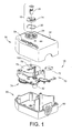
- FIG. 1 is an perspective exploded view of an exemplary embodiment of a valve actuator with locking mechanism
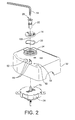
- FIG. 2 is a prospective partial exploded view of a locking button arrangement of the valve actuator of FIG. 1 ;
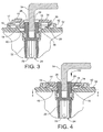
- FIG. 3 is a partial side cross sectional view of the locking button arrangement in an unlocked position
- FIG. 4 is a partial side cross sectional view of the locking button arrangement in a locked position
- FIG. 5 is a top cross sectional view of a locking feature of the locking button arrangement of FIG. 2 inserted into a locking cavity of a locking button recess of a housing of the valve actuator of FIG. 1 ;
- FIG. 6 is a prospective view of the valve actuator with a tool inserted into the locking button arrangement of FIG. 2 .
- the valve actuator includes a two-piece housing 30, a locking button arrangement 12, and a drive train assembly 70.
- the housing 30 carries the drive train assembly 70 therein, and the locking button arrangement 12 is operably coupled to the housing 30 and the drive train assembly 70.
- the locking button arrangement 12 is operable to lock the drive train assembly 70 in a desired position through engagement with the housing 30.
- the drive train assembly 70 includes a motor 72.
- the motor supplies the power required to drive the valve actuator 10 between desired positions.
- the motor 72 is coupled to a plurality of interconnected gears 74 operably coupling the motor 72 to an actuator coupling sleeve 82.
- the actuator coupling sleeve 82 receives a valve stem or other shaft of the valve that the valve actuator 10 operates upon.
- the drive train 70 further includes an actuator return device 76.
- the actuator return device stores rotational energy and returns that rotational energy to the drive train 70 in the event that the power supply supplying power to the motor 72 fails.
- the actuator return device 76 supplies stored mechanical energy to the drive train 70 such that the drive train 70 returns a valve coupled to the valve actuator 10 to a predetermined desired position.
- This predetermined position can be what is known in the art as a normally closed or normally open state, or furthermore any position therebetween.
- valve coupled to the valve actuator 10 When the actuator return device 76 returns the valve coupled to the valve actuator 10 to the normally closed position, a valve coupled to the valve actuator 10 is closed. Similarly, in a normally open configuration, when the actuator return device 76 returns the valve connected to the valve actuator 10 to an open position, a valve coupled to the valve actuator 10 is opened.
- the locking button arrangement 12 allows a user to manually reposition the valve actuator 10 and more particularly the valve coupled to the valve actuator 10 to a position other than the predetermined position in the event of a power failure.
- the locking button arrangement 12 allows a user to reopen a normally closed valve that has been closed by way of the actuator return device 76 in the event of a power failure.
- the locking button arrangement 12 allows a user to close a normally open valve when the actuator return device 76 has opened the valve in the event of a power failure.
- the locking button arrangement 12 provides a manual override to a valve actuator 10 that incorporates an actuator return device 76 as a fail safe device.
- the locking button arrangement 12 is illustrated as including a locking button 14, a sleeve 22, and a biasing element 20.
- the locking button arrangement 12 is axially received in a locking button recess 34.
- the locking button recess 34 is formed into a top 32 of the housing 30. It will be recognized that the term “top” and “bottom” when used with respect to the housing 30 are merely terms used for illustrative purposes based on the orientation in the present figures, but the invention is not so limited.
- the sleeve 22 is operably coupled to the actuator return device 76. More particularly, the sleeve 22 is keyed to receive a lock out shaft 78 extending from the drive train 70 such that the sleeve 22 cannot rotate relative to the lock out shaft 78. Also, the locking button 14 is configured to receive the sleeve 22 such that the locking button 14 cannot rotate relative to the sleeve 22. As such, when the locking button 14 is prevented from rotation so too is the lock out shaft 78, that ultimately prevents any rotation of the drive train 70.
- the sleeve 22 is illustrated as having a generally cylindrical profile.
- the sleeve 22 includes a shaft aperture 24 at a first axial end and a button mating feature 28 at a second axial end.
- Sleeve 22 also includes a tool receiving feature that is illustrated as a tool aperture 26 also at the second end of the sleeve.
- the tool aperture 26 is sized to receive a tool 54 that is keyed to the shape of the tool aperture 26.
- the button mating feature 28 of the sleeve 22 is keyed to the shape of a sleeve mating feature 18 of the locking button 14 so that the sleeve 22 cannot rotate relative to the locking button 14. As such, a rotation of the sleeve 22 by action of the tool 54 therefore results in a rotation of the locking button 14.
- the locking button feature 28 and sleeve mating feature 18 are keyed to one another such that the locking button 14 is slidable in the axial direction relative to the sleeve 22. This functionality allows the locking feature 16 of the locking button 14 to be selectively axially positioned within the locking cavity by sliding the locking button 14 axially relative to the locking sleeve 22.
- the sleeve 22 can be adapted to engage other types of tools. More particularly, in other embodiments the tool aperture 24 can take the form of a phillips head or standard head screw, or other similar geometrical shapes.
- an advantage to using an allen wrench for the tool 54 is the ability to easily provide a sufficient torque to the lock out shaft 78 of the drive train assembly 70.
- the locking button 14 is illustrated in the unlocked position ( FIG. 3 ) and the locked position ( FIG. 4 ).
- the locking button 14 includes a locking feature 16 extending axially away from an underside thereof.
- the locking feature 16 includes an axially extending first locking surface 19 which maintains a frictional contact with a locking cavity 38 of the locking button recess 34 when in the locked position.
- the locking button 14 further includes a guide flange 17.
- the guide flange 17 is operable to maintain the concentric relationship between the locking button 14 and the locking button recess 34. As such, the guide flange 17 extends axially away from an underside of the locking button 14 generally at an outer circumference thereof.
- the locking button 14 further includes a sleeve mating feature 18 in the form of an opening keyed to the button mating feature 28 of the sleeve 22. Also as noted above, the sleeve mating feature 18 receives the sleeve 22 in such a way that the locking button 14 is prevented from rotation relative to the sleeve 22 when the sleeve mating feature 18 engages the button mating feature 28. Although illustrated in FIG. 1 as having a generally round or disc shape, the locking button 14 can take on various other shapes. Additionally, although illustrated as separate components, the sleeve 22 and the locking button 14 can be configured as a one-piece body by, for example, injection molding.
- the locking button recess 34 is illustrated as axially receiving the locking button 14 in both the locked position and the unlocked position.
- the locking button recess 34 includes a locking cavity 38 which is configured and keyed to receive the locking feature 16 of the locking button 14.
- the locking button recess 34 further includes an annular channel 36 sized to receive the biasing element 20 in the form of a wave spring of the locking button arrangement 12.
- the locking cavity 38 includes an axially extending locking surface 40.
- the second locking surface 40 maintains a frictional contact with the first locking surface 19 of the locking feature 16 when the locking button 14 is in the locked position to prevent the locking button from being axially ejected from the locking cavity 38 under the load of the biasing element 20. (See FIG. 4 ).
- the biasing element 20 is shown illustrated disposed within an annular channel 36 and proximate to the guide flange 17 of the locking button 14. As illustrated, the biasing element 20 is a wave spring, however, in other embodiments the biasing element 20 may take the form of other biasing elements such as a compression spring or similar mechanical component.
- the drive train assembly 70 is illustrated as carried within the housing 30. More particularly, the drive train assembly 70 is mounted to a bottom 60 of the housing 30 as well as a top 32 of the housing 30.
- the drive train assembly 70 includes a motor 72 and a plurality of interconnected gears 74 operatively connected to the motor such that each one of the plurality of interconnected gears is required to transmit a torque exerted at an input end of the drive train coupled to the motor 72 to an output end of the drive train defined by an actuator coupling sleeve 82.
- the lock out shaft 78 extends from the center of one of the plurality of interconnected gears 74 along an axis of rotation 105 thereof.
- the actuator coupling sleeve 82 extends from one of the plurality of gears 74 and is operable to couple to the valve stem of a valve such that a rotation of the actuator coupling sleeve 82 results in a rotation of the valve stem.
- the lock out shaft 78 extends from the axis of rotation 105 of one of the plurality of interconnected gears 74 such that rotation of the lock out shaft 78 corresponds to rotation of the gear the lock out shaft 74 extends from.
- the drive train can use other power supply sources, such as for non-limiting example a pneumatic drive.
- the drive train assembly 70 also includes an actuator return device 76 in the form of a power spring 76.
- the power spring 76 is a coil or clock spring coiled about the lock out shaft 78.
- the power spring 76 is wound by the lock out shaft 78 when the motor 72 supplies a torque to the plurality of gears 74.
- the actuator return device 76 is operable to return the valve coupled to the valve actuator 10 to a predetermined position such as a normally closed or normally open position by way of unwinding and thereby supplying a torque to the lock out shaft 78 once power to the motor 72 ceases.
- the valve actuator 10 has an automatic reset function that places the valve in a predetermined setting in the event of a failure of the power supply of the valve actuator 10.
- the locking arrangement 12 allows a user to manually place a valve coupled to the valve actuator 10 in a position other than the a position defined by the predetermined position of the valve actuator 10.
- the locking button 14 is shown in the unlocked position.
- the locking feature 16 of the locking button 14 is axially above the locking cavity 38 of the locking button recess 34. In this way, the locking button 14 is free to rotate a full 360 degrees within the locking button recess 34.
- the locking button 14 cannot rotate relative to the sleeve 22.
- the sleeve 22 fixedly receives the lock out shaft 78.
- any rotation of the locking button 14 will also result in a rotation of the sleeve 22, that in turn will result in a rotation of the lock out shaft 78, that ultimately in turn will result in the rotation of a valve member connected to a actuator coupling sleeve 82 (see FIG. 1 ).
- the lock out shaft 78 rotates. So long as the locking button 14 is in the unlocked position as shown in FIG. 3 , the locking button is free to rotate within the locking button recess 34.
- This functionality allows the valve actuator 10 to freely operate without unwanted jamming or locking when the locking button is not desired to be in the locked position as shown in FIG. 4 . More particularly, and as will be discussed in greater detail below, the locking button 14 maintains an axial spacing from the locking cavity 38 by way of the biasing element 20 when in the unlocked position.
- the locking button 14 as illustrated in the locked position.
- the locking feature 16 of the locking button 14 is disposed within the locking cavity 38 of the locking button recess 34.
- the biasing element 20 is compressed within the channel 36 of the locking button recess 34.
- the locking button 14 When the locking button 14 is in the locked position within the locking button recess 34, the locking button 14 is prevented from rotation relative to the locking button recess 34. As a result, the sleeve 22 is also prevented from rotation about the center axis of the locking button recess 34 because the sleeve 22 cannot rotate relative to the locking button 14. Also as discussed above, the lock out shaft 78 cannot rotate relative to the sleeve 22. Accordingly, when the locking button 14 is in a locked position the entire drive train assembly 70, including the actuator coupling sleeve 82 is prevented from rotation.
- FIG. 5 the locking feature 16 of the locking button 14 is shown in the locked position within the locking cavity 38 of the locking button recess 34.
- the locking feature 16 is generally five-sided figure possessing generally the same dimensions as the locking cavity 38 such that the locking feature 16 and locking cavity 38 maintain a keyed complimentary mating relationship. As a result, when the locking feature 16 is in the locking cavity 38 it cannot rotate thereabout.
- the frictional contact between the first and second locking surfaces 19, 40 caused by the torque provided by the actuator return device 76 is strong enough to resist the axial biasing exerted upon the locking button 14 by the biasing element 20 thereunder. Because the locking button 14 maintains a locked position with the locking button recess 34 via frictional contact between the first and second locking surfaces 19, 40, the locking button 14 will return to the unlocked position once this frictional contact is removed. Accordingly, once the power is resupplied to the valve actuator 10 and more particularly to the motor 72, the drive train will rotate the lock out shaft 78 in a direction opposite to the direction of rotation supplied by the actuator return device 76, which will ultimately result in the frictional contact between the first and second locking surfaces 19 and 40 to cease.
- the locking cavity 38 receives the locking feature 16 by pure axial translation of the locking button 14.
- the overall stress exerted upon the locking button 14 when in the locked position is reduced because the locking button 14 is not subjected to any distortion or bending moments unlike other locking mechanisms, but is generally under torsional stress due to the engagement of the first and second lock out surfaces 19, 40.
- the biasing element 20 will freely bias the locking button 14 axially away from the locking button recess 34 in such a way that the locking feature 16 is ejected from and disposed axially above the locking cavity 38. Therefore, by simply resupplying energy to the valve actuator 10 from a power supply the valve actuator 10 will resume normal operation and not experience any locking or jamming due to the locking button 14 and locking cavity 38 relationship as discussed above.
- the locking button recess 34 is formed into the top 32 of the housing 30.
- the locking button 14 is configured to lock directly to the housing 30 of the valve actuator 10 via the locking recess 34 formed into the top cover 32.
- the housing and locking button are manufactured from a formed plastic such that the features of the locking button recess 34 and the locking button 14 are formed simultaneously during injection molding, for example.
- the top 32 of the housing 30 includes a first reference mark 44 and the locking button 14 includes a second reference mark 44 to indicate by their radial alignment when the locking button 14 is in the appropriate position such that the locking feature 16 will slidably and axially engage the locking cavity 38.
- the drive train assembly 70 is configured such that a certain number of rotations of the sleeve 22 results in a certain amount of opening or closing of a valve coupled to the actuator coupling sleeve 82 of the valve actuator 10. For example, in one embodiment, eight rotations of the sleeve will result in a 90° rotation of the actuator coupling sleeve 82, and in turn the valve stem coupled thereto. This information allows the user to determine how many turns of the locking button arrangement 12 are required to open or close the valve coupled to the valve actuator 10 a desired amount before placing the valve actuator 10 in the locked position.
- the top 32 of the housing 30 includes a plurality of tool retaining clips 48 and tool risers 52.
- the tool retaining clips 48 fixedly attach the tool 54 to the housing 30.
- the tool risers 52 minimize the overall surface contact between the tool 54 and the housing 30 so that a user can easily remove the tool 54 from the tool retaining clips 48.
- valve actuator 10 Having discussed the structural attributes of the valve actuator 10 as described above, a description of the operation of the valve actuator 10 is provided herein below.
- a user inserts an end of the tool 54 into the tool aperture 26 of the sleeve 22.
- the user then rotates the sleeve so as to provide a torque in a direction 100 that opposes the torque supplied by the acutator return device 76 until the locking feature 16 is in axial alignment with the locking cavity 38.
- the user can depress the locking button 14 relative to the sleeve 22 into the locking cavity 38 by simply pressing the locking button 14 in an axial direction 102 towards the housing 30 and thereby engage the same.
- the tool 54 can be removed from the sleeve 22 by maintaining downward pressure upon the locking button 14 and pulling upward upon the tool 54. The user can then relieve the downward pressure from the locking button 14 as the locking button will maintain its locked position under the frictional contact between the first and second locking surfaces 19, 40 (see FIG. 3 ).
- the end of the tool can then be placed in the tool cavity 50 and clipped to the tool retaining clip 48.
- the user simply resupplies power to the motor 72 which in turn will drive the drive train assembly 70 to include the lock out shaft 78 in a direction opposite the direction supplied by the actuator return device 76. (See FIG. 1 ).
- valve actuator 10 provides all of the benefits of a valve actuator 10 with a predetermined default position in the event of a power failure, while also providing a valve actuator that can manually override the default positioning functionality.
- the valve actuator 10 accomplishes this functionality by a locking button arrangement 12 that is selectively engageable with a housing 30 of the valve actuator 10. When in the locked, i.e. engaged position, the locking button arrangement 12 maintains a frictional contact with the locking button recess 34 via the first and second locking surfaces 19, 40.
Landscapes
- Engineering & Computer Science (AREA)
- General Engineering & Computer Science (AREA)
- Mechanical Engineering (AREA)
- Preventing Unauthorised Actuation Of Valves (AREA)
- Fluid-Driven Valves (AREA)
- Mechanically-Actuated Valves (AREA)
Applications Claiming Priority (1)
| Application Number | Priority Date | Filing Date | Title |
|---|---|---|---|
| US12/636,495 US8157242B2 (en) | 2009-12-11 | 2009-12-11 | Valve actuator with lock mechanism |
Publications (3)
| Publication Number | Publication Date |
|---|---|
| EP2360404A2 true EP2360404A2 (de) | 2011-08-24 |
| EP2360404A3 EP2360404A3 (de) | 2011-11-30 |
| EP2360404B1 EP2360404B1 (de) | 2013-05-01 |
Family
ID=43581539
Family Applications (1)
| Application Number | Title | Priority Date | Filing Date |
|---|---|---|---|
| EP10015414.5A Active EP2360404B1 (de) | 2009-12-11 | 2010-12-08 | Ventilaktuator mit Verriegelungsmechanismus |
Country Status (4)
| Country | Link |
|---|---|
| US (1) | US8157242B2 (de) |
| EP (1) | EP2360404B1 (de) |
| CN (1) | CN102095018B (de) |
| ES (1) | ES2423316T3 (de) |
Families Citing this family (9)
| Publication number | Priority date | Publication date | Assignee | Title |
|---|---|---|---|---|
| US8695453B2 (en) * | 2011-03-08 | 2014-04-15 | Fisher Controls International Llc | Lockout devices for use with rotary actuators |
| CN105074304A (zh) * | 2013-04-03 | 2015-11-18 | 锡克拜控股有限公司 | 一次性使用的阀 |
| CN104637178A (zh) * | 2014-12-16 | 2015-05-20 | 宇星科技发展(深圳)有限公司 | 一种刷卡排污总量控制系统及控制方法 |
| DE102015106673A1 (de) * | 2015-04-29 | 2016-11-03 | Dr. Ing. H.C. F. Porsche Aktiengesellschaft | Fluiddrehregler |
| EP3150888A1 (de) * | 2015-10-01 | 2017-04-05 | IMI Hydronic Engineering International SA | Aktuator zur steuerung eines ventil |
| US10920814B2 (en) * | 2018-04-05 | 2021-02-16 | Honeywell International Inc. | Bracket for mounting an actuator to an actuatable component |
| EP3569895B1 (de) | 2018-05-14 | 2020-06-24 | Siemens Schweiz AG | Stellantrieb sowie verfahren zum einstellen eines stellantriebs |
| WO2021228780A1 (en) | 2020-05-11 | 2021-11-18 | Rotiny Aps | Actuator for fluid flow controllers |
| US12473989B2 (en) * | 2023-08-15 | 2025-11-18 | Nibco Inc. | Serviceable swing check valve with integrated strainer and removable drain |
Family Cites Families (66)
| Publication number | Priority date | Publication date | Assignee | Title |
|---|---|---|---|---|
| US1590074A (en) * | 1925-10-28 | 1926-06-22 | Booker William Edw | Gas cock |
| US2205512A (en) * | 1938-04-18 | 1940-06-25 | Jr Claude D Anderson | Valve control |
| US2227914A (en) * | 1938-08-15 | 1941-01-07 | Saunders Philip Keith | Diaphragm valve |
| US2591951A (en) * | 1946-01-11 | 1952-04-08 | Ideal Mfg Company | Reciprocating pump |
| US2646074A (en) * | 1948-07-28 | 1953-07-21 | R S Products Corp | Variable stroke cushioned valve |
| US2761424A (en) * | 1948-07-28 | 1956-09-04 | R S Products Corp | Variable stroke cushioned valves |
| US2855828A (en) * | 1950-03-31 | 1958-10-14 | Philias H Girouard | Rapid fire gun turret apparatus |
| US3319646A (en) * | 1964-12-24 | 1967-05-16 | Honeywell Inc | Control apparatus |
| US3707992A (en) | 1970-11-09 | 1973-01-02 | Skinner Precision Ind Inc | Electromagnetic valve assembly |
| US4090589A (en) * | 1975-10-23 | 1978-05-23 | John Herman Fitzwater | Fail safe valve actuator |
| ES228973Y (es) * | 1976-06-01 | 1978-03-16 | Grifo de gas. | |
| US4078763A (en) * | 1976-08-04 | 1978-03-14 | Naoyuki Yamamoto | Oil extractor for vehicle engines and the like |
| US4130030A (en) * | 1977-04-04 | 1978-12-19 | Dresser Industries, Inc. | Manually shifted actuator |
| US4274445A (en) * | 1979-04-10 | 1981-06-23 | Pall Corporation | Pressure balanced three-way transfer valve |
| DE3125347C2 (de) | 1981-06-27 | 1983-04-07 | Rheinische Armaturen- und Maschinenfabrik Albert Sempell, 4052 Korschenbroich | "Einstellbare Armaturenverriegelung" |
| US4460154A (en) * | 1981-11-25 | 1984-07-17 | Fmc Corporation | Manually operable override for use with a linear actuator |
| US4533114A (en) * | 1983-02-08 | 1985-08-06 | Posi-Seal International, Inc. | Fail-safe actuator for rotary valves |
| JPS6093098U (ja) * | 1983-12-01 | 1985-06-25 | 日本酸素株式会社 | 容器弁の遠隔開閉器具 |
| US4549446A (en) * | 1984-02-06 | 1985-10-29 | Johnson Service Company | Motorized valve actuator |
| US4702123A (en) * | 1984-05-09 | 1987-10-27 | Aisin Seiki Kabushikikaisha | Apparatus for driving rod for rotation |
| US4647007A (en) * | 1986-02-24 | 1987-03-03 | Peter Bajka | Valve actuator with manual disengagement assembly |
| US4705063A (en) * | 1986-10-30 | 1987-11-10 | The Fulflo Specialties Co., Inc. | Motor operated valve assembly |
| US4759386A (en) * | 1987-01-20 | 1988-07-26 | Pennwalt Corporation | Electromechanical linear actuator |
| IT1217337B (it) * | 1988-02-03 | 1990-03-22 | Pettinaroli Spa | Valvola a sfera con dispositivo di bloccaggio della maniglia |
| US5062611A (en) * | 1990-07-31 | 1991-11-05 | Eaton Corporation | Servo operated valve assembly |
| US5205534A (en) * | 1991-02-25 | 1993-04-27 | Taco, Inc. | Actuator and zone valve |
| US5215112A (en) * | 1992-03-11 | 1993-06-01 | Dyna-Torque Company, Inc. | Valve actuator locking bracket |
| US5188335A (en) * | 1992-06-02 | 1993-02-23 | Fratelli Pettinaroli S.P.A. | Ball valve with lockable security device |
| US5310021A (en) * | 1993-02-18 | 1994-05-10 | Barber-Colman Company | Motor-driven, spring-returned rotary actuator |
| US5758684A (en) * | 1995-02-15 | 1998-06-02 | Johnson Service Company | Return-to-normal modular actuator |
| CH691246A5 (de) * | 1995-04-11 | 2001-05-31 | Siemens Building Tech Ag | Antriebsvorrichtung für ein Stellglied. |
| US5507469A (en) * | 1995-05-02 | 1996-04-16 | Soderberg Research & Development, Inc. | Valve actuator system for initial torque reduction |
| US5513831A (en) * | 1995-05-17 | 1996-05-07 | Seward; Alfred L. | Safety control knob for hot water valve |
| US6003837A (en) * | 1996-02-20 | 1999-12-21 | Bray International, Inc. | Valve actuator |
| US6446666B1 (en) * | 1997-03-22 | 2002-09-10 | Eja Limited | Valve lock and adapter |
| US5832779A (en) * | 1997-04-03 | 1998-11-10 | Dresser Industries, Inc. | Actuator assembly with manual locking device |
| US6073907A (en) | 1997-11-07 | 2000-06-13 | Erie Manufacturing Company | Removable and interchangeable valve actuator system |
| EP1121550A2 (de) * | 1998-10-13 | 2001-08-08 | Swagelok Company | Verriegelbarer drehhandgriff |
| US6260819B1 (en) * | 1999-10-19 | 2001-07-17 | Southern Spears Manufacturing Co. | Locking valve |
| US6575427B1 (en) * | 1999-11-10 | 2003-06-10 | Visteon Global Technologies, Inc. | Electronic throttle control mechanism with reduced friction and wear |
| US6276664B1 (en) | 1999-11-19 | 2001-08-21 | Eaton Corporation | Worm driving a servo actuator with spring return and rotary valve employing same |
| US6347782B1 (en) * | 2000-01-31 | 2002-02-19 | Ajit Singh Gill | Axial actuator |
| US6929238B2 (en) * | 2000-02-18 | 2005-08-16 | Ga Industries Inc. | Electric motor actuated stop and self-closing check valve |
| US6408901B2 (en) * | 2000-03-13 | 2002-06-25 | Stoneridge Control Devices, Inc. | Actuator with anti-pinch feature and integrated position control |
| NO312376B1 (no) * | 2000-05-16 | 2002-04-29 | Kongsberg Offshore As | Fremgangsmåte og anordning for styring av ventiler av en undervannsinstallasjon |
| PL195691B1 (pl) * | 2000-06-21 | 2007-10-31 | Zaklad Urzadzen Gazowniczych G | Kurek kulowy i klucz do kurka kulowego |
| US6619388B2 (en) * | 2001-02-15 | 2003-09-16 | Halliburton Energy Services, Inc. | Fail safe surface controlled subsurface safety valve for use in a well |
| US6974119B2 (en) * | 2001-09-27 | 2005-12-13 | Robert Bosch Gmbh | Actuator |
| US6725976B2 (en) * | 2002-03-20 | 2004-04-27 | Invensys Building Systems Inc. | Manual override and locking mechanism and actuator including same |
| US7066301B2 (en) | 2002-03-20 | 2006-06-27 | Invensys Building Systems, Inc. | Linear actuator having manual override and locking mechanism |
| JP2003287155A (ja) * | 2002-03-29 | 2003-10-10 | Sumitomo Heavy Ind Ltd | バルブ駆動装置のシリーズ |
| JP4055547B2 (ja) * | 2002-10-25 | 2008-03-05 | 株式会社デンソー | 電子制御式スロットル制御装置 |
| US7048251B2 (en) * | 2002-11-08 | 2006-05-23 | Caleffi S.P.A. | Valve with removable actuator |
| US6953084B2 (en) * | 2003-01-10 | 2005-10-11 | Woodward Governor Company | Actuator for well-head valve or other similar applications and system incorporating same |
| ITBO20030033A1 (it) * | 2003-01-24 | 2004-07-25 | Magneti Marelli Powertrain Spa | Valvola a farfalla servoassistita per un motore a |
| US6979965B2 (en) * | 2003-04-24 | 2005-12-27 | Honeywell International Inc. | Spring return actuator for a damper |
| ITBS20030041A1 (it) * | 2003-04-30 | 2004-11-01 | Valvosanitaria Bugatti S P A | Valvola o rubinetto per fluidi con dispositivo di fermo meccanico. |
| GB2404717B (en) * | 2003-07-17 | 2005-12-21 | Rotork Controls | Drive mechanisms for valve actuators |
| ITBO20030530A1 (it) * | 2003-09-15 | 2005-03-16 | Magneti Marelli Powertrain Spa | Valvola a farfalla servoassistita provvista di una molla a flessione e di una molla a spirale per stabilire la posizione di limp-home |
| JP2005140034A (ja) | 2003-11-07 | 2005-06-02 | Keihin Corp | 電子制御弁の原点復帰装置 |
| US7017884B2 (en) * | 2004-01-08 | 2006-03-28 | Woodward Governor Company | Fluid metering valve |
| US7509972B2 (en) * | 2005-07-07 | 2009-03-31 | Parker-Hannifin Corporation | Pneumatic valve with lockout |
| US7104518B1 (en) * | 2005-10-21 | 2006-09-12 | George William Wood | Automatic valve manual lock out |
| CN2846913Y (zh) * | 2005-12-08 | 2006-12-13 | 浙江中宝自控元件有限公司 | 一种电子膨胀阀 |
| US7913972B2 (en) * | 2008-02-04 | 2011-03-29 | Schneider Electric Buildings, Llc | Two position actuator with mechanical hold |
| US8215614B2 (en) * | 2008-02-04 | 2012-07-10 | Schneider Electric Buildings, Llc | Two position actuator impact limiter |
-
2009
- 2009-12-11 US US12/636,495 patent/US8157242B2/en active Active
-
2010
- 2010-12-08 EP EP10015414.5A patent/EP2360404B1/de active Active
- 2010-12-08 ES ES10015414T patent/ES2423316T3/es active Active
- 2010-12-09 CN CN2010105867715A patent/CN102095018B/zh active Active
Non-Patent Citations (1)
| Title |
|---|
| None |
Also Published As
| Publication number | Publication date |
|---|---|
| CN102095018A (zh) | 2011-06-15 |
| ES2423316T3 (es) | 2013-09-19 |
| EP2360404B1 (de) | 2013-05-01 |
| US20110140015A1 (en) | 2011-06-16 |
| CN102095018B (zh) | 2013-03-20 |
| US8157242B2 (en) | 2012-04-17 |
| EP2360404A3 (de) | 2011-11-30 |
Similar Documents
| Publication | Publication Date | Title |
|---|---|---|
| US8157242B2 (en) | Valve actuator with lock mechanism | |
| US9145113B2 (en) | Transmission parking pawl actuation assembly | |
| JP4781010B2 (ja) | 電動弁 | |
| US7607637B2 (en) | Reduction gearing for an electric actuator | |
| US5490660A (en) | Manual device for valve | |
| AU2009221395B2 (en) | An adjustable roller blind tube | |
| KR102379149B1 (ko) | 2개 이상의 차동유성감속기를 구비한 컴팩트 스프링 리턴 액추에이터 | |
| US11703893B2 (en) | Gas pressure reducer with cam commanded shut-off valve | |
| EP1515023B1 (de) | Elektronisch gesteuerte Drosselklappe mit einer Blattfeder und einer Spiralfeder zum Einstellen der Notfahrposition | |
| US7913972B2 (en) | Two position actuator with mechanical hold | |
| CN109282027A (zh) | 一种p档执行装置及方法 | |
| US20250334152A1 (en) | Torque-limiting spindle | |
| EP3359853B1 (de) | Indikator für den öffnungs- und/oder schliessstatus eines wasserhahns oder druckminderers | |
| CN108468800A (zh) | 具有释放和返回机构的致动器 | |
| JP4509391B2 (ja) | リーフスプリング弁 | |
| JPWO2000058649A1 (ja) | リーフスプリング弁 | |
| EP3256923B1 (de) | Ventilanordnung mit einstellbarem federsitz | |
| JP2008256031A (ja) | バルブ用アクチュエータ | |
| JP4358611B2 (ja) | 緊急遮断弁 | |
| EP1820605A2 (de) | Air-Driver-Vorrichtung | |
| CN108233606B (zh) | 驱动器的手动超控装置 | |
| CN224188139U (zh) | 一种手动传动机构及电动执行器 | |
| US7210669B1 (en) | Deformable fastener | |
| US12467389B2 (en) | Valve bridge with integrated spline bushing for lost motion | |
| JPH1182795A (ja) | スプリングリターン式アクチュエータ |
Legal Events
| Date | Code | Title | Description |
|---|---|---|---|
| PUAI | Public reference made under article 153(3) epc to a published international application that has entered the european phase |
Free format text: ORIGINAL CODE: 0009012 |
|
| AK | Designated contracting states |
Kind code of ref document: A2 Designated state(s): AL AT BE BG CH CY CZ DE DK EE ES FI FR GB GR HR HU IE IS IT LI LT LU LV MC MK MT NL NO PL PT RO RS SE SI SK SM TR |
|
| AX | Request for extension of the european patent |
Extension state: BA ME |
|
| PUAL | Search report despatched |
Free format text: ORIGINAL CODE: 0009013 |
|
| AK | Designated contracting states |
Kind code of ref document: A3 Designated state(s): AL AT BE BG CH CY CZ DE DK EE ES FI FR GB GR HR HU IE IS IT LI LT LU LV MC MK MT NL NO PL PT RO RS SE SI SK SM TR |
|
| AX | Request for extension of the european patent |
Extension state: BA ME |
|
| RIC1 | Information provided on ipc code assigned before grant |
Ipc: F16K 35/02 20060101AFI20111021BHEP |
|
| 17P | Request for examination filed |
Effective date: 20120529 |
|
| GRAP | Despatch of communication of intention to grant a patent |
Free format text: ORIGINAL CODE: EPIDOSNIGR1 |
|
| GRAS | Grant fee paid |
Free format text: ORIGINAL CODE: EPIDOSNIGR3 |
|
| GRAA | (expected) grant |
Free format text: ORIGINAL CODE: 0009210 |
|
| AK | Designated contracting states |
Kind code of ref document: B1 Designated state(s): AL AT BE BG CH CY CZ DE DK EE ES FI FR GB GR HR HU IE IS IT LI LT LU LV MC MK MT NL NO PL PT RO RS SE SI SK SM TR |
|
| REG | Reference to a national code |
Ref country code: GB Ref legal event code: FG4D |
|
| REG | Reference to a national code |
Ref country code: CH Ref legal event code: EP Ref country code: AT Ref legal event code: REF Ref document number: 610166 Country of ref document: AT Kind code of ref document: T Effective date: 20130515 |
|
| REG | Reference to a national code |
Ref country code: IE Ref legal event code: FG4D |
|
| REG | Reference to a national code |
Ref country code: DE Ref legal event code: R096 Ref document number: 602010006597 Country of ref document: DE Effective date: 20130704 |
|
| REG | Reference to a national code |
Ref country code: AT Ref legal event code: MK05 Ref document number: 610166 Country of ref document: AT Kind code of ref document: T Effective date: 20130501 |
|
| REG | Reference to a national code |
Ref country code: ES Ref legal event code: FG2A Ref document number: 2423316 Country of ref document: ES Kind code of ref document: T3 Effective date: 20130919 |
|
| REG | Reference to a national code |
Ref country code: NL Ref legal event code: VDEP Effective date: 20130501 |
|
| REG | Reference to a national code |
Ref country code: LT Ref legal event code: MG4D |
|
| PG25 | Lapsed in a contracting state [announced via postgrant information from national office to epo] |
Ref country code: FI Free format text: LAPSE BECAUSE OF FAILURE TO SUBMIT A TRANSLATION OF THE DESCRIPTION OR TO PAY THE FEE WITHIN THE PRESCRIBED TIME-LIMIT Effective date: 20130501 Ref country code: SE Free format text: LAPSE BECAUSE OF FAILURE TO SUBMIT A TRANSLATION OF THE DESCRIPTION OR TO PAY THE FEE WITHIN THE PRESCRIBED TIME-LIMIT Effective date: 20130501 Ref country code: AT Free format text: LAPSE BECAUSE OF FAILURE TO SUBMIT A TRANSLATION OF THE DESCRIPTION OR TO PAY THE FEE WITHIN THE PRESCRIBED TIME-LIMIT Effective date: 20130501 Ref country code: NO Free format text: LAPSE BECAUSE OF FAILURE TO SUBMIT A TRANSLATION OF THE DESCRIPTION OR TO PAY THE FEE WITHIN THE PRESCRIBED TIME-LIMIT Effective date: 20130801 Ref country code: PT Free format text: LAPSE BECAUSE OF FAILURE TO SUBMIT A TRANSLATION OF THE DESCRIPTION OR TO PAY THE FEE WITHIN THE PRESCRIBED TIME-LIMIT Effective date: 20130902 Ref country code: SI Free format text: LAPSE BECAUSE OF FAILURE TO SUBMIT A TRANSLATION OF THE DESCRIPTION OR TO PAY THE FEE WITHIN THE PRESCRIBED TIME-LIMIT Effective date: 20130501 Ref country code: IS Free format text: LAPSE BECAUSE OF FAILURE TO SUBMIT A TRANSLATION OF THE DESCRIPTION OR TO PAY THE FEE WITHIN THE PRESCRIBED TIME-LIMIT Effective date: 20130901 Ref country code: GR Free format text: LAPSE BECAUSE OF FAILURE TO SUBMIT A TRANSLATION OF THE DESCRIPTION OR TO PAY THE FEE WITHIN THE PRESCRIBED TIME-LIMIT Effective date: 20130802 Ref country code: LT Free format text: LAPSE BECAUSE OF FAILURE TO SUBMIT A TRANSLATION OF THE DESCRIPTION OR TO PAY THE FEE WITHIN THE PRESCRIBED TIME-LIMIT Effective date: 20130501 |
|
| PG25 | Lapsed in a contracting state [announced via postgrant information from national office to epo] |
Ref country code: RS Free format text: LAPSE BECAUSE OF FAILURE TO SUBMIT A TRANSLATION OF THE DESCRIPTION OR TO PAY THE FEE WITHIN THE PRESCRIBED TIME-LIMIT Effective date: 20130501 Ref country code: PL Free format text: LAPSE BECAUSE OF FAILURE TO SUBMIT A TRANSLATION OF THE DESCRIPTION OR TO PAY THE FEE WITHIN THE PRESCRIBED TIME-LIMIT Effective date: 20130501 Ref country code: HR Free format text: LAPSE BECAUSE OF FAILURE TO SUBMIT A TRANSLATION OF THE DESCRIPTION OR TO PAY THE FEE WITHIN THE PRESCRIBED TIME-LIMIT Effective date: 20130501 Ref country code: CY Free format text: LAPSE BECAUSE OF FAILURE TO SUBMIT A TRANSLATION OF THE DESCRIPTION OR TO PAY THE FEE WITHIN THE PRESCRIBED TIME-LIMIT Effective date: 20130501 Ref country code: BG Free format text: LAPSE BECAUSE OF FAILURE TO SUBMIT A TRANSLATION OF THE DESCRIPTION OR TO PAY THE FEE WITHIN THE PRESCRIBED TIME-LIMIT Effective date: 20130801 |
|
| PG25 | Lapsed in a contracting state [announced via postgrant information from national office to epo] |
Ref country code: LV Free format text: LAPSE BECAUSE OF FAILURE TO SUBMIT A TRANSLATION OF THE DESCRIPTION OR TO PAY THE FEE WITHIN THE PRESCRIBED TIME-LIMIT Effective date: 20130501 |
|
| PG25 | Lapsed in a contracting state [announced via postgrant information from national office to epo] |
Ref country code: SK Free format text: LAPSE BECAUSE OF FAILURE TO SUBMIT A TRANSLATION OF THE DESCRIPTION OR TO PAY THE FEE WITHIN THE PRESCRIBED TIME-LIMIT Effective date: 20130501 Ref country code: CZ Free format text: LAPSE BECAUSE OF FAILURE TO SUBMIT A TRANSLATION OF THE DESCRIPTION OR TO PAY THE FEE WITHIN THE PRESCRIBED TIME-LIMIT Effective date: 20130501 Ref country code: EE Free format text: LAPSE BECAUSE OF FAILURE TO SUBMIT A TRANSLATION OF THE DESCRIPTION OR TO PAY THE FEE WITHIN THE PRESCRIBED TIME-LIMIT Effective date: 20130501 Ref country code: BE Free format text: LAPSE BECAUSE OF FAILURE TO SUBMIT A TRANSLATION OF THE DESCRIPTION OR TO PAY THE FEE WITHIN THE PRESCRIBED TIME-LIMIT Effective date: 20130501 Ref country code: DK Free format text: LAPSE BECAUSE OF FAILURE TO SUBMIT A TRANSLATION OF THE DESCRIPTION OR TO PAY THE FEE WITHIN THE PRESCRIBED TIME-LIMIT Effective date: 20130501 |
|
| PG25 | Lapsed in a contracting state [announced via postgrant information from national office to epo] |
Ref country code: RO Free format text: LAPSE BECAUSE OF FAILURE TO SUBMIT A TRANSLATION OF THE DESCRIPTION OR TO PAY THE FEE WITHIN THE PRESCRIBED TIME-LIMIT Effective date: 20130501 Ref country code: NL Free format text: LAPSE BECAUSE OF FAILURE TO SUBMIT A TRANSLATION OF THE DESCRIPTION OR TO PAY THE FEE WITHIN THE PRESCRIBED TIME-LIMIT Effective date: 20130501 Ref country code: IT Free format text: LAPSE BECAUSE OF FAILURE TO SUBMIT A TRANSLATION OF THE DESCRIPTION OR TO PAY THE FEE WITHIN THE PRESCRIBED TIME-LIMIT Effective date: 20130501 |
|
| PLBE | No opposition filed within time limit |
Free format text: ORIGINAL CODE: 0009261 |
|
| STAA | Information on the status of an ep patent application or granted ep patent |
Free format text: STATUS: NO OPPOSITION FILED WITHIN TIME LIMIT |
|
| 26N | No opposition filed |
Effective date: 20140204 |
|
| REG | Reference to a national code |
Ref country code: DE Ref legal event code: R097 Ref document number: 602010006597 Country of ref document: DE Effective date: 20140204 |
|
| PG25 | Lapsed in a contracting state [announced via postgrant information from national office to epo] |
Ref country code: LU Free format text: LAPSE BECAUSE OF FAILURE TO SUBMIT A TRANSLATION OF THE DESCRIPTION OR TO PAY THE FEE WITHIN THE PRESCRIBED TIME-LIMIT Effective date: 20131208 |
|
| REG | Reference to a national code |
Ref country code: IE Ref legal event code: MM4A |
|
| PG25 | Lapsed in a contracting state [announced via postgrant information from national office to epo] |
Ref country code: IE Free format text: LAPSE BECAUSE OF NON-PAYMENT OF DUE FEES Effective date: 20131208 |
|
| PG25 | Lapsed in a contracting state [announced via postgrant information from national office to epo] |
Ref country code: MC Free format text: LAPSE BECAUSE OF FAILURE TO SUBMIT A TRANSLATION OF THE DESCRIPTION OR TO PAY THE FEE WITHIN THE PRESCRIBED TIME-LIMIT Effective date: 20130501 |
|
| PG25 | Lapsed in a contracting state [announced via postgrant information from national office to epo] |
Ref country code: SM Free format text: LAPSE BECAUSE OF FAILURE TO SUBMIT A TRANSLATION OF THE DESCRIPTION OR TO PAY THE FEE WITHIN THE PRESCRIBED TIME-LIMIT Effective date: 20130501 |
|
| PG25 | Lapsed in a contracting state [announced via postgrant information from national office to epo] |
Ref country code: TR Free format text: LAPSE BECAUSE OF FAILURE TO SUBMIT A TRANSLATION OF THE DESCRIPTION OR TO PAY THE FEE WITHIN THE PRESCRIBED TIME-LIMIT Effective date: 20130501 |
|
| PG25 | Lapsed in a contracting state [announced via postgrant information from national office to epo] |
Ref country code: HU Free format text: LAPSE BECAUSE OF FAILURE TO SUBMIT A TRANSLATION OF THE DESCRIPTION OR TO PAY THE FEE WITHIN THE PRESCRIBED TIME-LIMIT; INVALID AB INITIO Effective date: 20101208 Ref country code: MK Free format text: LAPSE BECAUSE OF FAILURE TO SUBMIT A TRANSLATION OF THE DESCRIPTION OR TO PAY THE FEE WITHIN THE PRESCRIBED TIME-LIMIT Effective date: 20130501 |
|
| REG | Reference to a national code |
Ref country code: CH Ref legal event code: PL |
|
| PG25 | Lapsed in a contracting state [announced via postgrant information from national office to epo] |
Ref country code: MT Free format text: LAPSE BECAUSE OF FAILURE TO SUBMIT A TRANSLATION OF THE DESCRIPTION OR TO PAY THE FEE WITHIN THE PRESCRIBED TIME-LIMIT Effective date: 20130501 |
|
| PG25 | Lapsed in a contracting state [announced via postgrant information from national office to epo] |
Ref country code: LI Free format text: LAPSE BECAUSE OF NON-PAYMENT OF DUE FEES Effective date: 20141231 Ref country code: CH Free format text: LAPSE BECAUSE OF NON-PAYMENT OF DUE FEES Effective date: 20141231 |
|
| REG | Reference to a national code |
Ref country code: FR Ref legal event code: PLFP Year of fee payment: 6 |
|
| REG | Reference to a national code |
Ref country code: FR Ref legal event code: PLFP Year of fee payment: 7 |
|
| REG | Reference to a national code |
Ref country code: FR Ref legal event code: PLFP Year of fee payment: 8 |
|
| PG25 | Lapsed in a contracting state [announced via postgrant information from national office to epo] |
Ref country code: AL Free format text: LAPSE BECAUSE OF FAILURE TO SUBMIT A TRANSLATION OF THE DESCRIPTION OR TO PAY THE FEE WITHIN THE PRESCRIBED TIME-LIMIT Effective date: 20130501 |
|
| REG | Reference to a national code |
Ref country code: DE Ref legal event code: R082 Ref document number: 602010006597 Country of ref document: DE Representative=s name: MURGITROYD GERMANY PATENTANWALTSGESELLSCHAFT M, DE Ref country code: DE Ref legal event code: R081 Ref document number: 602010006597 Country of ref document: DE Owner name: SCHNEIDER ELECTRIC BUILDINGS AMERICAS, INC., C, US Free format text: FORMER OWNER: SCHNEIDER ELECTRIC BUILDINGS, LLC, LOVES PARK, ILL., US Ref country code: DE Ref legal event code: R082 Ref document number: 602010006597 Country of ref document: DE Representative=s name: MURGITROYD & COMPANY, DE |
|
| REG | Reference to a national code |
Ref country code: GB Ref legal event code: 732E Free format text: REGISTERED BETWEEN 20231012 AND 20231018 |
|
| REG | Reference to a national code |
Ref country code: ES Ref legal event code: PC2A Owner name: SCHNEIDER ELECTRIC BUILDINGS AMERICAS, INC. Effective date: 20240917 |
|
| PGFP | Annual fee paid to national office [announced via postgrant information from national office to epo] |
Ref country code: GB Payment date: 20241217 Year of fee payment: 15 |
|
| PGFP | Annual fee paid to national office [announced via postgrant information from national office to epo] |
Ref country code: FR Payment date: 20241227 Year of fee payment: 15 |
|
| PGFP | Annual fee paid to national office [announced via postgrant information from national office to epo] |
Ref country code: DE Payment date: 20241227 Year of fee payment: 15 |
|
| PGFP | Annual fee paid to national office [announced via postgrant information from national office to epo] |
Ref country code: ES Payment date: 20250114 Year of fee payment: 15 |