EP2360438B1 - Fluidturbulator für Erdsonde - Google Patents
Fluidturbulator für Erdsonde Download PDFInfo
- Publication number
- EP2360438B1 EP2360438B1 EP11154105.8A EP11154105A EP2360438B1 EP 2360438 B1 EP2360438 B1 EP 2360438B1 EP 11154105 A EP11154105 A EP 11154105A EP 2360438 B1 EP2360438 B1 EP 2360438B1
- Authority
- EP
- European Patent Office
- Prior art keywords
- heat exchanger
- borehole heat
- disc
- annular
- fluid
- Prior art date
- Legal status (The legal status is an assumption and is not a legal conclusion. Google has not performed a legal analysis and makes no representation as to the accuracy of the status listed.)
- Active
Links
Images


Classifications
-
- F—MECHANICAL ENGINEERING; LIGHTING; HEATING; WEAPONS; BLASTING
- F24—HEATING; RANGES; VENTILATING
- F24T—GEOTHERMAL COLLECTORS; GEOTHERMAL SYSTEMS
- F24T10/00—Geothermal collectors
- F24T10/10—Geothermal collectors with circulation of working fluids through underground channels, the working fluids not coming into direct contact with the ground
- F24T10/13—Geothermal collectors with circulation of working fluids through underground channels, the working fluids not coming into direct contact with the ground using tube assemblies suitable for insertion into boreholes in the ground, e.g. geothermal probes
-
- Y—GENERAL TAGGING OF NEW TECHNOLOGICAL DEVELOPMENTS; GENERAL TAGGING OF CROSS-SECTIONAL TECHNOLOGIES SPANNING OVER SEVERAL SECTIONS OF THE IPC; TECHNICAL SUBJECTS COVERED BY FORMER USPC CROSS-REFERENCE ART COLLECTIONS [XRACs] AND DIGESTS
- Y02—TECHNOLOGIES OR APPLICATIONS FOR MITIGATION OR ADAPTATION AGAINST CLIMATE CHANGE
- Y02E—REDUCTION OF GREENHOUSE GAS [GHG] EMISSIONS, RELATED TO ENERGY GENERATION, TRANSMISSION OR DISTRIBUTION
- Y02E10/00—Energy generation through renewable energy sources
- Y02E10/10—Geothermal energy
Definitions
- the invention relates to a Erdsondenfluidturbolator for a coaxial earth probe according to the preamble of claim 1, which is provided for the exchange of heat between a heat transfer fluid and the ground surrounding the earth probe in which the geothermal probe is arranged in the operating state.
- Ground probes can be coaxial or U-shaped.
- U-shaped geothermal probes have an inflow pipe which leads down into the ground and is connected in a fluid-conducting manner to an outflow pipe at a lower end in a connection region.
- the heat transfer fluid thus flows down the inflow pipe, merges into the discharge area in the connection area and flows up again in this area.
- the inflow pipe is an outer pipe and the exhaust pipe is an inner pipe arranged inside the outer pipe. Outside the inner tube and inside the outer tube is a ring portion forming a heat transfer area.
- the arrangement of the outer tube to the inner tube is coaxial.
- the connection region is formed in the case of a coaxial ground probe through an opening of the inner tube, so that heat transfer fluid located in the outer tube or in the annular region can flow here into the inner tube.
- Such a system is in DE 20 2008 002 048 described.
- geothermal probe When passing through the geothermal probe, heat transfer between the heat transfer fluid and the soil takes place.
- the heat transfer is essentially by convection. Whether heat is emitted or absorbed depends on whether the ground probe is used for a cooling process or a heat process.
- geological probes are arranged up to 100 m deep in the ground, in individual cases, larger depths are realized.
- ground probes are shared in a geothermal heat loop.
- Such a Erdsondenzieniklauf usually has a Pump and a heat exchanger.
- heat transfer fluid is circulated within the ground probe heat circuit.
- the ground probes can be connected in parallel or in series or in combinations thereof.
- the obtained temperature difference between the inlet and the derived heat transfer fluid is transferred to a second fluid circuit.
- the temperature difference between the heat transfer fluid introduced and discharged into the geothermal probe is referred to below as the temperature gradient.
- the soil is taken from a heat flow or a heat output.
- the temperature difference between the heat transfer fluid introduced and the heat transfer fluid removed is typically a few degrees. Typical values are between -2 ° C and 1 ° C and conductance values between 2 ° C and 5 ° C.
- the temperature difference is relatively low and the heat transfer fluid exiting the geothermal probes is not yet ready to heat e.g. Residential spaces suitable.
- the heat output can be made available with the help of a heat pump.
- ground probes are used in a geothermal probe circuit, since the usable temperature difference of a geothermal probe is usually not sufficient to evaporate a heat medium in a second fluid circuit in the heat pump. Especially for ground probes with a length of less than 70 m, the achievable temperature gradient is often insufficient. Furthermore, in some regions, the permitted depth is limited, for example, to protect the groundwater.
- the heat transfer can be improved by placing the heat transfer fluid in a helical rotational movement as it flows through the geothermal probe.
- helical flow bodies may be provided within the ground probe, which redirects the otherwise laminar incoming heat transfer fluid in a spiral direction.
- this measure already leads to an improvement of the heat transfer, however, especially with geothermal probes of less than 100 m, but also in regions where the usable geothermal energy is rather low, the heat yield is still insufficient.
- Out JP 2004/3401463 is a geothermal fluid turbulator according to the preamble of claim 1.
- the object is achieved by a Erdsondenfluidturbulator for a coaxial ground probe with the features of claim 1.
- a geothermal fluid turbulator constructed in accordance with the present invention is disposed within a coaxial ground probe in an interior region of an outer tube and is characterized by at least one split ring disc lying in a plane disposed at an angle to an orthogonal plane of a longitudinal axis of the ground probe having a center approximately at the longitudinal axis lies, an inner edge, which serves for fastening the partial annular disc to an inner tube and an outer diameter which is smaller than an inner diameter of the outer tube of the ground probe.
- the center point and the outer diameter of the partial annular disk are defined as the center point and outer diameter of a closed annular disk, from which the partial annular disk would be produced by cutting out a sector.
- the necessary length of geothermal probe required for the geothermal probe to achieve sufficiently high efficiency can be reduced, and the geothermal probe can also be used in regions where the depth of drilling is geologically or legally limited.
- the efficiency is due to turbulence of the offside of Erdsondenfluidturbolators achieved approximately laminar flowing heat transfer fluid.
- the heat transfer fluid water is usually used. Since temperatures can also occur below zero in the cold winter months, frost protection is usually added. Conditionally u.a. Due to the anomaly of the water, its material properties change with temperature. For example, e.g. the density of water is highest at 4 ° C above zero. The change in the material properties of the water leads in geothermal probes, in which no Erdsondenfluidturbolator is arranged, that forms an approximately laminar flow with unequal tempered layers. The unevenly tempered layers are parallel to an outer tube outer surface, wherein in the vicinity of the outer tube inner surface warmer layers are present, which act as insulators of the inner layers. These inner layers therefore absorb little heat. By swirling the heat transfer fluid, this layer formation is canceled, thereby achieving a higher Temparaturgradient.
- the increased by the turbulent flow flow resistance is not serious. For example, to penetrate three consecutive probes with 10 to 14 cubic meters of water per hour, a pressure difference of 0.1 bar to 0.3 bar, so that a pump only needs to absorb 100 W to 300 W of power to provide the pressure difference ,
- a partial ring disc provides for different flow directions and thereby causing swirling of the heat transfer fluid.
- the heat transfer fluid flows almost laminar through the outer tube.
- the heat transfer fluid undergoes a change in direction due to the inclination of the partial annular disc with respect to the orthogonal plane and then flows obliquely through the outer tube along the partial annular disc.
- the fluid flow is divided into two partial streams: the already described, oblique and an axial between a Outer tube inner surface and the partial annular disc. The division causes additional swirling of the heat transfer fluid.
- At least two partial ring disks are arranged adjacent to one another along the longitudinal axis and have angle values with different signs with respect to the orthogonal plane.
- Such an arrangement resembles a helix when the angular values have approximately equal magnitudes and the partial annular discs are arranged substantially diametrically opposite one another but offset from one another along the longitudinal axis. This geometry promotes the rotary flow.
- the partial ring discs may have one or more recesses through which a further partial flow is achieved. This splits off from the obliquely rotational flow and flows through the recesses, ie approximately parallel to the longitudinal axis, through.
- the shape of the recesses is essentially arbitrary. However, round, elliptical, kidney-shaped or ring-sectoral recesses are suitable.
- two adjacent partial annular disks jointly surround the inner pipe by less than 360 ° and three adjacent partial annular disks jointly enclose the inner pipe by more than 360 °.
- an additional flow direction is to be achieved: the rotational flow direction is thereby to be additionally divided and, on the one hand, to remain rotational, and, on the other hand, to extend axially between the partial ring disks.
- An additional mixing is achieved.
- At least three partial annular disks arranged along the longitudinal axis form a partial disk turbulator.
- this has at least five partial annular discs.
- at least three partial annular discs have a central angle of about 180 ° and thus prove to be half annular discs.
- the remaining partial annular discs advantageously have a center angle of about 160 ° to 170 °. They can therefore be made of the partial annular discs with a center angle of about 180 °, characterized in that annular disc sectors of about 10 ° to 30 ° are removed at one of its ends of these part ring discs.
- a method for producing a partial annular disk is characterized in that a plate, preferably made of thermoplastic material, which has a round hole in the center, is separated approximately into two equal halves, and from which halves optionally ring sectors are cut off at the end.
- At least two partial disc turbulators are used, the respective uppermost annular discs are arranged in planes having approximately the same angle values with respect to the orthogonal plane, but with different signs. This ensures that the rotational flow is at least once clockwise and at least once counterclockwise.
- the earth probe turbulizer additionally includes at least one annular disc having an annular disc surface which preferably extends parallel to the orthogonal plane and has at least one opening in the annular disc surface.
- the annular disc is attached to the inner tube and surrounds this, whereby an annular surface between the inner tube and the outer tube is largely closed except for the openings of the annular disc.
- the annular disc thus has a center which lies approximately on the longitudinal axis, an inner diameter which is equal to an outer diameter of the inner tube and an outer diameter which is less than or equal to the inner diameter of the outer tube.
- this washer its outer diameter and the inner diameter of the outer tube are the same and supports this.
- the annular disc thus increases the stability of the geothermal probe and limits the axial flow along the outer tube.
- the shape and number of openings is essentially freely selectable. However, there are three or four round or kidney-shaped openings.
- annular disc pair Preferably, two annular discs, which have a distance a along the longitudinal axis and whose openings are rotated around an annular disc angle about the longitudinal axis to each other, form an annular disc pair.
- This annular disc angle should advantageously be chosen so that in a plan view, the openings of the lower annular disc of the annular disc surface of the upper annular disc are at least partially obscured.
- Such an arrangement causes the heat transfer fluid does not have to flow purely translational Flußrichtugn between the two annular discs, but also rotationally. This additionally promotes the mixing process.
- a ground probe on length sections of about 20m to about 25m at least ten Operationurburbolatoren and at least two annular disc pairs, arranged so that above, between and below the pairs of annular disc Operaidenturbolatoren are provided.
- a common swirling and mixing of the heat transfer fluid is achieved on these lengths.
- the swirling is achieved primarily by the Colournturbolatoren, in which the heat transfer fluid is divided several times in the three partial streams described above and then mixed again. These processes mainly cause swirling of the heat transfer fluid, which in addition is amplified by rotational direction changes of two along the longitudinal axis adjacent to each other arranged part ring discs. This turbulence process is supported by mixing processes of several pairs of annular disks.
- FIG. 1 shows a schematic representation of a ground probe 20.
- heat transfer fluid is passed into an outer tube 32.
- the outer tube 32 is a cylindrical member having the inner diameter there as measured on an outer tube inner surface 60. Externally, the outer tube 32 has an outer tube outer surface 62 facing the soil 54.
- an inner tube 30 is disposed within the same. It is substantially cylindrical and has an inner tube inner surface 56 on its inwardly facing surface and an inner tube outer surface 58 on its outwardly facing surface.
- the heat transfer fluid flows within an annular space 64 between inner tube 30 and outer tube 32, the ground probe 20 down.
- the annulus 64 is bounded horizontally by the outer tube inner surface 60 and the inner tube outer surface 58 and vertically by a connecting portion 68 and the upper end 72 of the ground probe 20. In the region of the upper end 72, an inlet 22 flows into the annular space 64 in a fluid-conducting manner, in the connection region 68 the annular space 64 passes in a fluid-conducting manner into an inner tube interior 66.
- the inner tube interior 66 is bounded horizontally by the inner tube inner surface 56 and vertically by the connecting region 68 and the drain 40, into which the inner tube space 66 discharges in a fluid-conducting manner.
- connection cover 24 is arranged on the outer tube 32.
- the inlet 22 is fluid-conductively connected to the annular space 64 and the outlet 40 is fluid-conductively connected to the inner tube interior 66.
- the connection ceiling 24 forms the interface between the part of the ground probe 20, which is located in the ground 54 and the part that is accessible from the outside.
- both the inlet 22 and the outlet 40 have means for fastening lines.
- the connection cover 23 shown has a heating coil 34, which is formed from an electrical conductor. Via connection contacts 28, a current can be passed through the heating coil 34 in order to heat the heating coil 34, whereby the connection cover 24 can be welded to the outer tube 32.
- the geothermal probe 20 has a length L which varies according to the desired depth, for example between 15m and 25m.
- the heat transfer fluid absorbs a heat output from the soil 54 during the passage of the annular space 64.
- the outer tube 32 is advantageously made of a material which has a relatively high heat transfer coefficient. For example, high-density polyethylene, PE-HD for short, can be used.
- PE-HD high-density polyethylene
- a probe foot 46 is arranged, which tapers conically. This probe foot 46 facilitates penetration of the ground probe 20 into a bore.
- the probe foot 46 may be connected to the outer tube 32 by a thermal welding process, such as butt dies.
- the outer tube 32 usually has a wall thickness wa between 2.5 mm and 5 mm. Preferably, it has a wall thickness wa of 3.2 mm to 3.8 mm.
- the inner diameter of the outer tube 32 is preferably 100 mm to 180 mm.
- the inner diameter di of the inner tube 30 is advantageously between 20 mm and 50 mm.
- the ratio of the diameter di of the inner tube 30 to the diameter da of the outer tube 32 is thus in a range between 0.2 and 0.7, advantageously in a range between 0.25 and 0.35. This ensures that the annular space 64 has a relatively large area and the heat transfer fluid moves therein as slowly as possible. At the same time, it is still ensured that the diameter di of the inner tube 30 is not too small and that no excessively large tube resistance is formed here.
- the geothermal probe 20 advantageously has a vent 70.
- This comprises a vent opening 42, a vent line 36 and a vent valve 38.
- the vent opening 42 is advantageously arranged at a location of the connection cover 24 located as high as possible.
- the vent line 36 is connected to the vent opening 42.
- a vent valve 38 is arranged, for example, a ball valve.
- the heat transfer fluid is pressurized and the vent valve 38 is opened.
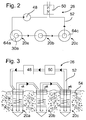
- FIG. 2 shows in plan view a schematic representation of three ground probes 20a
- FIG. 3 shows an arrangement of three ground probes 20a, 20b, 20c in series in a side view.
- the representation is less schematic, in particular, the lines 52 are clearly recognizable as such.
- FIG. 4 shows exemplary partial ring discs 76a-76e. These enclose in the inserted state, the inner tube 30 having an outer diameter d1, a center mt and an inner edge 78.
- the partial annular discs 76 can be connected in any manner with the inner tube 30, for example, welded or glued.
- the components of the Erdsondenfluidturbulators can be made of the same material, preferably made of thermoplastic Kuststoff, such as the inner tube 30 accordingly be, whereby a slight connection between the annular discs 76 and / or the annular discs 80 is ensured with the inner tube 30.
- the outer diameter d1 of the partial annular disc 76 is selected to be slightly smaller than the inner diameter of the outer tube 32. On the one hand this simplifies insertion of the inner tube 30 together with fixed partial annular discs 76 into the outer tube 32, on the other hand the partial annular discs 76 thereby act as spacers between the outer tube 32 and the inner tube 30, or support the two against each other.
- FIG. 5 shows a schematic representation of Operationnturbolators 84 in the mounted state.
- this consists of five partial annular discs 76a-76e, whose outer diameter d1 are smaller than the inner diameter of the outer tube 32.
- the partial annular discs 76a, 76d and 76e are preferably partial annular discs with a center angle of about 180 °, thus forming approximately half annular discs.
- the partial annular discs 76b and 76c are partial annular discs of less than 180 °. Such is preferably made of a half-ring disc, the end of a ring disk sector is removed.
- the partial annular discs 76a, 76c and 76e are preferably arranged one above the other in the operating state such that, in a plan view, the partial annular discs 76c and 76e are covered by the partial annular disc 76a. Further, the partial annular discs 76a, 76c and 76e lie in planes which have similar angles with respect to an orthogonal plane to the longitudinal axis 44. Partial ring disks 76b and 76d are arranged in a similar manner to one another and lie opposite the partial annular disks 76a, 76c and 76e with respect to the longitudinal axis.
- the planes in which the partial ring discs 76b and 76d lie have a similar angle value with respect to the orthogonal plane, but with a different sign than the planes of the partial ring discs 76a, 76c and 76e. So you are inclined in the opposite direction, so to speak. An angle value of approximately 5 ° to 15 ° proves advantageous.
- the geometry of such a partial disc turbulator 84 is similar to a helix with recesses 88 (between partial annular discs 76b-76c and 76c-76d). As a result, the heat transfer fluid undergoes three flow directions when passing through this Sectionstubenturbolators 84. These flow directions and partial flows are through the Arrows in FIG. 5 indicated.
- a part of the heat transfer fluid passes through the sectionusionnturbulator 84 in the vertical direction between the outer tube inner surface 60 and the Generalusionnturbulator 84.
- a second part is detected by partial ring disc 76a of Operausionnturbulators 84 and thereby experiences an oblique, rotational direction.
- This is additionally split between partial annular discs 76b-76c and 76c-76d into two sub-flows.
- One part crosses the recesses resulting from the fact that two adjacent partial annular discs 76b-76c, 76c-76d can not be assembled into complete annular discs, but together have a center angle of less than 360 ° and maintain its rotational movement.
- the remainder flows vertically through the recesses 88, creating additional turbulence.
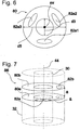
- FIG. 6 shows the schematic representation of an annular disc 80, with an outer diameter d5, an inner diameter d3, a center mr and three openings 82, wherein only one opening may be sufficient.
- the inner diameter d3 of the annular disc 80 is adapted to the outer diameter of the inner tube 30.
- the annular disc 80 similar to the above-described partial ring disc 76, can be fastened to the inner tube 30. However, this attachment preferably takes place in an orthogonal plane of the longitudinal axis 44.
- the outer diameter d5 of the annular disc 80 is preferably matched to the inner diameter da of the outer tube 32.
- the annular disc 80 thereby acts as a spacer between the outer tube 32 and the inner tube 30 and on the other hand, the vertical flow of the heat transfer fluid, in particular in the vicinity of the outer tube inner surface 60, thereby interrupted.
- the heat transfer fluid flows through the three orifice 82, thereby mixing the heat transfer fluid.
- FIG. 7 shows a schematic representation of an advantageous combination of two about the longitudinal axis 44 to each other rotated annular discs 80a and 80b, which are mutually, with a distance a in the direction of the longitudinal axis 44, respectively.
- Such an arrangement forms an annular disk pair 86.
- the present invention is not limited to the embodiment described above.
- the fastening of the annular disks 80 and / or the partial annular disks 76 can alternatively or additionally also take place on the outer pipe inner surface 60 of the outer pipe 32.
- the Operaringin 76 and / or the annular discs 80 then complete or partial distances from the inner tube 30 so that between them heat transfer fluid can flow in the axial direction.
- a helix which preferably has holes. The holes then generate the splitting of the rotary flow into a rotational and a vertical portion.
- stoppers 84 may be mounted on the part-disk turbulators. These generate additional turbulences of the oblique-rotational flow.
Landscapes
- Engineering & Computer Science (AREA)
- Life Sciences & Earth Sciences (AREA)
- Combustion & Propulsion (AREA)
- Sustainable Development (AREA)
- Sustainable Energy (AREA)
- Chemical & Material Sciences (AREA)
- General Life Sciences & Earth Sciences (AREA)
- Mechanical Engineering (AREA)
- General Engineering & Computer Science (AREA)
- Heat-Exchange Devices With Radiators And Conduit Assemblies (AREA)
- Geophysics And Detection Of Objects (AREA)
- Investigating Or Analyzing Materials By The Use Of Magnetic Means (AREA)
- Investigating Or Analyzing Materials By The Use Of Ultrasonic Waves (AREA)
- Buildings Adapted To Withstand Abnormal External Influences (AREA)
Priority Applications (3)
| Application Number | Priority Date | Filing Date | Title |
|---|---|---|---|
| SI201130738T SI2360438T1 (sl) | 2010-02-11 | 2011-02-11 | Fluidni turbulator za zemeljsko sondo |
| PL11154105T PL2360438T3 (pl) | 2010-02-11 | 2011-02-11 | Turbulator cieczy dla sondy ziemnej |
| HRP20160160TT HRP20160160T1 (hr) | 2010-02-11 | 2016-02-15 | Turbulator protoka za geotermalnu sondu |
Applications Claiming Priority (1)
| Application Number | Priority Date | Filing Date | Title |
|---|---|---|---|
| DE102010001823A DE102010001823A1 (de) | 2010-02-11 | 2010-02-11 | Erdsondenfluidturbulator |
Publications (3)
| Publication Number | Publication Date |
|---|---|
| EP2360438A2 EP2360438A2 (de) | 2011-08-24 |
| EP2360438A3 EP2360438A3 (de) | 2014-08-27 |
| EP2360438B1 true EP2360438B1 (de) | 2016-02-10 |
Family
ID=43901264
Family Applications (1)
| Application Number | Title | Priority Date | Filing Date |
|---|---|---|---|
| EP11154105.8A Active EP2360438B1 (de) | 2010-02-11 | 2011-02-11 | Fluidturbulator für Erdsonde |
Country Status (8)
| Country | Link |
|---|---|
| EP (1) | EP2360438B1 (sr) |
| DE (1) | DE102010001823A1 (sr) |
| DK (1) | DK2360438T3 (sr) |
| ES (1) | ES2563780T3 (sr) |
| HR (1) | HRP20160160T1 (sr) |
| PL (1) | PL2360438T3 (sr) |
| RS (1) | RS54604B1 (sr) |
| SI (1) | SI2360438T1 (sr) |
Families Citing this family (4)
| Publication number | Priority date | Publication date | Assignee | Title |
|---|---|---|---|---|
| CN105579786B (zh) * | 2013-09-24 | 2018-08-07 | 动力蓝控股公司 | 具有混合元件的地热探头 |
| DE202014102027U1 (de) | 2014-04-30 | 2015-08-03 | Klaus Knof | Erdsonde |
| DE102016109063A1 (de) | 2016-05-17 | 2017-11-23 | Anton LEDWON | Erdwärmesonde und Verfahren zur Längenanpassung einer Erdwärmesonde |
| DE102021108225A1 (de) * | 2021-03-31 | 2022-10-06 | Dynamic Blue Holding Gmbh | Strömungsleitelement für Kaltwärmenetze |
Family Cites Families (5)
| Publication number | Priority date | Publication date | Assignee | Title |
|---|---|---|---|---|
| DE3000157C2 (de) * | 1980-01-04 | 1984-05-17 | Klaus 3101 Hornbostel Prenzler | Wärmetauschervorrichtung zur Gewinnung von Wärmeenergie aus dem Erdreich |
| JP2004340463A (ja) * | 2003-05-15 | 2004-12-02 | K & S Japan Kk | 地熱を利用した空調装置 |
| EP2034252B1 (de) * | 2007-09-08 | 2015-11-11 | Dynamic Blue Holding GmbH | Erdsondenwärmekreislauf |
| DE102008002048B4 (de) | 2008-05-28 | 2011-03-10 | Koenig & Bauer Aktiengesellschaft | Verwendung einer Reinigungsanlagen zum Reinigen einer oder mehrere Druckwerkszylinder einer Druckeinheit einer Druckmaschine |
| DE102008036524B4 (de) * | 2008-08-06 | 2010-07-01 | Rausch Gmbh | Sondenkopf, Sonde und Verfahren zum Austausch von Wärmeenergie |
-
2010
- 2010-02-11 DE DE102010001823A patent/DE102010001823A1/de not_active Ceased
-
2011
- 2011-02-11 PL PL11154105T patent/PL2360438T3/pl unknown
- 2011-02-11 ES ES11154105.8T patent/ES2563780T3/es active Active
- 2011-02-11 SI SI201130738T patent/SI2360438T1/sl unknown
- 2011-02-11 DK DK11154105.8T patent/DK2360438T3/en active
- 2011-02-11 EP EP11154105.8A patent/EP2360438B1/de active Active
- 2011-02-11 RS RS20160084A patent/RS54604B1/sr unknown
-
2016
- 2016-02-15 HR HRP20160160TT patent/HRP20160160T1/hr unknown
Also Published As
| Publication number | Publication date |
|---|---|
| SI2360438T1 (sl) | 2016-04-29 |
| PL2360438T3 (pl) | 2016-06-30 |
| DE102010001823A1 (de) | 2011-08-11 |
| EP2360438A2 (de) | 2011-08-24 |
| RS54604B1 (sr) | 2016-08-31 |
| DK2360438T3 (en) | 2016-04-18 |
| ES2563780T3 (es) | 2016-03-16 |
| HRP20160160T1 (hr) | 2016-03-11 |
| EP2360438A3 (de) | 2014-08-27 |
Similar Documents
| Publication | Publication Date | Title |
|---|---|---|
| EP2034252B1 (de) | Erdsondenwärmekreislauf | |
| EP2360438B1 (de) | Fluidturbulator für Erdsonde | |
| EP0386176B1 (de) | Anlage zum austausch von energie zwischen erdreich und einem energieaustauscher | |
| EP3193117B1 (de) | Wärmetauschervorrichtung | |
| DE102010005992A1 (de) | Speicher zum temperaturgeschichteten Speichern von warmen Flüssigkeiten unterschiedlicher Temperatur | |
| EP3748254B1 (de) | Geothermiewärmetauscheranordnung umfassend wärmetauscherschraubpfosten | |
| DE2333839A1 (de) | Stroemungsdrosseleinrichtung | |
| DE102005020887B3 (de) | Gewendelter Wärmetauscher für Erdwärme | |
| WO2009129778A2 (de) | Modular aufgebauter sondenfuss und seine komponenten | |
| WO2014000852A1 (de) | Wärmemanagementsystem | |
| DE102014113750B4 (de) | Speichersonde mit Vermischungskörpern | |
| EP2060860B1 (de) | Geothermiesonde und Verfahren zu deren Installation | |
| EP4067670A1 (de) | Strömungsleitelement für kaltwärmenetze | |
| DE19810713C2 (de) | Kernbohrvorrichtung, Vorrichtung zum Einstecken in ein Kronenrohr und Verfahren zur Kühlung einer Bohrstelle | |
| EP0755497A1 (de) | Anlage zum austausch von energie zwischen erdreich und einem energietauscher | |
| DE102010008710B4 (de) | Verfahren zum Verlegen von Geothermiesonden und Geothermiesondengewerk | |
| DE29912335U1 (de) | Erdsonde | |
| WO2016030076A1 (de) | Isolierende rohrleitung, verwendung einer isolierenden rohrleitung, verfahren zu deren herstellung und erdwärmesonde | |
| DE1800852A1 (de) | Filterstrang fuer Rohrbrunnen | |
| WO2013091853A1 (de) | Erdwärmesondenanordnung | |
| EP1580397B1 (de) | Bohrspitze | |
| DE2603350A1 (de) | Wandkonstruktion fuer kassenschraenke o.dgl. | |
| DE202012004408U1 (de) | Massivabsorber in modularer Bauweise | |
| DE102010007662A1 (de) | Geothermieverteiler | |
| DE102010019728A1 (de) | Wärmetauschervorrichtung, Verwendung, Wärmetauscheranordnung |
Legal Events
| Date | Code | Title | Description |
|---|---|---|---|
| PUAI | Public reference made under article 153(3) epc to a published international application that has entered the european phase |
Free format text: ORIGINAL CODE: 0009012 |
|
| PUAI | Public reference made under article 153(3) epc to a published international application that has entered the european phase |
Free format text: ORIGINAL CODE: 0009012 |
|
| AK | Designated contracting states |
Kind code of ref document: A2 Designated state(s): AL AT BE BG CH CY CZ DE DK EE ES FI FR GB GR HR HU IE IS IT LI LT LU LV MC MK MT NL NO PL PT RO RS SE SI SK SM TR |
|
| AX | Request for extension of the european patent |
Extension state: BA ME |
|
| RIC1 | Information provided on ipc code assigned before grant |
Ipc: F24J 3/08 20060101AFI20140407BHEP |
|
| RAP1 | Party data changed (applicant data changed or rights of an application transferred) |
Owner name: DYNAMIC BLUE HOLDING GMBH |
|
| RIN1 | Information on inventor provided before grant (corrected) |
Inventor name: DYNAMIC BLUE HOLDING GMBH |
|
| PUAL | Search report despatched |
Free format text: ORIGINAL CODE: 0009013 |
|
| AK | Designated contracting states |
Kind code of ref document: A3 Designated state(s): AL AT BE BG CH CY CZ DE DK EE ES FI FR GB GR HR HU IE IS IT LI LT LU LV MC MK MT NL NO PL PT RO RS SE SI SK SM TR |
|
| AX | Request for extension of the european patent |
Extension state: BA ME |
|
| RIC1 | Information provided on ipc code assigned before grant |
Ipc: F24J 3/08 20060101AFI20140718BHEP |
|
| 17P | Request for examination filed |
Effective date: 20150226 |
|
| RBV | Designated contracting states (corrected) |
Designated state(s): AL AT BE BG CH CY CZ DE DK EE ES FI FR GB GR HR HU IE IS IT LI LT LU LV MC MK MT NL NO PL PT RO RS SE SI SK SM TR |
|
| GRAP | Despatch of communication of intention to grant a patent |
Free format text: ORIGINAL CODE: EPIDOSNIGR1 |
|
| INTG | Intention to grant announced |
Effective date: 20150730 |
|
| GRAS | Grant fee paid |
Free format text: ORIGINAL CODE: EPIDOSNIGR3 |
|
| GRAA | (expected) grant |
Free format text: ORIGINAL CODE: 0009210 |
|
| RIN1 | Information on inventor provided before grant (corrected) |
Inventor name: LEDWON, ANTON |
|
| AK | Designated contracting states |
Kind code of ref document: B1 Designated state(s): AL AT BE BG CH CY CZ DE DK EE ES FI FR GB GR HR HU IE IS IT LI LT LU LV MC MK MT NL NO PL PT RO RS SE SI SK SM TR |
|
| REG | Reference to a national code |
Ref country code: GB Ref legal event code: FG4D Free format text: NOT ENGLISH |
|
| REG | Reference to a national code |
Ref country code: HR Ref legal event code: TUEP Ref document number: P20160160 Country of ref document: HR Ref country code: AT Ref legal event code: REF Ref document number: 774856 Country of ref document: AT Kind code of ref document: T Effective date: 20160215 Ref country code: CH Ref legal event code: EP |
|
| REG | Reference to a national code |
Ref country code: RO Ref legal event code: EPE |
|
| REG | Reference to a national code |
Ref country code: SE Ref legal event code: TRGR |
|
| REG | Reference to a national code |
Ref country code: IE Ref legal event code: FG4D Free format text: LANGUAGE OF EP DOCUMENT: GERMAN |
|
| REG | Reference to a national code |
Ref country code: HR Ref legal event code: T1PR Ref document number: P20160160 Country of ref document: HR |
|
| REG | Reference to a national code |
Ref country code: ES Ref legal event code: FG2A Ref document number: 2563780 Country of ref document: ES Kind code of ref document: T3 Effective date: 20160316 |
|
| REG | Reference to a national code |
Ref country code: DE Ref legal event code: R096 Ref document number: 502011008832 Country of ref document: DE |
|
| REG | Reference to a national code |
Ref country code: FR Ref legal event code: PLFP Year of fee payment: 6 |
|
| REG | Reference to a national code |
Ref country code: NL Ref legal event code: FP |
|
| REG | Reference to a national code |
Ref country code: DK Ref legal event code: T3 Effective date: 20160411 |
|
| REG | Reference to a national code |
Ref country code: LT Ref legal event code: MG4D |
|
| PG25 | Lapsed in a contracting state [announced via postgrant information from national office to epo] |
Ref country code: GR Free format text: LAPSE BECAUSE OF FAILURE TO SUBMIT A TRANSLATION OF THE DESCRIPTION OR TO PAY THE FEE WITHIN THE PRESCRIBED TIME-LIMIT Effective date: 20160511 Ref country code: FI Free format text: LAPSE BECAUSE OF FAILURE TO SUBMIT A TRANSLATION OF THE DESCRIPTION OR TO PAY THE FEE WITHIN THE PRESCRIBED TIME-LIMIT Effective date: 20160210 Ref country code: NO Free format text: LAPSE BECAUSE OF FAILURE TO SUBMIT A TRANSLATION OF THE DESCRIPTION OR TO PAY THE FEE WITHIN THE PRESCRIBED TIME-LIMIT Effective date: 20160510 |
|
| PG25 | Lapsed in a contracting state [announced via postgrant information from national office to epo] |
Ref country code: PT Free format text: LAPSE BECAUSE OF FAILURE TO SUBMIT A TRANSLATION OF THE DESCRIPTION OR TO PAY THE FEE WITHIN THE PRESCRIBED TIME-LIMIT Effective date: 20160613 Ref country code: LT Free format text: LAPSE BECAUSE OF FAILURE TO SUBMIT A TRANSLATION OF THE DESCRIPTION OR TO PAY THE FEE WITHIN THE PRESCRIBED TIME-LIMIT Effective date: 20160210 Ref country code: IS Free format text: LAPSE BECAUSE OF FAILURE TO SUBMIT A TRANSLATION OF THE DESCRIPTION OR TO PAY THE FEE WITHIN THE PRESCRIBED TIME-LIMIT Effective date: 20160610 Ref country code: LV Free format text: LAPSE BECAUSE OF FAILURE TO SUBMIT A TRANSLATION OF THE DESCRIPTION OR TO PAY THE FEE WITHIN THE PRESCRIBED TIME-LIMIT Effective date: 20160210 |
|
| PG25 | Lapsed in a contracting state [announced via postgrant information from national office to epo] |
Ref country code: EE Free format text: LAPSE BECAUSE OF FAILURE TO SUBMIT A TRANSLATION OF THE DESCRIPTION OR TO PAY THE FEE WITHIN THE PRESCRIBED TIME-LIMIT Effective date: 20160210 |
|
| REG | Reference to a national code |
Ref country code: DE Ref legal event code: R097 Ref document number: 502011008832 Country of ref document: DE |
|
| PG25 | Lapsed in a contracting state [announced via postgrant information from national office to epo] |
Ref country code: SM Free format text: LAPSE BECAUSE OF FAILURE TO SUBMIT A TRANSLATION OF THE DESCRIPTION OR TO PAY THE FEE WITHIN THE PRESCRIBED TIME-LIMIT Effective date: 20160210 Ref country code: SK Free format text: LAPSE BECAUSE OF FAILURE TO SUBMIT A TRANSLATION OF THE DESCRIPTION OR TO PAY THE FEE WITHIN THE PRESCRIBED TIME-LIMIT Effective date: 20160210 |
|
| REG | Reference to a national code |
Ref country code: IE Ref legal event code: MM4A |
|
| PLBE | No opposition filed within time limit |
Free format text: ORIGINAL CODE: 0009261 |
|
| STAA | Information on the status of an ep patent application or granted ep patent |
Free format text: STATUS: NO OPPOSITION FILED WITHIN TIME LIMIT |
|
| 26N | No opposition filed |
Effective date: 20161111 |
|
| PG25 | Lapsed in a contracting state [announced via postgrant information from national office to epo] |
Ref country code: IE Free format text: LAPSE BECAUSE OF NON-PAYMENT OF DUE FEES Effective date: 20160211 |
|
| REG | Reference to a national code |
Ref country code: FR Ref legal event code: PLFP Year of fee payment: 7 |
|
| PG25 | Lapsed in a contracting state [announced via postgrant information from national office to epo] |
Ref country code: BG Free format text: LAPSE BECAUSE OF FAILURE TO SUBMIT A TRANSLATION OF THE DESCRIPTION OR TO PAY THE FEE WITHIN THE PRESCRIBED TIME-LIMIT Effective date: 20160510 |
|
| PGFP | Annual fee paid to national office [announced via postgrant information from national office to epo] |
Ref country code: DK Payment date: 20170222 Year of fee payment: 7 Ref country code: PL Payment date: 20170127 Year of fee payment: 7 Ref country code: NL Payment date: 20170220 Year of fee payment: 7 Ref country code: AT Payment date: 20170217 Year of fee payment: 7 Ref country code: BE Payment date: 20170220 Year of fee payment: 7 |
|
| PG25 | Lapsed in a contracting state [announced via postgrant information from national office to epo] |
Ref country code: MT Free format text: LAPSE BECAUSE OF FAILURE TO SUBMIT A TRANSLATION OF THE DESCRIPTION OR TO PAY THE FEE WITHIN THE PRESCRIBED TIME-LIMIT Effective date: 20160210 |
|
| REG | Reference to a national code |
Ref country code: DE Ref legal event code: R079 Ref document number: 502011008832 Country of ref document: DE Free format text: PREVIOUS MAIN CLASS: F24J0003080000 Ipc: F24T0010000000 |
|
| REG | Reference to a national code |
Ref country code: FR Ref legal event code: PLFP Year of fee payment: 8 |
|
| PGFP | Annual fee paid to national office [announced via postgrant information from national office to epo] |
Ref country code: CH Payment date: 20180221 Year of fee payment: 8 Ref country code: RO Payment date: 20180130 Year of fee payment: 8 |
|
| PG25 | Lapsed in a contracting state [announced via postgrant information from national office to epo] |
Ref country code: CY Free format text: LAPSE BECAUSE OF FAILURE TO SUBMIT A TRANSLATION OF THE DESCRIPTION OR TO PAY THE FEE WITHIN THE PRESCRIBED TIME-LIMIT Effective date: 20160210 Ref country code: HU Free format text: LAPSE BECAUSE OF FAILURE TO SUBMIT A TRANSLATION OF THE DESCRIPTION OR TO PAY THE FEE WITHIN THE PRESCRIBED TIME-LIMIT; INVALID AB INITIO Effective date: 20110211 |
|
| PGFP | Annual fee paid to national office [announced via postgrant information from national office to epo] |
Ref country code: SE Payment date: 20180222 Year of fee payment: 8 |
|
| PG25 | Lapsed in a contracting state [announced via postgrant information from national office to epo] |
Ref country code: MC Free format text: LAPSE BECAUSE OF FAILURE TO SUBMIT A TRANSLATION OF THE DESCRIPTION OR TO PAY THE FEE WITHIN THE PRESCRIBED TIME-LIMIT Effective date: 20160210 Ref country code: LU Free format text: LAPSE BECAUSE OF NON-PAYMENT OF DUE FEES Effective date: 20160211 Ref country code: MK Free format text: LAPSE BECAUSE OF FAILURE TO SUBMIT A TRANSLATION OF THE DESCRIPTION OR TO PAY THE FEE WITHIN THE PRESCRIBED TIME-LIMIT Effective date: 20160210 Ref country code: TR Free format text: LAPSE BECAUSE OF FAILURE TO SUBMIT A TRANSLATION OF THE DESCRIPTION OR TO PAY THE FEE WITHIN THE PRESCRIBED TIME-LIMIT Effective date: 20160210 |
|
| REG | Reference to a national code |
Ref country code: DK Ref legal event code: EBP Effective date: 20180228 |
|
| REG | Reference to a national code |
Ref country code: NL Ref legal event code: MM Effective date: 20180301 |
|
| REG | Reference to a national code |
Ref country code: AT Ref legal event code: MM01 Ref document number: 774856 Country of ref document: AT Kind code of ref document: T Effective date: 20180211 |
|
| PG25 | Lapsed in a contracting state [announced via postgrant information from national office to epo] |
Ref country code: AL Free format text: LAPSE BECAUSE OF FAILURE TO SUBMIT A TRANSLATION OF THE DESCRIPTION OR TO PAY THE FEE WITHIN THE PRESCRIBED TIME-LIMIT Effective date: 20160210 |
|
| REG | Reference to a national code |
Ref country code: BE Ref legal event code: MM Effective date: 20180228 |
|
| PG25 | Lapsed in a contracting state [announced via postgrant information from national office to epo] |
Ref country code: AT Free format text: LAPSE BECAUSE OF NON-PAYMENT OF DUE FEES Effective date: 20180211 |
|
| PG25 | Lapsed in a contracting state [announced via postgrant information from national office to epo] |
Ref country code: NL Free format text: LAPSE BECAUSE OF NON-PAYMENT OF DUE FEES Effective date: 20180301 |
|
| PG25 | Lapsed in a contracting state [announced via postgrant information from national office to epo] |
Ref country code: DK Free format text: LAPSE BECAUSE OF NON-PAYMENT OF DUE FEES Effective date: 20180228 |
|
| PG25 | Lapsed in a contracting state [announced via postgrant information from national office to epo] |
Ref country code: BE Free format text: LAPSE BECAUSE OF NON-PAYMENT OF DUE FEES Effective date: 20180228 |
|
| REG | Reference to a national code |
Ref country code: HR Ref legal event code: ODRP Ref document number: P20160160 Country of ref document: HR Payment date: 20190305 Year of fee payment: 9 |
|
| PGFP | Annual fee paid to national office [announced via postgrant information from national office to epo] |
Ref country code: IT Payment date: 20190226 Year of fee payment: 9 Ref country code: ES Payment date: 20190319 Year of fee payment: 9 |
|
| PGFP | Annual fee paid to national office [announced via postgrant information from national office to epo] |
Ref country code: TR Payment date: 20190129 Year of fee payment: 8 |
|
| REG | Reference to a national code |
Ref country code: CH Ref legal event code: PL |
|
| REG | Reference to a national code |
Ref country code: SE Ref legal event code: EUG |
|
| PG25 | Lapsed in a contracting state [announced via postgrant information from national office to epo] |
Ref country code: RO Free format text: LAPSE BECAUSE OF NON-PAYMENT OF DUE FEES Effective date: 20190211 Ref country code: SE Free format text: LAPSE BECAUSE OF NON-PAYMENT OF DUE FEES Effective date: 20190212 |
|
| PG25 | Lapsed in a contracting state [announced via postgrant information from national office to epo] |
Ref country code: PL Free format text: LAPSE BECAUSE OF NON-PAYMENT OF DUE FEES Effective date: 20180211 |
|
| PG25 | Lapsed in a contracting state [announced via postgrant information from national office to epo] |
Ref country code: CH Free format text: LAPSE BECAUSE OF NON-PAYMENT OF DUE FEES Effective date: 20190228 Ref country code: LI Free format text: LAPSE BECAUSE OF NON-PAYMENT OF DUE FEES Effective date: 20190228 |
|
| REG | Reference to a national code |
Ref country code: HR Ref legal event code: PBON Ref document number: P20160160 Country of ref document: HR Effective date: 20200211 |
|
| PG25 | Lapsed in a contracting state [announced via postgrant information from national office to epo] |
Ref country code: CZ Free format text: LAPSE BECAUSE OF NON-PAYMENT OF DUE FEES Effective date: 20200211 |
|
| PG25 | Lapsed in a contracting state [announced via postgrant information from national office to epo] |
Ref country code: HR Free format text: LAPSE BECAUSE OF NON-PAYMENT OF DUE FEES Effective date: 20200211 |
|
| REG | Reference to a national code |
Ref country code: ES Ref legal event code: FD2A Effective date: 20210705 |
|
| PG25 | Lapsed in a contracting state [announced via postgrant information from national office to epo] |
Ref country code: ES Free format text: LAPSE BECAUSE OF NON-PAYMENT OF DUE FEES Effective date: 20200212 |
|
| PG25 | Lapsed in a contracting state [announced via postgrant information from national office to epo] |
Ref country code: IT Free format text: LAPSE BECAUSE OF NON-PAYMENT OF DUE FEES Effective date: 20200211 |
|
| PGFP | Annual fee paid to national office [announced via postgrant information from national office to epo] |
Ref country code: SI Payment date: 20250203 Year of fee payment: 15 |
|
| PGFP | Annual fee paid to national office [announced via postgrant information from national office to epo] |
Ref country code: FR Payment date: 20250219 Year of fee payment: 15 |
|
| PGFP | Annual fee paid to national office [announced via postgrant information from national office to epo] |
Ref country code: GB Payment date: 20250220 Year of fee payment: 15 |
|
| PGFP | Annual fee paid to national office [announced via postgrant information from national office to epo] |
Ref country code: RS Payment date: 20250211 Year of fee payment: 15 |
|
| PGFP | Annual fee paid to national office [announced via postgrant information from national office to epo] |
Ref country code: DE Payment date: 20260217 Year of fee payment: 16 |