EP2360549A2 - Steuervorrichtung - Google Patents
Steuervorrichtung Download PDFInfo
- Publication number
- EP2360549A2 EP2360549A2 EP10006772A EP10006772A EP2360549A2 EP 2360549 A2 EP2360549 A2 EP 2360549A2 EP 10006772 A EP10006772 A EP 10006772A EP 10006772 A EP10006772 A EP 10006772A EP 2360549 A2 EP2360549 A2 EP 2360549A2
- Authority
- EP
- European Patent Office
- Prior art keywords
- base frame
- control device
- bearing board
- rolling bar
- chamber
- Prior art date
- Legal status (The legal status is an assumption and is not a legal conclusion. Google has not performed a legal analysis and makes no representation as to the accuracy of the status listed.)
- Withdrawn
Links
Images


Classifications
-
- G—PHYSICS
- G06—COMPUTING OR CALCULATING; COUNTING
- G06F—ELECTRIC DIGITAL DATA PROCESSING
- G06F1/00—Details not covered by groups G06F3/00 - G06F13/00 and G06F21/00
- G06F1/16—Constructional details or arrangements
- G06F1/1613—Constructional details or arrangements for portable computers
- G06F1/1632—External expansion units, e.g. docking stations
-
- G—PHYSICS
- G06—COMPUTING OR CALCULATING; COUNTING
- G06F—ELECTRIC DIGITAL DATA PROCESSING
- G06F3/00—Input arrangements for transferring data to be processed into a form capable of being handled by the computer; Output arrangements for transferring data from processing unit to output unit, e.g. interface arrangements
- G06F3/01—Input arrangements or combined input and output arrangements for interaction between user and computer
- G06F3/03—Arrangements for converting the position or the displacement of a member into a coded form
- G06F3/033—Pointing devices displaced or positioned by the user, e.g. mice, trackballs, pens or joysticks; Accessories therefor
- G06F3/0354—Pointing devices displaced or positioned by the user, e.g. mice, trackballs, pens or joysticks; Accessories therefor with detection of two-dimensional [2D] relative movements between the device, or an operating part thereof, and a plane or surface, e.g. 2D mice, trackballs, pens or pucks
- G06F3/03547—Touch pads, in which fingers can move on a surface
-
- G—PHYSICS
- G06—COMPUTING OR CALCULATING; COUNTING
- G06F—ELECTRIC DIGITAL DATA PROCESSING
- G06F3/00—Input arrangements for transferring data to be processed into a form capable of being handled by the computer; Output arrangements for transferring data from processing unit to output unit, e.g. interface arrangements
- G06F3/01—Input arrangements or combined input and output arrangements for interaction between user and computer
- G06F3/03—Arrangements for converting the position or the displacement of a member into a coded form
- G06F3/033—Pointing devices displaced or positioned by the user, e.g. mice, trackballs, pens or joysticks; Accessories therefor
- G06F3/0362—Pointing devices displaced or positioned by the user, e.g. mice, trackballs, pens or joysticks; Accessories therefor with detection of one-dimensional [1D] translations or rotations of an operating part of the device, e.g. scroll wheels, sliders, knobs, rollers or belts
Definitions
- the present invention relates to cursor control technology and more particularly, to a control device, which comprises an angle-adjustable bearing board for supporting an electronic device and a trackball device operable by the user to control the cursor on the display screen of the electronic device.
- a computer has multiple functions, bringing convenience to the user.
- a computer may be equipped with a keyboard and/or mouse for controlling a cursor on a display screen for menu item selection, cursor dragging or other operations.
- a user may rest the wrist of the hand on the desk or a mouse pad and then move the computer mouse or click the button of the computer mouse with the fingers.
- the user when going to move the computer mouse over a big area, the user must lift the wrist from the desk or mouse pad. Excessive or improper use of a computer may cause pain in the wrist (the so-called carpal tunnel syndrome).
- wrist rests are created.
- a wrist rest is a device used to support the wrist while typing or when using a computer mouse.
- the present invention has been accomplished under the circumstances in view. It is one object of the present invention to provide a control device, which is orthopedically engineered for comfortable use. It is another object of the present invention to provide a control device, which facilitates heat dissipation.
- a control device comprises a base frame, a bearing board hinged to the base frame at the top for holding an electronic device, a bracket hinged to the bearing board for supporting the bearing board on the base frame in a sloping position, and a trackball device mounted in a front recess of the base frame in front of the bearing board for operation by the user to control the cursor on the display screen of the electronic device being carried on the bearing board.
- the bearing board carries at least one heat transfer member prepared from aluminum alloy or copper alloy for direct contact of the electronic device being placed on the bearing board for quick dissipation of waste heat from the electronic device.
- the base frame comprises an accommodation open chamber adapted for accommodating a power control module, a cooling fan and/or any supplementary cooler module means, and a cover plate covering the accommodation open chamber.
- the cover plate has a plurality of locating members arranged on the top side thereof.
- the bracket has coupling end portions disposed at one side and pivotally coupled to the bottom wall of the bearing board, and a support portion disposed at an opposite side and adapted for selectively stopping at the locating members to support the bearing board in one of a series of angular positions.
- the base frame has a cushion pad detachably mounted on the bottom wall thereof.
- the cushion pad When the control device is rested on the user's lap, the cushion pad provides an excellent shock absorbing and buffering effect so that the user can operate the electronic device comfortably.
- the cushion pad comprises a plurality of hook members bilaterally arranged at the top side thereof for mounting.
- the base frame comprises two retaining rod members adapted for engaging the hook members of the cushion pad to secure the cushion pad, and two operating knobs operable to release the retaining rod members from the hook members of the cushion pad.
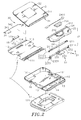
- a control device in accordance with the present invention comprising a base frame 1 , a trackball device 2 and a bearing board 3 .
- the base frame 1 has a front recess 10 , an accommodation open chamber 101 disposed behind the front recess 10, a cover plate 11 covered on the accommodation open chamber 101 behind the front recess 10 , a cushion pad 12 attached to the bottom side thereof and a positioning member 13 and a plurality of posts 14 disposed in the front recess 10.
- the cover plate 11 has at least one, for example, a plurality of pivot holders 111 mounted thereon at a front side and aligned in line adjacent to the front recess 10 , a recessed top bearing wall 113 and locating members 112 disposed in the rear side of the recessed top bearing wall 113 remote from the pivot holders 111 .
- the trackball device 2 is accommodated in the front recess 10 of the base frame 1 , comprising a rolling bar holder 21 , a rolling bar 22 , a circuit module 23 and a cover shell 24 .
- the rolling bar holder 21 consists of a first holder shell 211 and a second holder shell 212 .
- the first holder shell 211 has a rolling chamber 2111 defined therein for receiving the rolling bar 22, a through hole 2112 in communication between the rolling chamber 2111 and the front recess 10 of the base frame 1 , two retaining notches 2113 respectively located on the two distal ends thereof, and two push rods 2114 respectively fastened to the retaining notches 2113.
- the circuit module 23 comprises a circuit board 230 , a sensor module 231 installed in the circuit board 230 and aimed at the through hole 2112 of the first holder shell 211 and adapted for sensing the direction and amount of movement of the rolling bar 22 in the rolling chamber 2111, a plurality of control switches 232 mounted in the two distal ends of the second holder shell 212 and respectively kept in contact with the push rods 2114, a connection interface module 233 adapted for communication with an interface port 41 of an electronic device 4 (see FIG. 4 ) for signal transmission, and a touch panel 234 for touch control.
- the cover shell 24 is covered on the rolling bar holder 21 , having an opening 241 for the positioning of the first holder shell 211 of the rolling bar holder 21 and mounted with a shield 2411 that keeps the rolling bar 22 in the rolling chamber 2111 of the first holder shell 211 and allows a part of the rolling bar 22 to be exposed to the outside, a recessed chamber 242 disposed in front of the opening 241 for the mounting of the touch panel 234 , and a wrist rest pad 25 covered on the top wall thereof around the touch panel 234 in the recessed chamber 242 .
- the bearing board 3 comprises a plurality of knuckles 31 transversely arranged in line at the front side thereof and coupled to the at least one pivot member 111 of the cover plate 11 of the base frame 1 , an upright stop flange 311 extending along one side of the knuckles 31 , at least one heat transfer member 32 disposed remote from the knuckles 31 , two pivot connectors 33 symmetrically arranged at two opposite lateral sides relative to the at least one heat transfer member 32 and a bracket 34 coupled between the pivot connectors 33 and the base frame 1 .
- the bracket 34 comprises two coupling end portions 341 bilaterally disposed at one side and respectively pivotally coupled to the pivot connectors 33, and a support portion 342 disposed at an opposite side for positioning in the locating members 112 of the cover plate 11 .
- the bracket 34 can be biased relative to the cover plate 11 to lift the bearing board 3 from the cover plate 11 and to support the bearing board 3 above the cover plate 11 in a sloping position, leaving a heat dissipation space 30 between the cover plate 11 and the bearing board 3.
- the trackball device 2 When assembling the control device, put the trackball device 2 in the front recess 10 of the base frame 1 to force the second holder shell 212 of the rolling bar holder 21 into engagement with the positioning member 13 in the front recess 10 of the base frame 1 , and then fasten the circuit board 230 of the circuit module 23 to the posts 14 in the front recess 10 of the base frame 1 by, for example, screws.
- the circuit board 230 can be affixed to the rolling bar holder 21 by screws or any of a variety of other fastening measures.
- a pivot pin (not shown) through the knuckles 31 of the bearing board 3 and the pivot holders 111 of the cover plate 11 to pivotally couple the bearing board 3 to the cover plate 11 of the base frame 1 , and then turn the bearing board 3 downwards to let the bearing board 3 be closely attached to the cover plate 11 and the bracket 34 be received in the recessed top bearing wall 113 of the cover plate 11 .
- the accommodation open chamber 101 of the base frame 1 accommodates a power control module 15 .
- a cooling fan or cooler module may be mounted in the accommodation open chamber 101 of the base frame 1 for quick dissipation of waste heat during operation of the control device.
- the power control module 15 comprises a circuit board 151 and a battery 152 . Further, the power control module 15 is electrically connected to the circuit module 23 of the trackball device 2 to provide the circuit module 23 with the necessary working voltage.
- the cover plate 11 provides a battery chamber 114 , which accommodates the battery 152 of the power control module 15 .
- the battery chamber 114 is covered by a lid 115 .
- the cushion pad 12 has a plurality of hook members 121 bilaterally disposed at the top side thereof.
- the base frame 1 comprises two retaining rod members 161 adapted for engaging the hook members 121 to secure the cushion pad 12 , and two operating knobs 16 operable to release the retaining rod members 161 from the hook members 121 of the cushion pad 12 .
- the cushion pad 12 can be directly bonded to the base frame 1 .
- the cushion pad 12 can be prepared from EVA (ethylene vinyl acetate), PU (polyurethane), silicon rubber or any shock absorbing material.
- the sensor module 231 of the aforesaid circuit module 23 is adapted for sensing the direction and amount of movement (rotation and axial displacement) of the rolling bar 22 in the rolling chamber 2111. With respect to how the sensor module 231 generates and emits light and receives refracted image, and how the displacement of the rolling bar 22 in X-axis and Y-axis is counted and measured, it is of the known art and no further detailed description in this regard is necessary.
- the connection interface module 233 can be communicated with the interface port 41 of the electronic device 4 by a wired or wireless communication method for signal transmission, i.e., the connection interface module 233 can be a USB or PS2 interface, or a radio-frequency, Bluetooth or infrared communication interface.
- Bluetooth communication technique is employed for enabling the connection interface module 233 to communicate with the interface port 41 of the electronic device 4 wirelessly.
- a power switch 2331 and a Bluetooth switch 2332 are installed in the connection interface module 233 for power on/off control and Bluetooth function on/off control respectively.
- the bearing board 3 can be prepared from plastics, aluminum or copper.
- the heat transfer member 32 can be prepared from aluminum or copper alloy and made in the form of a heat transfer block or heat sink with radiation fins.
- the heat transfer member 32 can be formed integrally with the bearing board 3 .
- the heat transfer member 32 can be separately made and then affixed to the bearing board 3 with screws or by any of a variety of known mounting techniques.
- the control device of the present invention can be placed on a desk, table, or the user's lap.
- the control device turn the bearing board 3 upwards relative to the pivot holders 111 of the cover plate 11 , and then turn the bracket 34 outwards to stop the support portion 342 against the locating members 112 of the cover plate 11 .
- the locating members 112 of the cover plate 11 can be locating grooves or locating blocks aligned in a line.
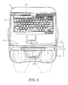
- the electronic device 4 to be supported on the bearing board 3 can be a mobile electronic device, such as notebook computer, PDA, multimedia device.
- the upright stop flange 311 of the bearing board 3 stops the electronic device 4 in place.
- the upright stop flange 311 may be covered with a layer of anti-slip pad or covering.
- the user can rest the wrists of the hands on the wrist rest pad 25 and operate the trackball device 2 in controlling the operation of the electronic device 4 .
- the cushion pad 12 provides an excellent shock absorbing and buffering effect so that the user can operate the electronic device 4 comfortably.
- the user can rotate the rolling bar 22 in the rolling chamber 2111 of the first holder shell 211 of the rolling bar holder 21 or move the rolling bar 22 in the rolling chamber 2111 in the axial direction conveniently with the fingers.
- the sensor module 231 of the circuit module 23 detects and measures the direction and amount of rotation or displacement of the rolling bar 22 for controlling direction and amount of displacement of the cursor on the display screen of the electronic device 4 .
- the sensor module 231 can sense rotation or displacement of the rolling bar 22 positively.
- the orthopedically engineered design of the control device enables the user to operate the electronic device 4 comfortably for a long period of time without causing hand pain or stiffness.
- the rolling bar 22 is prepared from a self-lubricating material for the advantage of low friction resistance and high stability.
- the rolling bar 22 When the user moves the rolling bar 22 axially leftward or rightward, the rolling bar 22 will push one push rod 2114 at the second holder shell 212 to trigger the corresponding control switch 232 , causing the control switch 232 to control displacement of the cursor on the display screen of the electronic device in X-axis direction.
- spring members may be provided at the bottom side of the first holder shell 211 to support the first holder shell 211 above the second holder shell 212 .
- the first holder shell 211 When the user presses the rolling bar 22 , the first holder shell 211 is lowered to compress the spring members and to further cause the corresponding control switch 232 at the circuit board 230 to be triggered in driving the cursor to click on a menu.
- the user can simultaneously rotate the rolling bar 22 or move it axially to scroll a webpage, to drag an object or to select a menu item on the display screen of the electronic device 4 .
- the first holder shell 211 is immediately returns to its former position above the second holder shell 212 by the spring members.
- the touch panel 234 of the circuit module 23 is exposed to the outside of the rolling bar holder 21 , having a plurality of function keys for different input modes, such as press button mode, webpage scroll mode, drag mode or cursor control mode.
- the user can touch the touch panel 234 with the fingers to move the cursor or picture on the display screen of the electronic device 4 , and to operate the function keys to run the functions like the functioning of the left button or right button of a computer mouse or to run "play", "pause”, “forward”, “backward”, “volume up” or “volume down” or to set brightness or contrast.
- the motherboard and electronic components of the electronic device 4 are arranged at the bottom side inside the electronic device 4 .
- the temperature inside the electronic device 4 will increase. Accumulation of waste heat in the electronic device 4 will affect normal functioning and stability of the internal electronic components.
- the invention avoids occurrence of this problem.
- the bottom wall of the electronic device 4 is kept in close contact with the heat transfer member 32 so that the heat transfer member 32 transfer waste heat from the electronic device 4 for quick dissipation by outside cooling air that circulates through the heat dissipation space 30 between the cover plate 11 and the bearing board 3 .
- the functioning of the heat transfer member 32 it is not necessary to install extra cooling fans or cooler module means, saving the space and minimizing the device weight to satisfy small size requirement.
- the invention provides a control device applicable for use with a notebook computer, mobile telephone or any of a variety of electronic devices 4 .
- the bracket 34 By means of the bracket 34 to support the bearing board 3 in a sloping position, the user can operate the electronic device 4 on the bearing board 3 or watch the display screen of the electronic device 4 conveniently and comfortably.
- the control device dissipates waste heat from the electronic device 4 rapidly.
- the locating members 112 may be spaced on the recessed top bearing wall 113 for selectively supporting the support portion 342 of the bracket 34 to hold the bracket 34 in one of a series of angles.
- gear means may be provided between the knuckles 31 of the bearing board 3 and the pivot holders 111 of the cover plate 11 of the base frame 1 and operated to adjust the angular position of the bearing board 3 relative to the cover plate 11 .
- mouse, trackball mouse, touch panel or any of a variety of other cursor control means may be used to substitute for the trackball device 2 .
- the rolling bar 22 can be made in the form of a trackball or any of a variety of other designs movable in X-axis and Y-axis directions for detection by the sensor module 231 and for enabling the detected signal to be transmitted to the electronic device 4 through the connection interface module 233 .
- FIGS. 1 ⁇ 5 A prototype of control device has been constructed with the features of FIGS. 1 ⁇ 5 .
- the control device functions smoothly to provide all of the features disclosed earlier.
Landscapes
- Engineering & Computer Science (AREA)
- Theoretical Computer Science (AREA)
- General Engineering & Computer Science (AREA)
- Human Computer Interaction (AREA)
- Physics & Mathematics (AREA)
- General Physics & Mathematics (AREA)
- Computer Hardware Design (AREA)
- Position Input By Displaying (AREA)
- Power Sources (AREA)
- Casings For Electric Apparatus (AREA)
Applications Claiming Priority (1)
| Application Number | Priority Date | Filing Date | Title |
|---|---|---|---|
| TW099203172U TWM383774U (en) | 2010-02-12 | 2010-02-12 | Operation and control apparatus |
Publications (1)
| Publication Number | Publication Date |
|---|---|
| EP2360549A2 true EP2360549A2 (de) | 2011-08-24 |
Family
ID=42829972
Family Applications (1)
| Application Number | Title | Priority Date | Filing Date |
|---|---|---|---|
| EP10006772A Withdrawn EP2360549A2 (de) | 2010-02-12 | 2010-06-30 | Steuervorrichtung |
Country Status (4)
| Country | Link |
|---|---|
| US (1) | US20110199306A1 (de) |
| EP (1) | EP2360549A2 (de) |
| JP (1) | JP3162956U (de) |
| TW (1) | TWM383774U (de) |
Cited By (1)
| Publication number | Priority date | Publication date | Assignee | Title |
|---|---|---|---|---|
| CN107045396A (zh) * | 2017-03-27 | 2017-08-15 | 深圳市苏恒科技有限公司 | 一种多维运动鼠标 |
Families Citing this family (7)
| Publication number | Priority date | Publication date | Assignee | Title |
|---|---|---|---|---|
| US8823644B2 (en) | 2009-12-08 | 2014-09-02 | Contour Design Inc. | Inner-sensor based pointing device |
| US20120162071A1 (en) * | 2010-02-22 | 2012-06-28 | Liang Hsu | Control device |
| DK179691B1 (en) | 2013-02-05 | 2019-03-26 | Contour Design | Improved pointing device |
| WO2016179768A1 (en) | 2015-05-08 | 2016-11-17 | Contour Design, Inc. | Pointing device bracket assembly and system |
| US11023053B2 (en) | 2016-11-11 | 2021-06-01 | Contour Innovations Llc | Inner-sensor pointing device system |
| CN109599803B (zh) * | 2018-11-23 | 2020-06-05 | 南京六六创业科技有限公司 | 一种办公用线路固定整理装置 |
| US12085899B2 (en) * | 2021-06-06 | 2024-09-10 | International Business Machines Corporation | Computer driven external digital crown for smartwatch |
Family Cites Families (13)
| Publication number | Priority date | Publication date | Assignee | Title |
|---|---|---|---|---|
| JP2001144485A (ja) * | 1999-11-11 | 2001-05-25 | Internatl Business Mach Corp <Ibm> | 電子機器の放熱構造、電子機器及びコンピュータ装置 |
| US6392877B1 (en) * | 2000-06-05 | 2002-05-21 | Richard J. Iredale | Laptop computer display mounting |
| DK2163969T3 (da) * | 2000-11-21 | 2014-11-10 | Contour Design Inc | Ergonomisk pegeindretning |
| US7209355B2 (en) * | 2002-05-15 | 2007-04-24 | Matsushita Electric Industrial Co., Ltd. | Cooling device and an electronic apparatus including the same |
| TW200514491A (en) * | 2003-06-13 | 2005-04-16 | Humanscale Corp | Laptop holder |
| TWM245484U (en) * | 2003-11-10 | 2004-10-01 | Tatung Co | Structure for locking a portable computer to its docket |
| TWM246678U (en) * | 2003-12-17 | 2004-10-11 | Tatung Co | Erecting structure of portable computer |
| US7336258B1 (en) * | 2004-01-05 | 2008-02-26 | Goetsch Stephen R | Adjustable computer mouse stand |
| US20070258206A1 (en) * | 2006-05-02 | 2007-11-08 | Tai-Chi Huang | Heat dissipating base for laptops |
| US7911784B2 (en) * | 2008-06-23 | 2011-03-22 | Bradley Jones | Mobile computer stand with integrated keyboard |
| US7866623B2 (en) * | 2008-10-21 | 2011-01-11 | Sony Corporation | Computer retail display stand |
| US8108970B2 (en) * | 2009-07-28 | 2012-02-07 | Shin Zu Shing Co., Ltd. | Hinge mechanism and an electronic device therewith |
| TWM401808U (en) * | 2010-09-15 | 2011-04-11 | Ektouch Co Ltd | Manipulation control device |
-
2010
- 2010-02-12 TW TW099203172U patent/TWM383774U/zh not_active IP Right Cessation
- 2010-06-17 US US12/801,611 patent/US20110199306A1/en not_active Abandoned
- 2010-06-30 EP EP10006772A patent/EP2360549A2/de not_active Withdrawn
- 2010-07-12 JP JP2010004681U patent/JP3162956U/ja not_active Expired - Fee Related
Non-Patent Citations (1)
| Title |
|---|
| None |
Cited By (3)
| Publication number | Priority date | Publication date | Assignee | Title |
|---|---|---|---|---|
| CN107045396A (zh) * | 2017-03-27 | 2017-08-15 | 深圳市苏恒科技有限公司 | 一种多维运动鼠标 |
| WO2018176903A1 (zh) * | 2017-03-27 | 2018-10-04 | 深圳市苏恒科技有限公司 | 一种多维运动鼠标 |
| CN107045396B (zh) * | 2017-03-27 | 2020-03-10 | 深圳市苏恒科技有限公司 | 一种多维运动鼠标 |
Also Published As
| Publication number | Publication date |
|---|---|
| JP3162956U (ja) | 2010-09-24 |
| US20110199306A1 (en) | 2011-08-18 |
| TWM383774U (en) | 2010-07-01 |
Similar Documents
| Publication | Publication Date | Title |
|---|---|---|
| EP2360549A2 (de) | Steuervorrichtung | |
| US5565889A (en) | Pointing devices for a portable computer | |
| US7035094B2 (en) | Support assembly for a portable computer | |
| JP4323532B2 (ja) | カーソル制御装置 | |
| US20150049059A1 (en) | Actuating user interface for media player | |
| US20080316176A1 (en) | Portable computer system with extendable usb-powered i/o device | |
| US6724365B1 (en) | Scroll wheel device for portable computers | |
| US20110037693A1 (en) | Cursor control device | |
| EP2434374A2 (de) | Steuervorrichtung | |
| US9354666B2 (en) | Electronic device and operating method thereof | |
| EP3084550A1 (de) | Andocksystem | |
| US7894189B2 (en) | Portable computer with an expandable handle | |
| US8314771B2 (en) | Operation control device | |
| US6366274B1 (en) | Hand-held input devices for personal computer systems | |
| US7133021B2 (en) | Finger-fitting pointing device | |
| US20060164392A1 (en) | Integrated mouse and the keyboard device | |
| US20070139378A1 (en) | Wireless computer mouse and presenter having text capability | |
| AU2010100543A4 (en) | Control device | |
| CA2705981A1 (en) | Control device | |
| US8203532B2 (en) | Portable mouse attachable on a surface of an object | |
| US6304252B1 (en) | Methods for operating input devices for personal computer systems | |
| US20090002320A1 (en) | Keyboard With Surface for Computer Mouse Operation and Moveable Numeric Keypad | |
| EP2431843A2 (de) | Steuervorrichtung | |
| US20060279546A1 (en) | Keyboard with surface for computer mouse operation and moveable numeric keypad | |
| CN219800118U (zh) | 一种防抠防摔一体式蓝牙键盘 |
Legal Events
| Date | Code | Title | Description |
|---|---|---|---|
| PUAI | Public reference made under article 153(3) epc to a published international application that has entered the european phase |
Free format text: ORIGINAL CODE: 0009012 |
|
| PUAI | Public reference made under article 153(3) epc to a published international application that has entered the european phase |
Free format text: ORIGINAL CODE: 0009012 |
|
| AK | Designated contracting states |
Kind code of ref document: A2 Designated state(s): AL AT BE BG CH CY CZ DE DK EE ES FI FR GB GR HR HU IE IS IT LI LT LU LV MC MK MT NL NO PL PT RO SE SI SK SM TR |
|
| AX | Request for extension of the european patent |
Extension state: BA ME RS |
|
| RAP1 | Party data changed (applicant data changed or rights of an application transferred) |
Owner name: LIANG, HSU |
|
| STAA | Information on the status of an ep patent application or granted ep patent |
Free format text: STATUS: THE APPLICATION IS DEEMED TO BE WITHDRAWN |
|
| 18D | Application deemed to be withdrawn |
Effective date: 20140103 |