EP2360840A2 - Stereosignalverarbeitungseinheit - Google Patents
Stereosignalverarbeitungseinheit Download PDFInfo
- Publication number
- EP2360840A2 EP2360840A2 EP20110155258 EP11155258A EP2360840A2 EP 2360840 A2 EP2360840 A2 EP 2360840A2 EP 20110155258 EP20110155258 EP 20110155258 EP 11155258 A EP11155258 A EP 11155258A EP 2360840 A2 EP2360840 A2 EP 2360840A2
- Authority
- EP
- European Patent Office
- Prior art keywords
- signal
- level
- wide band
- signal level
- adjacent interference
- Prior art date
- Legal status (The legal status is an assumption and is not a legal conclusion. Google has not performed a legal analysis and makes no representation as to the accuracy of the status listed.)
- Withdrawn
Links
- 238000000034 method Methods 0.000 abstract description 4
- 230000010355 oscillation Effects 0.000 description 8
- 239000003990 capacitor Substances 0.000 description 7
- 238000010586 diagram Methods 0.000 description 6
- 230000002238 attenuated effect Effects 0.000 description 4
- 239000002131 composite material Substances 0.000 description 4
- 238000001514 detection method Methods 0.000 description 4
- 230000005236 sound signal Effects 0.000 description 3
- 230000003321 amplification Effects 0.000 description 2
- 238000003199 nucleic acid amplification method Methods 0.000 description 2
- 230000002411 adverse Effects 0.000 description 1
- 239000000284 extract Substances 0.000 description 1
- 239000004065 semiconductor Substances 0.000 description 1
Images


Classifications
-
- H—ELECTRICITY
- H04—ELECTRIC COMMUNICATION TECHNIQUE
- H04B—TRANSMISSION
- H04B1/00—Details of transmission systems, not covered by a single one of groups H04B3/00 - H04B13/00; Details of transmission systems not characterised by the medium used for transmission
- H04B1/06—Receivers
- H04B1/16—Circuits
- H04B1/1646—Circuits adapted for the reception of stereophonic signals
- H04B1/1661—Reduction of noise by manipulation of the baseband composite stereophonic signal or the decoded left and right channels
Definitions
- the present invention relates to a stereo signal processing circuit which decodes an L+R signal and an L-R signal from a received signal and obtains an L signal and an R signal by applying addition or subtraction between the L+R signal and the L-R signal.
- a predetermined reference signal which is determined according to a frequency of a desired station is mixed so that a signal from the desired station is converted into an intermediate frequency (IF) signal and a desired station signal is extracted from the IF signal.
- IF intermediate frequency
- a wide band AGC Auto Gain Control
- a narrow band AGC for attenuating the level of the received signal when the level of the extracted desired station signal is greater than or equal to a predetermined level
- the wide band AGC is operated according to the signal level after tuning.
- stereo broadcasting In FM broadcasting, stereo broadcasting is employed.
- a main signal (L+R signal) and a sub signal (L-R signal) are transmitted, and the receiver adds the L+R signal and the L-R signal to obtain the L signal and subtracts the L-R signal from the L+R signal to obtain the R signal, to replay the stereo signal.
- JP S61-69231 A and JP 2009-152873 A are related art documents of the present invention.
- a stereo signal processing circuit which decodes an L+R signal and an L-R signal from an input signal and obtains an L signal and an R signal through an addition and a subtraction between the L+R signal and the L-R signal
- the stereo signal processing circuit comprising an adjacent interference detecting unit which compares a signal level of a wide band signal which is a desired station signal of a relatively wide band and a signal level of a narrowband signal which is a desired station signal of a relatively narrow band, and judges that adjacent interference has occurred when the signal level of the narrow band signal is less than or equal to a predetermined signal level even though the signal level of the wide band signal is greater than or equal to a predetermined signal level, and an attenuating unit which attenuates the L-R signal and obtains a monophonic signal when the signal level of the narrow band signal is less than or equal to a predetermined signal level, wherein a signal level of the narrow band signal at which the attenuating unit starts attenuating
- the change to the monophonic signal can be started from a point where the signal level of the desired station signal is high, and the noise level of the output signal can be maintained low.
- FIGs. 1 and 2 are diagrams showing a structure of a signal processing unit of an FM radio receiver.
- FIG. 1 shows a structure from reception of a broadcast wave to obtaining a composite signal.
- the broadcast wave is received by an antenna 10, and is supplied to a variable amplifier 12 which is also called a low noise amplifier (LNA).
- LNA low noise amplifier
- a mixer 14 is connected to the variable amplifier 12.
- the mixer 14 mixes a signal from a local oscillator and the frequency of the desired station signal is frequency-converted (down-converted) to a predetermined intermediate frequency signal.
- the frequency-converted signal is supplied to a low-pass filter 16, where unnecessary high frequency components are removed.
- An output of the low-pass filter 16 is supplied to a variable amplifier 18 which is also called a post amplifier, and an output of the variable amplifier 18 is supplied to a band-pass filter 20.
- the band-pass filter 20 extracts an intermediate frequency, and the IF signal of the desired station is obtained.
- the IF Signal is detected and an audio signal is decoded.
- the IF signal is a desired station signal of a stereo broadcast, and is a composite signal including the main (L+R) signal and the sub (L-R) signal.
- the output of the low-pass filter 16 is supplied to a wide band AGC controller 22.
- the wide band AGC controller 22 detects a signal intensity of the output of the low-pass filter 16, and applies control such that, when the detected signal intensity is greater than or equal to a predetermined value, the output of the variable amplifier 12 is reduced.
- the received signal which is supplied from the antenna 10 may be attenuated by an attenuator provided inside the variable amplifier 12, or the amplification of the variable amplifier 12 may be changed.
- the output of the band-pass filter 20 is also supplied to a narrow band AGC controller 24.
- the narrow band AGC controller 24 detects a signal intensity of the output of the band-pass filter 20, and applies control such that when the detected signal intensity is greater than or equal to a predetermined value, the output of the variable amplifier 18 is reduced.
- the signal which is input may be attenuated by an attenuator provided inside the variable amplifier 18, or the amplification of the variable amplifier 18 may be changed.
- Signals from the wide band AGC controller 22 and the narrow band AGC controller 24 are supplied to an adjacent interference detecting unit 26.
- the adjacent interference detecting unit compares a signal intensity of the output of the band-pass filter 20 supplied to the narrow band AGC controller 24 (narrow band signal intensity) and a signal intensity of the output of the low-pass filter 16 supplied to the wide band AGC controller 22 (wide band signal intensity) , to detect adjacent interference.
- an adjacent interference detection signal is output when the wide band signal intensity is greater than or equal to a predetermined value and the narrow band signal intensity is less than or equal to a predetermined value.
- the adjacent interference detection signal is a signal which indicates the magnitude of a difference between the compared signals.
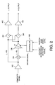
- FIG. 2 shows a circuit for obtaining left and right signals (L signal and R signal) from the composite signal.
- the obtained L signal and the obtained R signal are decoded to form an audio signal, which is used for driving a speaker.
- the composite signal for the IF signal of desired station which is output from the band-pass filter 20 is the main signal (L+R signal) in which the left signal L and the right signal R are added.
- this signal is amplified and decoded to obtain a monophonic signal.
- this signal is used as the main signal.
- the signal is amplified by an amplifier 30 and is then supplied to an adder 32.
- the output of the amplifier 30 is also supplied to a mixer 34 where a decode signal is mixed, and the signal is converted to the sub signal (L-R signal).
- An output of the mixer 34 is supplied to the adder 32 and a subtractor 38 through a variable amplifier 36.
- the L+R signal which is the output of the amplifier 30 is also supplied to the subtractor 38.
- an amount of attenuation of the sub signal is controlled by a control signal from a controller 44.
- the controller 44 adjusts the amount of attenuation of the sub signal at the variable amplifier 36 based on the adjacent interference detection signal which is supplied from the adjacent interference detecting unit 26 and a signal level of the narrow band signal which is supplied from the narrow band AGC controller 24.
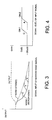
- the horizontal axis represents a signal level of the narrow band signal (desired station signal) and the horizontal axis represents an output level.
- the output level in this case represents a sum of the L signal and the R signal in FIG. 2 , but may alternatively be one of these signals.
- the output level is slightly suppressed when the signal level of the narrow band signal is very low, but at higher signal levels, the output level is adjusted to an approximate constant level. When the signal level of the narrow band signal is 0, all of the output becomes noise.
- the output level is controlled at an approximately constant level.
- the signal level of the narrow band signal is increased, the percentage of the broadcast wave of the desired station is gradually increased, and the noise level is reduced.
- the noise levels differ from each other. In FIG. 3 , this difference can be seen by a difference between noise (stereo) and noise (monophonic).
- the adjacent interference detecting unit 26 generates the detection signal such that when the signal level of the narrow band signal is reduced from a predetermined value, the output gradually transfers to the monophonic signal.
- the start level is divided into 3 stages, and the variable amplifier 36 is controlled according to the magnitude of the adjacent interference such that as the adjacent interference is increased, the device shifts to the monophonic configuration at a higher signal level of the narrow band signal.
- the device shifts to monophonic configuration at a relatively low input level as shown by c, and according to the degree of the adjacent interference, the device shifts to the monophonic configuration from a relatively high input level, as shown by b and a.
- the noise level can be reduced, and even when the input level is low, the SN ratio can be maintained at a relatively high level.
- FIG. 4 shows an example operation of the wide band AGC.
- the wide band AGC controller 22 attenuates the input signal when the input signal level is greater than or equal to a predetermined level.
- the attenuation of the input signal is changed according to the presence/absence of adjacent interference. That is, when there is no adjacent interference, the input signal is attenuated from a relatively low level as shown by B.
- the input level at which the attenuation of the input signal starts is increased as shown by A. In this manner, it is possible to prevent significant attenuation of the desired station signal when there is adjacent interference.
- the sub signal (L-R signal) is attenuated according to the adjacent interference.
- the sub signal which is the output of the mixer 34 is a signal of a certain frequency.
- the frequency characteristic of the sub signal it is possible to remove the influence of the adjacent interference, even though the signal level of the sub signal would be reduced. Therefore, it is also preferable to change the frequency characteristic of the sub signal in place of or in addition to the attenuation of the sub signal.
- the change of the frequency characteristic for example, it is known that as the input signal is weakened, the noise is raised from a relatively high frequency, and therefore, that a configuration is employed in which the frequency characteristic of the sub signal is shifted to the lower frequency side. In other words, by reducing the cut-off frequency of the low-pass filter, the influence of the adjacent interference can be reduced.
- FIG. 5 shows a portion of a tuning circuit in an AM radio.
- a received signal which is received by an antenna is supplied to a coil 50.
- an oscillator 54 is connected and a variable capacitor 56 is connected. Because the other end of the coil 52 and the other end of the variable capacitor 56 are connected to ground, the oscillator 54, variable capacitor 56, and coil 52 form an oscillation circuit which oscillates at an arbitrary frequency that is set by changing the capacitance of the variable capacitor 56.
- the antenna By causing the oscillation circuit to oscillate at a frequency of the desired station, the antenna can be tuned with the frequency of the desired station. Because a coil 58 is provided in addition to the coils 50 and 52, the received signal which is received by the antenna can be obtained at the coil 58.
- a filter 60 is provided for preventing AM inflow interference, and is a low-pass filter comprising a resistor 60a connected to one end of the coil 58 and a capacitor 60b which connects the other end of the resistor to ground.
- the coil 58 has one end connected through the filter 60 to a low noise amplifier 62 of a receiver circuit which processes a tuned signal and the other end connected to a reference power supply 64 which supplies a referenced voltage Vref.
- the antenna oscillation circuit is formed using the coil 58 for reception. Because of this, when the filter 60 is inserted, the oscillation frequency of the antenna oscillation circuit would be changed. Therefore, in the structure of the related art, the filter cannot be inserted. According to the present structure, the antenna oscillation circuit comprising the oscillator 54, variable capacitor 56, and coil 52 is separated from the coil 58 for obtaining the desired station signal. Because of this, it is possible to insert the filter 60 and effectively prevent the AM inflow interference without adversely affecting the oscillation frequency of the antenna oscillation circuit.
- a white rectangle represents a terminal of a semiconductor integrated circuit (IC), and the variable capacitor 56 can be included in the IC.
Landscapes
- Engineering & Computer Science (AREA)
- Computer Networks & Wireless Communication (AREA)
- Signal Processing (AREA)
- Noise Elimination (AREA)
- Control Of Amplification And Gain Control (AREA)
Applications Claiming Priority (1)
| Application Number | Priority Date | Filing Date | Title |
|---|---|---|---|
| JP2010036531A JP2011172188A (ja) | 2010-02-22 | 2010-02-22 | ステレオ信号処理回路 |
Publications (1)
| Publication Number | Publication Date |
|---|---|
| EP2360840A2 true EP2360840A2 (de) | 2011-08-24 |
Family
ID=44063875
Family Applications (1)
| Application Number | Title | Priority Date | Filing Date |
|---|---|---|---|
| EP20110155258 Withdrawn EP2360840A2 (de) | 2010-02-22 | 2011-02-21 | Stereosignalverarbeitungseinheit |
Country Status (4)
| Country | Link |
|---|---|
| US (1) | US8934634B2 (de) |
| EP (1) | EP2360840A2 (de) |
| JP (1) | JP2011172188A (de) |
| CN (1) | CN102163984B (de) |
Families Citing this family (2)
| Publication number | Priority date | Publication date | Assignee | Title |
|---|---|---|---|---|
| US9001941B2 (en) * | 2012-01-31 | 2015-04-07 | Analog Devices, Inc. | Method and apparatus to independently control front end gain and baseband gain |
| US12107673B2 (en) * | 2021-09-07 | 2024-10-01 | Qualcomm Incorporated | Jammer detection system |
Citations (2)
| Publication number | Priority date | Publication date | Assignee | Title |
|---|---|---|---|---|
| JPS6169231A (ja) | 1984-09-13 | 1986-04-09 | Clarion Co Ltd | 受信妨害排除回路 |
| JP2009152873A (ja) | 2007-12-20 | 2009-07-09 | Sanyo Electric Co Ltd | Fmデータ放送用チューナ |
Family Cites Families (6)
| Publication number | Priority date | Publication date | Assignee | Title |
|---|---|---|---|---|
| JP3992521B2 (ja) * | 2001-09-26 | 2007-10-17 | 三洋電機株式会社 | 隣接妨害検出装置および方法、ならびにその方法を利用可能な放送受信装置 |
| JP4539089B2 (ja) * | 2003-12-04 | 2010-09-08 | 株式会社村田製作所 | デジタルテレビ放送受信モジュール |
| JP2009021721A (ja) * | 2007-07-11 | 2009-01-29 | Sanyo Electric Co Ltd | Fmチューナ |
| JP4916974B2 (ja) * | 2007-08-03 | 2012-04-18 | オンセミコンダクター・トレーディング・リミテッド | Fmチューナ |
| JP2009081839A (ja) | 2007-09-04 | 2009-04-16 | Sanyo Electric Co Ltd | Fmチューナ |
| JP2009105727A (ja) * | 2007-10-24 | 2009-05-14 | Sanyo Electric Co Ltd | Fm受信機 |
-
2010
- 2010-02-22 JP JP2010036531A patent/JP2011172188A/ja active Pending
-
2011
- 2011-02-21 EP EP20110155258 patent/EP2360840A2/de not_active Withdrawn
- 2011-02-22 CN CN201110042988.4A patent/CN102163984B/zh not_active Expired - Fee Related
- 2011-02-22 US US13/032,216 patent/US8934634B2/en active Active
Patent Citations (2)
| Publication number | Priority date | Publication date | Assignee | Title |
|---|---|---|---|---|
| JPS6169231A (ja) | 1984-09-13 | 1986-04-09 | Clarion Co Ltd | 受信妨害排除回路 |
| JP2009152873A (ja) | 2007-12-20 | 2009-07-09 | Sanyo Electric Co Ltd | Fmデータ放送用チューナ |
Also Published As
| Publication number | Publication date |
|---|---|
| CN102163984A (zh) | 2011-08-24 |
| US20110206210A1 (en) | 2011-08-25 |
| US8934634B2 (en) | 2015-01-13 |
| CN102163984B (zh) | 2016-06-29 |
| JP2011172188A (ja) | 2011-09-01 |
Similar Documents
| Publication | Publication Date | Title |
|---|---|---|
| KR0160687B1 (ko) | 저잡음 증폭기를 갖는 영상신호 수신상치 | |
| US7756499B2 (en) | Receiver and amplification-gain controlling device thereof | |
| US8934634B2 (en) | Stereo signal processing circuit | |
| JP2005513903A (ja) | チューナ用の自動利得制御 | |
| JP5195234B2 (ja) | 受信装置及び受信方法 | |
| JP2018191302A (ja) | テレビジョン受信装置およびテレビジョン受信方法 | |
| KR100726782B1 (ko) | 지상파 디지털 멀티미디어 방송용/디지털 오디오 방송용Low-IF 수신기. | |
| JP2006217127A (ja) | 受信装置 | |
| CN100592767C (zh) | 调谐器 | |
| JP4135746B2 (ja) | 高周波信号受信装置 | |
| JP2010011402A (ja) | 受信装置及び受信方法 | |
| JP4409423B2 (ja) | Am受信機 | |
| US20080211970A1 (en) | Television reception circuit and television reception apparatus | |
| KR100930191B1 (ko) | 자동 이득 제어기능을 개선한 방송 수신 장치 | |
| JP4392009B2 (ja) | 地上波デジタルマルチメディア放送用/デジタルオーディオ放送用のLow−IF受信器 | |
| JPH06291688A (ja) | 受信機 | |
| US20090124228A1 (en) | Intermodulation disturbance detecting unit | |
| KR100560000B1 (ko) | 위성방송튜너회로 | |
| JP2004229170A (ja) | 受信機及び受信方法 | |
| KR100652961B1 (ko) | 채널전환속도를 향상시키는 방송수신장치 및 방송수신방법 | |
| KR20080036723A (ko) | 디지털 튜너 | |
| US20090111416A1 (en) | Intermodulation disturbance detecting circuit | |
| KR20070103586A (ko) | 위성파 튜너 | |
| JP2002368631A (ja) | Fm受信機 | |
| JP2007129576A (ja) | 移動受信端末装置 |
Legal Events
| Date | Code | Title | Description |
|---|---|---|---|
| PUAI | Public reference made under article 153(3) epc to a published international application that has entered the european phase |
Free format text: ORIGINAL CODE: 0009012 |
|
| 17P | Request for examination filed |
Effective date: 20110221 |
|
| AK | Designated contracting states |
Kind code of ref document: A2 Designated state(s): AL AT BE BG CH CY CZ DE DK EE ES FI FR GB GR HR HU IE IS IT LI LT LU LV MC MK MT NL NO PL PT RO RS SE SI SK SM TR |
|
| AX | Request for extension of the european patent |
Extension state: BA ME |
|
| RAP1 | Party data changed (applicant data changed or rights of an application transferred) |
Owner name: SEMICONDUCTOR COMPONENTS INDUSTRIES, LLC |
|
| STAA | Information on the status of an ep patent application or granted ep patent |
Free format text: STATUS: THE APPLICATION HAS BEEN WITHDRAWN |
|
| 18W | Application withdrawn |
Effective date: 20140318 |