EP2360977A1 - Procédé de transmission entre une station de base et des terminaux utilisateur, station de base et terminal utilisateur correspondant - Google Patents
Procédé de transmission entre une station de base et des terminaux utilisateur, station de base et terminal utilisateur correspondant Download PDFInfo
- Publication number
- EP2360977A1 EP2360977A1 EP10305150A EP10305150A EP2360977A1 EP 2360977 A1 EP2360977 A1 EP 2360977A1 EP 10305150 A EP10305150 A EP 10305150A EP 10305150 A EP10305150 A EP 10305150A EP 2360977 A1 EP2360977 A1 EP 2360977A1
- Authority
- EP
- European Patent Office
- Prior art keywords
- transmission
- mode
- base station
- cell
- specific reference
- Prior art date
- Legal status (The legal status is an assumption and is not a legal conclusion. Google has not performed a legal analysis and makes no representation as to the accuracy of the status listed.)
- Granted
Links
- 230000005540 biological transmission Effects 0.000 description 103
- 230000011664 signaling Effects 0.000 description 34
- 239000011159 matrix material Substances 0.000 description 18
- 238000005265 energy consumption Methods 0.000 description 10
- 238000005259 measurement Methods 0.000 description 9
- 238000012545 processing Methods 0.000 description 8
- 238000004891 communication Methods 0.000 description 6
- 230000001419 dependent effect Effects 0.000 description 5
- 238000000034 method Methods 0.000 description 5
- 101000741965 Homo sapiens Inactive tyrosine-protein kinase PRAG1 Proteins 0.000 description 2
- 102100038659 Inactive tyrosine-protein kinase PRAG1 Human genes 0.000 description 2
- 230000006978 adaptation Effects 0.000 description 2
- 230000015556 catabolic process Effects 0.000 description 2
- 230000010267 cellular communication Effects 0.000 description 2
- 230000006835 compression Effects 0.000 description 2
- 238000007906 compression Methods 0.000 description 2
- 238000006731 degradation reaction Methods 0.000 description 2
- 230000015654 memory Effects 0.000 description 2
- 238000003491 array Methods 0.000 description 1
- 230000001427 coherent effect Effects 0.000 description 1
- 238000001514 detection method Methods 0.000 description 1
- 238000011161 development Methods 0.000 description 1
- 230000018109 developmental process Effects 0.000 description 1
- 230000000694 effects Effects 0.000 description 1
- 239000000835 fiber Substances 0.000 description 1
- 239000000796 flavoring agent Substances 0.000 description 1
- 235000019634 flavors Nutrition 0.000 description 1
- 230000003993 interaction Effects 0.000 description 1
- 230000007774 longterm Effects 0.000 description 1
- 238000012423 maintenance Methods 0.000 description 1
- 238000013507 mapping Methods 0.000 description 1
- 238000012827 research and development Methods 0.000 description 1
- 230000002441 reversible effect Effects 0.000 description 1
- 230000011218 segmentation Effects 0.000 description 1
- 230000003068 static effect Effects 0.000 description 1
- 230000001360 synchronised effect Effects 0.000 description 1
- 238000012546 transfer Methods 0.000 description 1
Images


Classifications
-
- H—ELECTRICITY
- H04—ELECTRIC COMMUNICATION TECHNIQUE
- H04W—WIRELESS COMMUNICATION NETWORKS
- H04W52/00—Power management, e.g. Transmission Power Control [TPC] or power classes
- H04W52/02—Power saving arrangements
- H04W52/0209—Power saving arrangements in terminal devices
- H04W52/0225—Power saving arrangements in terminal devices using monitoring of external events, e.g. the presence of a signal
- H04W52/0229—Power saving arrangements in terminal devices using monitoring of external events, e.g. the presence of a signal where the received signal is a wanted signal
-
- H—ELECTRICITY
- H04—ELECTRIC COMMUNICATION TECHNIQUE
- H04W—WIRELESS COMMUNICATION NETWORKS
- H04W88/00—Devices specially adapted for wireless communication networks, e.g. terminals, base stations or access point devices
- H04W88/08—Access point devices
-
- Y—GENERAL TAGGING OF NEW TECHNOLOGICAL DEVELOPMENTS; GENERAL TAGGING OF CROSS-SECTIONAL TECHNOLOGIES SPANNING OVER SEVERAL SECTIONS OF THE IPC; TECHNICAL SUBJECTS COVERED BY FORMER USPC CROSS-REFERENCE ART COLLECTIONS [XRACs] AND DIGESTS
- Y02—TECHNOLOGIES OR APPLICATIONS FOR MITIGATION OR ADAPTATION AGAINST CLIMATE CHANGE
- Y02D—CLIMATE CHANGE MITIGATION TECHNOLOGIES IN INFORMATION AND COMMUNICATION TECHNOLOGIES [ICT], I.E. INFORMATION AND COMMUNICATION TECHNOLOGIES AIMING AT THE REDUCTION OF THEIR OWN ENERGY USE
- Y02D30/00—Reducing energy consumption in communication networks
- Y02D30/70—Reducing energy consumption in communication networks in wireless communication networks
Definitions
- the invention relates to a method for transmission between a base station and user terminals, and a base station and a user terminal adapted to perform said method.
- the energy consumption of user terminals has been a topic for research and development for more than a decade which resulted in energy-efficient transmission and reception schemes for user terminals.
- the overall energy consumption of a cellular communication network the by far most important part of the energy consumption is on the base station site.
- CRS cell-specific reference signals
- radio parameters like channel quality information, precoding matrix information, or rank information, as comprised e.g. in LTE in the so-called channel quality indicator, precoding matrix indicator, and rank indicator respectively.
- a flexible method for determination of said radio parameters is needed.
- the object of the invention is thus to propose a method for transmission between a base station and user terminals with improved resource usage, i.e. with reduced energy consumption, and at the same time with a flexible determination of radio parameters, such as channel quality information, precoding matrix information, or rank information.
- a new transmission scheme in which two modes for transmission with different amounts of transmitted cell-specific reference signals are used, and in which a dedicated mode for determination of radio parameters like channel quality information, precoding matrix information, or rank information is applied depending on the mode for transmission.
- the object is thus achieved by a method for transmission between a base station and user terminals, wherein
- the object is furthermore achieved by a base station for transmission between the base station and user terminals, wherein the base station comprises at least one processing means which is adapted to
- WiMAX Worldwide Interoperability for Microwave Access
- Fig. 1 shows as an example of a communication network in which the invention can be implemented a communication network CN according to the standard 3GPP LTE.
- Said communication network CN comprises base stations BS1-BS3, user terminals UE1-UE4, a serving gateway SGW, a packet data network gateway PDNGW, and a mobility management entity MME.
- Each of said user terminals UE1-UE4 is connected via radio connections to one or multiple of said base stations BS1-BS3, which is symbolized by flashes in fig. 1 .
- the base stations BS1-BS3 are in turn connected to the serving gateway SGW and to the mobility management entity MME, i.e. to the evolved packet core (EPC), via the so-called S1 interface.
- EPC evolved packet core
- the base stations BS1-BS3 are connected among each other via the so-called X2 interface.
- the serving gateway SGW is connected to the packet data network gateway PDNGW, which is in turn connected to an external IP network IPN.
- the S1 interface is a standardized interface between a base station BS1-BS3, i.e. a eNodeB in this example, and the Evolved Packet Core (EPC).
- the S1 interface has two flavours, S1-MME for exchange of signalling messages between the base station BS1-BS3 and the mobility management entity MME and S1-U for the transport of user datagrams between the base station BS1-BS3 and the serving gateway SGW.
- the X2 interface is added in 3GPP LTE standard primarily in order to transfer the user plane signal and the control plane signal during handover.
- the serving gateway SGW performs routing of the IP user data between the base station BS1-BS3 and the packet data network gateway PDNGW. Furthermore, the serving gateway SGW serves as a mobile anchor point during handover either between different base stations, or between different 3GPP access networks.
- EPS Evolved Packet System
- the mobility management entity MME performs tasks of the subscriber management and the session management, and also performs the mobility management during handover between different access networks.
- Fig. 2 schematically shows the structure of a user terminal UE and a base station BS in which the invention can be implemented.
- the base station BS comprises by way of example three modem unit boards MU1-MU3 and a control unit board CU1, which in turn comprises a media dependent adapter MDA.
- the three modem unit boards MU1-MU3 are connected to the control unit board CU1, and the control unit board CU1 is in turn connected to a remote radio head RRH via a so-called Common Public Radio Interface (CPRI).
- CPRI Common Public Radio Interface
- the remote radio head RRH is connected by way of example to two remote radio head antennas RRHA1 and RRHA2 for transmission and reception of data via a radio interface.
- the media dependent adapter MDA is connected to the mobility management entity MME and to the serving gateway SGW and thus to the packet data network gateway PDNGW, which is in turn connected to the external IP network IPN.
- the user terminal UE comprises by way of example two user terminal antennas UEA1 and UEA2, a modem unit board MU4, a control unit board CU2, and interfaces INT.
- the two user terminal antennas UEA1 and UEA2 are connected to the modem unit board MU4.
- the modem unit board MU4 is connected to the control unit board CU2, which is in turn connected to interfaces INT.
- the modem unit boards MU1-MU4 and the control unit boards CU1, CU2 may comprise by way of example Field Programmable Gate Arrays (FPGA), Digital Signal Processors (DSP), micro processors, switches and memories, like e.g. Double Data Rate Synchronous Dynamic Random Access Memories (DDR-SDRAM) in order to be enabled to perform the tasks described above.
- FPGA Field Programmable Gate Arrays
- DSP Digital Signal Processors
- DDR-SDRAM Double Data Rate Synchronous Dynamic Random Access Memories
- the remote radio head RRH comprises the so-called radio equipment, e.g. modulators and amplifiers, like delta-sigma modulators (DSM) and switch mode amplifiers.
- modulators and amplifiers like delta-sigma modulators (DSM) and switch mode amplifiers.
- IP data received from the external IP network IPN are transmitted from the packet data network gateway PDNGW via the serving gateway SGW to the media dependent adapter MDA of the base station BS on an EPS bearer.
- the media dependent adapter MDA allows for a connectivity of different media like e.g. video streaming or web browsing.
- the control unit board CU1 performs tasks on layer 3, i.e. on the radio resource control (RRC) layer, such as measurements and cell reselection, handover and RRC security and integrity.
- RRC radio resource control
- control unit board CU1 performs tasks for Operation and Maintenance, and controls the S1 interfaces, the X2 interfaces, and the Common Public Radio Interface.
- the control unit board CU1 sends the IP data received from the serving gateway SGW to a modem unit board MU1-MU3 for further processing.
- PDCP Packet Data Convergence Protocol
- RLC Radio Link Control
- ARQ Automatic Repeat Request
- MAC Media Access Control
- the three modem unit boards MU1-MU3 perform data processing on the physical layer, i.e. coding, modulation, and antenna and resource-block mapping.
- the coded and modulated data are mapped to antennas and resource blocks and are sent as transmission symbols from the modem unit board MU1-MU3 via the control unit board CU over the Common Public Radio Interface to the remote radio head and the respective remote radio head antenna RRHA1, RRHA2 for transmission over an air interface.
- the Common Public Radio Interface allows the use of a distributed architecture where base stations BS, containing the so-called radio equipment control, are connected to remote radio heads RRH preferably via lossless fibre links that carry the CPRI data.
- This architecture reduces costs for service providers because only the remote radio heads RRH containing the so-called radio equipment, like e.g. amplifiers, need to be situated in environmentally challenging locations.
- the base stations BS can be centrally located in less challenging locations where footprint, climate, and availability of power are more easily managed.
- the user terminal antennas UEA1, UEA2 receive the transmission symbols, and provide the received data to the modem unit board MU4.
- the modem unit board MU4 performs data processing on the physical layer, i.e. antenna and resource-block demapping, demodulation and decoding.
- MAC Media Access Control
- RLC Radio Link Control
- ARQ Automatic Repeat Request
- PDCP Packet Data Convergence Protocol
- the processing on the modem unit board MU4 results in IP data which are sent to the control unit board CU2, which performs tasks on layer 3, i.e. on the radio resource control (RRC) layer, such as measurements and cell reselection, handover and RRC security and integrity.
- RRC radio resource control
- the IP data are transmitted from the control unit board CU2 to respective interfaces INT for output and interaction with a user.
- data transmission is performed in an analogue way in the reverse direction from the user terminal UE to the external IP network IPN.
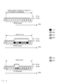
- Fig. 3 schematically shows exemplarily the usage of subframes zero to nine according to the prior art.
- the 14 OFDM symbols that build a normal unicast subframe as e.g. the subframes 1-4 and 6-9 in LTE, are depicted in the upper part of fig. 3 .
- the cell-specific reference signals CRS are transmitted in every subframe, and can be used for channel estimation for coherent demodulation of downlink transmission, and for cell-search measurements, both for neighbour-cell measurements for handover and for measurements before initial access.
- the OFDM symbols 0, 4, 7 and 11 are used for transmission of cell-specific reference signals CRS.
- minimum power-amplifier transmission-time fraction which is defined as the ratio between the time the base station is required to transmit signals, as e.g. cell-specific reference signals CRS, primary and secondary synchronization signals PSS and SSS, or broadcast channel information BCH, and the total time.
- the power profile of the power amplifier is depicted as a solid line just above the OFDM symbols.
- "PA on” in fig. 3 indicates, that the power amplifier is switched on
- "PA off” in fig. 3 indicates, that the power amplifier is switched off.
- the power amplifier needs to ramp up the power to the desired level somewhat before the transmission but can then be switched off fairly quickly.
- half an OFDM symbol must be added to each transmission to allow for the power amplifier to reach the desired power level from the power saving state.
- the addition of half an OFDM symbol is an example, and the time will depend on hardware characteristics.
- a normal unicast subframe according to the prior art as depicted in the upper part of fig. 3 contains cell-specific reference signals CRS in four OFDM symbols. This structure will result in four transmissions each being 1.5 OFDM symbols long, which can be seen by the upper solid line representing the power profile. Thus, the transmission structure results in a minimum power-amplifier transmission-time fraction of (6 OFDM symbols)/(14 OFDM symbols) ⁇ 43%.
- the 14 OFDM symbols that build subframe zero in LTE are depicted in the middle part of fig. 3 .
- the OFDM symbols 0, 4, 7 and 11 are used for transmission of cell-specific reference signals CRS.
- the primary synchronization signals PSS and the secondary synchronization signals SSS are transmitted in every frame in subframe 0 and 5, in which the OFDM symbols 5 and 6 are used for the primary synchronization signals PSS and the secondary synchronization signals SSS respectively.
- the primary synchronization signals PSS and the secondary synchronization signals SSS are used to assist the cell search.
- the broadcast channel information BCH is transmitted in the first subframe of each frame in four consecutive frames.
- the broadcast channel information is transmitted to all user terminals in the cell and includes relevant system parameters to enable the user terminals to establish a signalling connection with the base station or the radio access network.
- equivalent information is broadcasted within the frame control header (FCH), uplink and downlink maps and the uplink and downlink channel descriptor, UCD and DCD, respectively.
- the OFDM symbols 8, 9 and 10 are used for transmission of the broadcast channel information BCH in subframe zero.
- the broadcast channel information BCH includes, among other parameters, signaling of the system frame number (SFN), which is required to enable sending paging messages to a user terminal.
- SFN system frame number
- the transmission structure for subframe zero will result in two transmissions being 1.5 and 8.5 OFDM symbols long, respectively, which can be seen by the solid line representing the power profile.
- the transmission structure results in a minimum power-amplifier transmission-time fraction of (10 OFDM symbols)/(14 OFDM symbols) ⁇ 71%.
- the 14 OFDM symbols that build subframe five in LTE are depicted in the lower part of fig. 3 .
- the OFDM symbols 0, 4, 7 and 11 are used for transmission of cell-specific reference signals CRS.
- the primary synchronization signals PSS and the secondary synchronization signals SSS are transmitted in every frame in subframe 0 and 5, in which the OFDM symbols 5 and 6 are used for the primary synchronization signals PSS and the secondary synchronization signals SSS respectively.
- the transmission structure for subframe five will result in three transmissions being 1.5, 4.5 and 1.5 OFDM symbols long, respectively, which can be seen by the solid line representing the power profile.
- the transmission structure results in a minimum power-amplifier transmission-time fraction of (7.5 OFDM symbols)/(14 OFDM symbols) ⁇ 54%.
- cell-specific reference signals CRS are transmitted in all subframes predefined for transmission of downlink control signaling or downlink data, i.e. cell-specific reference signals CRS are transmitted in all predefined subframes regardless of the predefined subframes really being used for downlink control signaling or downlink data.
- Such downlink control signaling comprises in LTE the physical control format indicator channel (PCFICH), the physical downlink control channel (PDCCH) and the physical hybrid-ARQ indicator channel (PHICH).
- Downlink data is e.g. transmitted in the broadcast channel BCH, the physical downlink shared channel (PDSCH), or the physical multicast channel (PMCH).
- FIG. 3 An example for said mode for transmission is depicted in fig. 3 . It can be seen that in the unicast subframes cell-specific reference signals CRS are transmitted although no further downlink control signaling or downlink data is present.
- cell-specific reference signals are only transmitted in subframes which are really used to transmit downlink control signaling or downlink data.
- the 14 OFDM symbols that build a normal unicast subframe as e.g. the subframes 1-4 and 6-9 in LTE, are depicted in the upper part of fig. 4 .
- the cell-specific reference signals CRS are only transmitted in subframes which are really used to transmit downlink control signaling or downlink data.
- no OFDM symbols are used for transmission of cell-specific reference signals CRS, as no downlink control signaling or downlink data is transmitted.
- the 14 OFDM symbols that build subframe zero in LTE are depicted in the middle part of fig. 4 .
- cell-specific reference signals CRS are transmitted, as downlink control signaling is transmitted in the form of broadcast channel information BCH.
- the OFDM symbols 4, 7 and 11 are used for transmission of cell-specific reference signals CRS.
- the OFDM symbols 4, 7 and 11 are used for transmission of cell-specific reference signals CRS.
- the primary synchronization signals PSS and the secondary synchronization signals SSS, and the broadcast channel information BCH are transmitted in subframe 0 in the OFDM symbols 5, 6 and 8-10 respectively.
- the transmission structure for subframe zero will result in one transmission being 7.5 OFDM symbols long, which can be seen by the solid line representing the power profile.
- the transmission structure results in a minimum power-amplifier transmission-time fraction of (7.5 OFDM symbols)/(14 OFDM sym-bolts) ⁇ 54% compared to 71% in the transmission mode depicted in fig. 3 .
- the 14 OFDM symbols that build subframe five in LTE are depicted in the lower part of fig. 4 .
- no OFDM symbols are used for transmission of cell-specific reference signals CRS, as only primary synchronization signals PSS and secondary synchronization signals SSS are transmitted, but no downlink control signaling or downlink data is transmitted.
- the primary synchronization signals PSS and the secondary synchronization signals SSS are transmitted in the OFDM symbols 5 and 6 respectively.
- the transmission structure for subframe five will result in one transmission being 2.5 OFDM symbols long, which can be seen by the solid line representing the power profile.
- the transmission structure results in a minimum power-amplifier transmission-time fraction of (2.5 OFDM symbols)/(14 OFDM sym-bolts) ⁇ 18% compared to 54% in the transmission mode depicted in fig. 3 .
- the overall minimum power-amplifier transmission-time fraction of the mode for transmission between a base station BS and user terminals UE in which cell-specific reference signals are only transmitted in subframes which are used to transmit downlink control signaling or downlink data, is in average significantly below the overall minimum power-amplifier transmission-time fraction of the mode for transmission between a base station BS and user terminals UE, in which cell-specific reference signals are transmitted in all subframes predefined for transmission of downlink control signaling or downlink data.
- a dedicated mode for determination of at least one of the group of channel quality information, precoding matrix information, and rank information is chosen.
- a first mode for transmission between a base station BS and user terminals UE in which cell-specific reference signals are only transmitted in subframes which are used to transmit downlink control signaling or downlink data, there is only the guarantee that cell-specific reference signals are transmitted in subframe zero.
- the user terminals UE use a first mode for determination of at least one of the group of channel quality information, precoding matrix information, and rank information which is based on the cell-specific reference signals transmitted in the first subframe within the frames.
- the user terminals UE use a second mode for determination of at least one of the group of channel quality information, precoding matrix information, and rank information which is based on the cell-specific reference signals transmitted in all subframes predefined for transmission of downlink control signaling or downlink data.
- a user terminal receives less cell specific reference signals as compared to the second mode, the accuracy of the computed channel quality information, precoding matrix information, and rank information is negatively impacted.
- channel quality information In LTE, channel quality information, precoding matrix information, or rank information, are comprised in the so-called channel quality indicator, precoding matrix indicator, and rank indicator respectively.
- the channel quality indicator represents the recommended modulation scheme and coding rate that should, preferably, be used for the downlink transmission.
- the precoding matrix indicator provides a precoder matrix that should, preferably, be used for downlink transmission.
- the rank indicator provides information about the channel rank, i.e. the number of layers that should, preferably, be used for downlink transmission to a user terminal.
- LTE release 8 cell-specific reference signals are transmitted in each subframe over the full system bandwidth.
- some "blank" subframes may be predefined, e.g. on a semi-static basis by higher layer signaling to the user terminals, so as not to be used for transmission of downlink cell specific reference signals, downlink control signaling or downlink data.
- the cell-specific reference signals are used for following purposes:
- the first mode for determination of at least one of the group of channel quality information, precoding matrix information, and rank information is additionally based on the cell-specific reference signals transmitted in subframes which are used to transmit downlink control signaling or downlink data.
- measured radio parameters like e.g. CQI, PMI, or RI calculated based on the cell-specific reference signals are more accurate.
- the reporting rate of CQI/PMI/RI could be adapted when switching between the first and second mode, e.g. by configuring two different CQI/PMI/RI reporting configurations in the user terminal during radio link setup, where in the first mode the CQI/PMI/RI reporting rate is reduced compared to the CQI/PMI/RI reporting rate in the second mode.
- the switching to said first mode for transmission in which the sending of cell-specific reference signals is dynamically suspended is particularly useful for reduction of energy consumption in low-load scenarios, as in low-load scenarios, there is a higher probability of subframes without downlink control signaling or downlink data.
- the first mode for transmission between a base station BS and user terminals UE in which cell-specific reference signals are only transmitted in subframes which are used to transmit downlink control signaling or downlink data, is scheduled if the estimated usage of radio resources is below a predefined value
- the second mode for transmission between a base station BS and user terminals UE in which cell-specific reference signals are transmitted in all subframes predefined for transmission of downlink control signaling or downlink data, is scheduled if the estimated usage of radio resources is above a predefined value.
- the usage of radio resources can be estimated based on the amount of allocated downlink radio resources, based on the number of active user terminals UE served by the base station BS, or based on an aggregated data rate in downlink of the user terminals UE served by the base station BS.
- the use of said first mode for transmission or said second mode for transmission between a base station BS and user terminals UE is signaled by the base station BS to the user terminals UE preferably via a broadcast channel (BCH).
- BCH broadcast channel
- This signaling of the transmission mode to the user terminals has the advantage that the user terminals may reduce their energy consumption by switching off algorithms dedicated for the detection of the transmission mode.
- the user terminals UE detect in which subframes cell-specific reference signals are transmitted based on a power offset of cell-specific reference signals to primary synchronization signals or secondary synchronization signals, and deduce based on the subframes in which cell-specific reference signals are transmitted whether the first mode for transmission or the second mode for transmission is used.
- the user terminals UE detect the power of received signals, and can determine whether cell-specific reference signals are among the received signals, as the user terminals UE detect the power of primary synchronization signals or secondary synchronization signals and know the power offset of cell-specific reference signals to primary synchronization signals or secondary synchronization signals.
- the base station BS signals to the user terminals UE the power offset of cell-specific reference signals to primary synchronization signals or secondary synchronization signals.
- the power offset of cell-specific reference signals to primary synchronization signals or secondary synchronization signals can also be known in the user terminals UE in advance.
- the cell-specific reference signals are transmitted only in either-the first OFDM symbol of subframes, or the first and the fifth OFDM symbols of subframes.
Landscapes
- Engineering & Computer Science (AREA)
- Computer Networks & Wireless Communication (AREA)
- Signal Processing (AREA)
- Mobile Radio Communication Systems (AREA)
Priority Applications (1)
| Application Number | Priority Date | Filing Date | Title |
|---|---|---|---|
| EP10305150A EP2360977B1 (fr) | 2010-02-15 | 2010-02-15 | Procédé de transmission entre une station de base et des terminaux utilisateur et terminal utilisateur correspondant |
Applications Claiming Priority (1)
| Application Number | Priority Date | Filing Date | Title |
|---|---|---|---|
| EP10305150A EP2360977B1 (fr) | 2010-02-15 | 2010-02-15 | Procédé de transmission entre une station de base et des terminaux utilisateur et terminal utilisateur correspondant |
Publications (2)
| Publication Number | Publication Date |
|---|---|
| EP2360977A1 true EP2360977A1 (fr) | 2011-08-24 |
| EP2360977B1 EP2360977B1 (fr) | 2012-11-21 |
Family
ID=42246170
Family Applications (1)
| Application Number | Title | Priority Date | Filing Date |
|---|---|---|---|
| EP10305150A Not-in-force EP2360977B1 (fr) | 2010-02-15 | 2010-02-15 | Procédé de transmission entre une station de base et des terminaux utilisateur et terminal utilisateur correspondant |
Country Status (1)
| Country | Link |
|---|---|
| EP (1) | EP2360977B1 (fr) |
Cited By (1)
| Publication number | Priority date | Publication date | Assignee | Title |
|---|---|---|---|---|
| US20140198749A1 (en) * | 2013-01-14 | 2014-07-17 | Qualcomm Incorporated | Transmission and processing of higher order modulation |
Citations (5)
| Publication number | Priority date | Publication date | Assignee | Title |
|---|---|---|---|---|
| WO2009041871A1 (fr) * | 2007-09-28 | 2009-04-02 | Telefonaktiebolaget Lm Ericsson (Publ) | Procédé et dispositif de réduction d'énergie dans un système lte |
| EP2056628A1 (fr) * | 2007-10-30 | 2009-05-06 | Nokia Siemens Networks Oy | Élément de réseau de communications et procédé pour commuter les états d'activité |
| JP2009182801A (ja) * | 2008-01-31 | 2009-08-13 | Toshiba Corp | 無線送信機 |
| WO2009140988A1 (fr) * | 2008-05-23 | 2009-11-26 | Nokia Siemens Networks Oy | Réactivation d’une station de base en mode d’attente |
| US20100002614A1 (en) * | 2008-07-02 | 2010-01-07 | Qualcomm Incorporated | Low power modes for femto cells |
-
2010
- 2010-02-15 EP EP10305150A patent/EP2360977B1/fr not_active Not-in-force
Patent Citations (5)
| Publication number | Priority date | Publication date | Assignee | Title |
|---|---|---|---|---|
| WO2009041871A1 (fr) * | 2007-09-28 | 2009-04-02 | Telefonaktiebolaget Lm Ericsson (Publ) | Procédé et dispositif de réduction d'énergie dans un système lte |
| EP2056628A1 (fr) * | 2007-10-30 | 2009-05-06 | Nokia Siemens Networks Oy | Élément de réseau de communications et procédé pour commuter les états d'activité |
| JP2009182801A (ja) * | 2008-01-31 | 2009-08-13 | Toshiba Corp | 無線送信機 |
| WO2009140988A1 (fr) * | 2008-05-23 | 2009-11-26 | Nokia Siemens Networks Oy | Réactivation d’une station de base en mode d’attente |
| US20100002614A1 (en) * | 2008-07-02 | 2010-01-07 | Qualcomm Incorporated | Low power modes for femto cells |
Non-Patent Citations (2)
| Title |
|---|
| ERICSSON ET AL: "Extended cell DTX for enhanced energy-efficient network operation", 3GPP DRAFT; R1-095011{ENERGY EFFICIENCY}, 3RD GENERATION PARTNERSHIP PROJECT (3GPP), MOBILE COMPETENCE CENTRE ; 650, ROUTE DES LUCIOLES ; F-06921 SOPHIA-ANTIPOLIS CEDEX ; FRANCE, no. Jeju; 20091109, 9 November 2009 (2009-11-09), XP050389361 * |
| HUAWEI: "Opportunities for Energy Savings in LTE Networks", 3GPP TSG RAN WG1 MEETING 59BIS; R1-100275, 18 January 2010 (2010-01-18) - 22 January 2010 (2010-01-22), Valencia, Spain, pages 1 - 4, XP002588640 * |
Cited By (5)
| Publication number | Priority date | Publication date | Assignee | Title |
|---|---|---|---|---|
| US20140198749A1 (en) * | 2013-01-14 | 2014-07-17 | Qualcomm Incorporated | Transmission and processing of higher order modulation |
| WO2014110515A1 (fr) * | 2013-01-14 | 2014-07-17 | Qualcomm Incorporated | Transmission et traitement de modulation d'ordre supérieur |
| JP2016510539A (ja) * | 2013-01-14 | 2016-04-07 | クゥアルコム・インコーポレイテッドQualcomm Incorporated | 高次変調の送信および処理 |
| KR101739001B1 (ko) | 2013-01-14 | 2017-06-08 | 퀄컴 인코포레이티드 | 더 높은 차수의 변조의 송신 및 프로세싱 |
| US10432370B2 (en) * | 2013-01-14 | 2019-10-01 | Qualcomm Incorporated | Transmission and processing of higher order modulation |
Also Published As
| Publication number | Publication date |
|---|---|
| EP2360977B1 (fr) | 2012-11-21 |
Similar Documents
| Publication | Publication Date | Title |
|---|---|---|
| US10721727B2 (en) | DRX for narrowband transmissions | |
| JP5759067B2 (ja) | 基準信号の伝送方法、そのための基地局およびユーザ端末 | |
| TW202015456A (zh) | 用於支援用於功率節省的多種功率和頻譜高效模式的方法和裝置 | |
| US9300377B2 (en) | Method for downlink communication by means of a downlink superimposed radio signal, a base station and a user terminal therefor | |
| US20120002635A1 (en) | Method and apparatus for supporting carrier aggregation | |
| KR20120096408A (ko) | 무선 통신 시스템에서 단말의 상향링크 송신 전력 제어 방법 및 이를 위한 장치 | |
| KR102059983B1 (ko) | Pucch를 통한 고도 pmi 보고 | |
| JP7639075B2 (ja) | 通信システム、基地局および通信端末 | |
| KR20120056869A (ko) | 기지국과 이용자 단말들 사이의 송신들을 스케줄링하기 위한 방법, 기지국 및 그를 위한 통신 네트워크 | |
| WO2013055178A2 (fr) | Procédé d'émission/réception d'un signal par un terminal dans un système de communication sans fil et appareil associé | |
| US20160056868A1 (en) | Base station and communication control method | |
| JP2016516335A (ja) | 無線通信システムにおいて基地局が端末に制御チャネルを送信する方法及びそのための装置 | |
| US11096067B2 (en) | Method for coordination of transmission from base stations, and a base station therefor | |
| EP2360976A1 (fr) | Procédé de programmation d'un mode de transmission, station de base et terminal utilisateur correspondant | |
| EP4661514A1 (fr) | Procédé et dispositif utilisés pour une communication sans fil | |
| EP2360977B1 (fr) | Procédé de transmission entre une station de base et des terminaux utilisateur et terminal utilisateur correspondant | |
| EP2333983B1 (fr) | Procédé pour la communication en liaison descendante au moyen d'un signal radio superposé en liaison descendante, station de base et terminal utilisateur correspondant | |
| EP2542005B1 (fr) | Procédé pour les affectations de signalisation de sous-trames, station de base et terminal utilisateur correspondant | |
| EP4665041A1 (fr) | Procédé et appareil de communication sans fil | |
| EP2701438B1 (fr) | Procédé pour la coordination de la transmission à partir de stations de base et dispositifs de réseau correspondants | |
| EP2884795B1 (fr) | Procédé de communication sans fil utilisant des sous-trames presque vides et réseau de communication |
Legal Events
| Date | Code | Title | Description |
|---|---|---|---|
| PUAI | Public reference made under article 153(3) epc to a published international application that has entered the european phase |
Free format text: ORIGINAL CODE: 0009012 |
|
| PUAI | Public reference made under article 153(3) epc to a published international application that has entered the european phase |
Free format text: ORIGINAL CODE: 0009012 |
|
| AK | Designated contracting states |
Kind code of ref document: A1 Designated state(s): AT BE BG CH CY CZ DE DK EE ES FI FR GB GR HR HU IE IS IT LI LT LU LV MC MK MT NL NO PL PT RO SE SI SK SM TR |
|
| AX | Request for extension of the european patent |
Extension state: AL BA RS |
|
| RAP1 | Party data changed (applicant data changed or rights of an application transferred) |
Owner name: ALCATEL LUCENT |
|
| 17P | Request for examination filed |
Effective date: 20120224 |
|
| GRAP | Despatch of communication of intention to grant a patent |
Free format text: ORIGINAL CODE: EPIDOSNIGR1 |
|
| GRAS | Grant fee paid |
Free format text: ORIGINAL CODE: EPIDOSNIGR3 |
|
| GRAA | (expected) grant |
Free format text: ORIGINAL CODE: 0009210 |
|
| AK | Designated contracting states |
Kind code of ref document: B1 Designated state(s): AT BE BG CH CY CZ DE DK EE ES FI FR GB GR HR HU IE IS IT LI LT LU LV MC MK MT NL NO PL PT RO SE SI SK SM TR |
|
| REG | Reference to a national code |
Ref country code: GB Ref legal event code: FG4D |
|
| REG | Reference to a national code |
Ref country code: CH Ref legal event code: EP |
|
| REG | Reference to a national code |
Ref country code: AT Ref legal event code: REF Ref document number: 585612 Country of ref document: AT Kind code of ref document: T Effective date: 20121215 |
|
| REG | Reference to a national code |
Ref country code: IE Ref legal event code: FG4D |
|
| REG | Reference to a national code |
Ref country code: DE Ref legal event code: R096 Ref document number: 602010003726 Country of ref document: DE Effective date: 20130117 |
|
| REG | Reference to a national code |
Ref country code: NL Ref legal event code: VDEP Effective date: 20121121 |
|
| REG | Reference to a national code |
Ref country code: AT Ref legal event code: MK05 Ref document number: 585612 Country of ref document: AT Kind code of ref document: T Effective date: 20121121 |
|
| REG | Reference to a national code |
Ref country code: LT Ref legal event code: MG4D |
|
| PG25 | Lapsed in a contracting state [announced via postgrant information from national office to epo] |
Ref country code: LT Free format text: LAPSE BECAUSE OF FAILURE TO SUBMIT A TRANSLATION OF THE DESCRIPTION OR TO PAY THE FEE WITHIN THE PRESCRIBED TIME-LIMIT Effective date: 20121121 Ref country code: FI Free format text: LAPSE BECAUSE OF FAILURE TO SUBMIT A TRANSLATION OF THE DESCRIPTION OR TO PAY THE FEE WITHIN THE PRESCRIBED TIME-LIMIT Effective date: 20121121 Ref country code: ES Free format text: LAPSE BECAUSE OF FAILURE TO SUBMIT A TRANSLATION OF THE DESCRIPTION OR TO PAY THE FEE WITHIN THE PRESCRIBED TIME-LIMIT Effective date: 20130304 Ref country code: NO Free format text: LAPSE BECAUSE OF FAILURE TO SUBMIT A TRANSLATION OF THE DESCRIPTION OR TO PAY THE FEE WITHIN THE PRESCRIBED TIME-LIMIT Effective date: 20130221 Ref country code: SE Free format text: LAPSE BECAUSE OF FAILURE TO SUBMIT A TRANSLATION OF THE DESCRIPTION OR TO PAY THE FEE WITHIN THE PRESCRIBED TIME-LIMIT Effective date: 20121121 |
|
| PG25 | Lapsed in a contracting state [announced via postgrant information from national office to epo] |
Ref country code: LV Free format text: LAPSE BECAUSE OF FAILURE TO SUBMIT A TRANSLATION OF THE DESCRIPTION OR TO PAY THE FEE WITHIN THE PRESCRIBED TIME-LIMIT Effective date: 20121121 Ref country code: PT Free format text: LAPSE BECAUSE OF FAILURE TO SUBMIT A TRANSLATION OF THE DESCRIPTION OR TO PAY THE FEE WITHIN THE PRESCRIBED TIME-LIMIT Effective date: 20130321 Ref country code: SI Free format text: LAPSE BECAUSE OF FAILURE TO SUBMIT A TRANSLATION OF THE DESCRIPTION OR TO PAY THE FEE WITHIN THE PRESCRIBED TIME-LIMIT Effective date: 20121121 Ref country code: PL Free format text: LAPSE BECAUSE OF FAILURE TO SUBMIT A TRANSLATION OF THE DESCRIPTION OR TO PAY THE FEE WITHIN THE PRESCRIBED TIME-LIMIT Effective date: 20121121 Ref country code: GR Free format text: LAPSE BECAUSE OF FAILURE TO SUBMIT A TRANSLATION OF THE DESCRIPTION OR TO PAY THE FEE WITHIN THE PRESCRIBED TIME-LIMIT Effective date: 20130222 Ref country code: BE Free format text: LAPSE BECAUSE OF FAILURE TO SUBMIT A TRANSLATION OF THE DESCRIPTION OR TO PAY THE FEE WITHIN THE PRESCRIBED TIME-LIMIT Effective date: 20121121 |
|
| PG25 | Lapsed in a contracting state [announced via postgrant information from national office to epo] |
Ref country code: AT Free format text: LAPSE BECAUSE OF FAILURE TO SUBMIT A TRANSLATION OF THE DESCRIPTION OR TO PAY THE FEE WITHIN THE PRESCRIBED TIME-LIMIT Effective date: 20121121 |
|
| PG25 | Lapsed in a contracting state [announced via postgrant information from national office to epo] |
Ref country code: CZ Free format text: LAPSE BECAUSE OF FAILURE TO SUBMIT A TRANSLATION OF THE DESCRIPTION OR TO PAY THE FEE WITHIN THE PRESCRIBED TIME-LIMIT Effective date: 20121121 Ref country code: BG Free format text: LAPSE BECAUSE OF FAILURE TO SUBMIT A TRANSLATION OF THE DESCRIPTION OR TO PAY THE FEE WITHIN THE PRESCRIBED TIME-LIMIT Effective date: 20130221 Ref country code: SK Free format text: LAPSE BECAUSE OF FAILURE TO SUBMIT A TRANSLATION OF THE DESCRIPTION OR TO PAY THE FEE WITHIN THE PRESCRIBED TIME-LIMIT Effective date: 20121121 Ref country code: EE Free format text: LAPSE BECAUSE OF FAILURE TO SUBMIT A TRANSLATION OF THE DESCRIPTION OR TO PAY THE FEE WITHIN THE PRESCRIBED TIME-LIMIT Effective date: 20121121 Ref country code: DK Free format text: LAPSE BECAUSE OF FAILURE TO SUBMIT A TRANSLATION OF THE DESCRIPTION OR TO PAY THE FEE WITHIN THE PRESCRIBED TIME-LIMIT Effective date: 20121121 |
|
| PG25 | Lapsed in a contracting state [announced via postgrant information from national office to epo] |
Ref country code: IT Free format text: LAPSE BECAUSE OF FAILURE TO SUBMIT A TRANSLATION OF THE DESCRIPTION OR TO PAY THE FEE WITHIN THE PRESCRIBED TIME-LIMIT Effective date: 20121121 Ref country code: RO Free format text: LAPSE BECAUSE OF FAILURE TO SUBMIT A TRANSLATION OF THE DESCRIPTION OR TO PAY THE FEE WITHIN THE PRESCRIBED TIME-LIMIT Effective date: 20121121 Ref country code: NL Free format text: LAPSE BECAUSE OF FAILURE TO SUBMIT A TRANSLATION OF THE DESCRIPTION OR TO PAY THE FEE WITHIN THE PRESCRIBED TIME-LIMIT Effective date: 20121121 |
|
| PLBE | No opposition filed within time limit |
Free format text: ORIGINAL CODE: 0009261 |
|
| STAA | Information on the status of an ep patent application or granted ep patent |
Free format text: STATUS: NO OPPOSITION FILED WITHIN TIME LIMIT |
|
| PG25 | Lapsed in a contracting state [announced via postgrant information from national office to epo] |
Ref country code: MC Free format text: LAPSE BECAUSE OF NON-PAYMENT OF DUE FEES Effective date: 20130228 |
|
| 26N | No opposition filed |
Effective date: 20130822 |
|
| REG | Reference to a national code |
Ref country code: FR Ref legal event code: GC Effective date: 20131018 |
|
| REG | Reference to a national code |
Ref country code: IE Ref legal event code: MM4A |
|
| REG | Reference to a national code |
Ref country code: DE Ref legal event code: R097 Ref document number: 602010003726 Country of ref document: DE Effective date: 20130822 |
|
| PG25 | Lapsed in a contracting state [announced via postgrant information from national office to epo] |
Ref country code: IE Free format text: LAPSE BECAUSE OF NON-PAYMENT OF DUE FEES Effective date: 20130215 Ref country code: HR Free format text: LAPSE BECAUSE OF FAILURE TO SUBMIT A TRANSLATION OF THE DESCRIPTION OR TO PAY THE FEE WITHIN THE PRESCRIBED TIME-LIMIT Effective date: 20130731 |
|
| PG25 | Lapsed in a contracting state [announced via postgrant information from national office to epo] |
Ref country code: MT Free format text: LAPSE BECAUSE OF FAILURE TO SUBMIT A TRANSLATION OF THE DESCRIPTION OR TO PAY THE FEE WITHIN THE PRESCRIBED TIME-LIMIT Effective date: 20121121 |
|
| REG | Reference to a national code |
Ref country code: CH Ref legal event code: PCOW Free format text: NEW ADDRESS: 148/152 ROUTE DE LA REINE, 92100 BOULOGNE-BILLANCOURT (FR) |
|
| REG | Reference to a national code |
Ref country code: CH Ref legal event code: PL |
|
| PG25 | Lapsed in a contracting state [announced via postgrant information from national office to epo] |
Ref country code: CH Free format text: LAPSE BECAUSE OF NON-PAYMENT OF DUE FEES Effective date: 20140228 Ref country code: LI Free format text: LAPSE BECAUSE OF NON-PAYMENT OF DUE FEES Effective date: 20140228 |
|
| REG | Reference to a national code |
Ref country code: FR Ref legal event code: RG Effective date: 20141016 |
|
| REG | Reference to a national code |
Ref country code: FR Ref legal event code: PLFP Year of fee payment: 6 |
|
| PG25 | Lapsed in a contracting state [announced via postgrant information from national office to epo] |
Ref country code: SM Free format text: LAPSE BECAUSE OF FAILURE TO SUBMIT A TRANSLATION OF THE DESCRIPTION OR TO PAY THE FEE WITHIN THE PRESCRIBED TIME-LIMIT Effective date: 20121121 |
|
| PG25 | Lapsed in a contracting state [announced via postgrant information from national office to epo] |
Ref country code: CY Free format text: LAPSE BECAUSE OF FAILURE TO SUBMIT A TRANSLATION OF THE DESCRIPTION OR TO PAY THE FEE WITHIN THE PRESCRIBED TIME-LIMIT Effective date: 20121121 Ref country code: TR Free format text: LAPSE BECAUSE OF FAILURE TO SUBMIT A TRANSLATION OF THE DESCRIPTION OR TO PAY THE FEE WITHIN THE PRESCRIBED TIME-LIMIT Effective date: 20121121 |
|
| PG25 | Lapsed in a contracting state [announced via postgrant information from national office to epo] |
Ref country code: MK Free format text: LAPSE BECAUSE OF FAILURE TO SUBMIT A TRANSLATION OF THE DESCRIPTION OR TO PAY THE FEE WITHIN THE PRESCRIBED TIME-LIMIT Effective date: 20121121 Ref country code: LU Free format text: LAPSE BECAUSE OF NON-PAYMENT OF DUE FEES Effective date: 20130215 Ref country code: HU Free format text: LAPSE BECAUSE OF FAILURE TO SUBMIT A TRANSLATION OF THE DESCRIPTION OR TO PAY THE FEE WITHIN THE PRESCRIBED TIME-LIMIT; INVALID AB INITIO Effective date: 20100215 |
|
| REG | Reference to a national code |
Ref country code: FR Ref legal event code: PLFP Year of fee payment: 7 |
|
| PGFP | Annual fee paid to national office [announced via postgrant information from national office to epo] |
Ref country code: DE Payment date: 20160218 Year of fee payment: 7 |
|
| PGFP | Annual fee paid to national office [announced via postgrant information from national office to epo] |
Ref country code: FR Payment date: 20160218 Year of fee payment: 7 Ref country code: GB Payment date: 20160217 Year of fee payment: 7 |
|
| PG25 | Lapsed in a contracting state [announced via postgrant information from national office to epo] |
Ref country code: IS Free format text: LAPSE BECAUSE OF FAILURE TO SUBMIT A TRANSLATION OF THE DESCRIPTION OR TO PAY THE FEE WITHIN THE PRESCRIBED TIME-LIMIT Effective date: 20121121 |
|
| REG | Reference to a national code |
Ref country code: DE Ref legal event code: R119 Ref document number: 602010003726 Country of ref document: DE |
|
| GBPC | Gb: european patent ceased through non-payment of renewal fee |
Effective date: 20170215 |
|
| REG | Reference to a national code |
Ref country code: FR Ref legal event code: ST Effective date: 20171031 |
|
| PG25 | Lapsed in a contracting state [announced via postgrant information from national office to epo] |
Ref country code: DE Free format text: LAPSE BECAUSE OF NON-PAYMENT OF DUE FEES Effective date: 20170901 Ref country code: FR Free format text: LAPSE BECAUSE OF NON-PAYMENT OF DUE FEES Effective date: 20170228 |
|
| PG25 | Lapsed in a contracting state [announced via postgrant information from national office to epo] |
Ref country code: GB Free format text: LAPSE BECAUSE OF NON-PAYMENT OF DUE FEES Effective date: 20170215 |