EP2361162B1 - Vorrichtung zum verlangsamen und vorübergehenden speichern von warmgewalzten produkten - Google Patents
Vorrichtung zum verlangsamen und vorübergehenden speichern von warmgewalzten produkten Download PDFInfo
- Publication number
- EP2361162B1 EP2361162B1 EP09736743A EP09736743A EP2361162B1 EP 2361162 B1 EP2361162 B1 EP 2361162B1 EP 09736743 A EP09736743 A EP 09736743A EP 09736743 A EP09736743 A EP 09736743A EP 2361162 B1 EP2361162 B1 EP 2361162B1
- Authority
- EP
- European Patent Office
- Prior art keywords
- drum
- axis
- rollers
- product
- velocity
- Prior art date
- Legal status (The legal status is an assumption and is not a legal conclusion. Google has not performed a legal analysis and makes no representation as to the accuracy of the status listed.)
- Not-in-force
Links
Images





Classifications
-
- B—PERFORMING OPERATIONS; TRANSPORTING
- B21—MECHANICAL METAL-WORKING WITHOUT ESSENTIALLY REMOVING MATERIAL; PUNCHING METAL
- B21C—MANUFACTURE OF METAL SHEETS, WIRE, RODS, TUBES, PROFILES OR LIKE SEMI-MANUFACTURED PRODUCTS OTHERWISE THAN BY ROLLING; AUXILIARY OPERATIONS USED IN CONNECTION WITH METAL-WORKING WITHOUT ESSENTIALLY REMOVING MATERIAL
- B21C47/00—Winding-up, coiling or winding-off metal wire, metal band or other flexible metal material characterised by features relevant to metal processing only
- B21C47/02—Winding-up or coiling
- B21C47/10—Winding-up or coiling by means of a moving guide
- B21C47/14—Winding-up or coiling by means of a moving guide by means of a rotating guide, e.g. laying the material around a stationary reel or drum
-
- B—PERFORMING OPERATIONS; TRANSPORTING
- B21—MECHANICAL METAL-WORKING WITHOUT ESSENTIALLY REMOVING MATERIAL; PUNCHING METAL
- B21C—MANUFACTURE OF METAL SHEETS, WIRE, RODS, TUBES, PROFILES OR LIKE SEMI-MANUFACTURED PRODUCTS OTHERWISE THAN BY ROLLING; AUXILIARY OPERATIONS USED IN CONNECTION WITH METAL-WORKING WITHOUT ESSENTIALLY REMOVING MATERIAL
- B21C49/00—Devices for temporarily accumulating material
-
- B—PERFORMING OPERATIONS; TRANSPORTING
- B21—MECHANICAL METAL-WORKING WITHOUT ESSENTIALLY REMOVING MATERIAL; PUNCHING METAL
- B21C—MANUFACTURE OF METAL SHEETS, WIRE, RODS, TUBES, PROFILES OR LIKE SEMI-MANUFACTURED PRODUCTS OTHERWISE THAN BY ROLLING; AUXILIARY OPERATIONS USED IN CONNECTION WITH METAL-WORKING WITHOUT ESSENTIALLY REMOVING MATERIAL
- B21C47/00—Winding-up, coiling or winding-off metal wire, metal band or other flexible metal material characterised by features relevant to metal processing only
- B21C47/02—Winding-up or coiling
- B21C47/10—Winding-up or coiling by means of a moving guide
- B21C47/14—Winding-up or coiling by means of a moving guide by means of a rotating guide, e.g. laying the material around a stationary reel or drum
- B21C47/143—Winding-up or coiling by means of a moving guide by means of a rotating guide, e.g. laying the material around a stationary reel or drum the guide being a tube
-
- B—PERFORMING OPERATIONS; TRANSPORTING
- B21—MECHANICAL METAL-WORKING WITHOUT ESSENTIALLY REMOVING MATERIAL; PUNCHING METAL
- B21B—ROLLING OF METAL
- B21B41/00—Guiding, conveying, or accumulating easily-flexible work, e.g. wire, sheet metal bands, in loops or curves; Loop lifters
Definitions
- This invention relates to accumulators employed in rolling mills to temporarily accumulate and decelerate hot rolled products. Examples of such accumulators are described in U.S. Patent Nos. 7, 021, 103 and 7, 093, 472 .
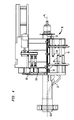
- a curved guide 12 has an entry end 12a aligned with a first axis A 1 to receive a hot rolled product traveling at a first velocity V 1 .
- the guide has an exit end 12b spaced radially from axis A 1 and orientated to deliver the product in an exit direction along a second axis A 2 transverse to axis A 1 .
- the guide 12 is rotatable about axis A 1 in a direction opposite to the exit direction of the product and at a speed at which its exit end 12b has a second velocity V 2 lower than velocity V 1 .
- the product is thus delivered from the exit end 12b as a helical formation of rings R at a third velocity V 3 equal to V 1 -V 2 .
- a cylindrical drum 14 is arranged to axially receive the rings R.
- the drum is rotatable about axis A 1 in a direction opposite to the direction of rotation of guide 12 and at a speed such that the product is unwound from the drum at velocity V 3 .
- a receiving means in the form of a catcher 16 receives the product being unwound from the drum and serves to direct the product to other equipment (not shown) for further processing.
- the catcher is movable in opposite directions along a path parallel to axis A 1 in order to maintain its alignment with the product being unwound from the drum.
- the mill control system will maintain a balanced relationship between the rotational velocity V 2 of the delivery end 12b of the curved guide and the incoming velocity V 1 of the product, with the objective being to provide the accumulating rings R with inner diameters only slightly larger than the diameter of the drum surface. This in turn will minimize frictional resistance to the gradual shifting of the rings along the drum surface in the direction of axis A 1 , while also maintaining a stable helical ring pattern on the drum.
- velocity V 1 may undergo sudden and random variations due to unsteady rolling conditions in the mill. If the mill control system is incapable of reacting to such variations with sufficient speed, the diameters of the rings may either increase or decrease to an undesirable extent. If the rings become too small, resulting in the product being tightly wound on the drum, the resulting frictional resistance will impede shifting of the rings along the drum surface. On the other hand, if the rings become too large, the helical ring pattern may be upset, leading to difficulties in unwinding the product from the drum.
- the objective of the present invention is to provide means for dealing with both of these potential problems.
- a shroud is configured to partially encircle the drum.
- Rotatable interior rollers are circumferentially spaced around the interior of the shroud.
- the interior rollers are spaced radially from the drum surface and extend in parallel relationship with the drum axis.
- a circumferential gap in the shroud serves to accommodate reciprocal movement of the catcher in a direction parallel to the drum axis.
- the interior rollers are staggered in the direction of the drum axis, with overlapping ends.
- rotatable exterior rollers are circumferentially spaced around the surface of the drum.
- the exterior rollers also extend in parallel relationship with the drum axis, and preferably are staggered in the direction of the drum axis with overlapping ends.
- the shroud and its interior rollers serve to radially confine the rings in the event that their diameters become too large, whereas the exterior rollers on the drum surface serve to radially support the rings in the event that they become too small and tightly wound on the drum.
- a means is provided for urging and controlling the ordered shifting of the helical formation of rings along the surface of the drum.
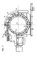
- a stationary shroud 18 partially encircles the drum 14, leaving a circumferential gap between the locations designated at "X" and "Y".
- the shroud carries a plurality of rotatable interior rollers indicated typically at 20.
- the rollers 20 are spaced radially from the drum surface and extend in parallel relationship to the drum axis A 1 .
- the rollers 20 are preferably staggered in the direction of axis A 1 , with overlapping ends.
- the gap between locations X and Y provides an unobstructed path for the movement, to and fro, of the catcher 16 during unwinding of the product from the drum.
- a plurality of exterior rollers 22 are spaced around the surface of the drum 14.
- the rollers 22 also are staggered in the direction of the drum axis, with overlapping ends.
- the interior rollers 20 on the shroud 18 will provide radial confinement to thereby preserve the helical ring formation.
- the exterior rollers 22 will serve to minimize frictional resistance to the shifting of the rings along the drum surface in the direction of axis A 1 .
- the apparatus may optionally include a means for urging and controlling the ordered shifting of the helical formation of rings R along the surface of the drum 14.
- one such means comprises a screw 24 spaced radially from the top of the drum surface and extending in a direction parallel to axis A 1 .
- the screw is carried by the shroud 18 and driven by a small gear motor 26.
- the individual rings R are received between the spiral threads of the screw and are thus propelled along the drum surface in an ordered spacing.
- a plurality of free wheeling pinch rollers indicated typically at 28 may be aligned along the top of the drum 14 in a direction parallel to axis A 1 .
- the rollers 28 are arranged to pinch an upper region of the helical ring formation against the drum surface.
Landscapes
- Engineering & Computer Science (AREA)
- Mechanical Engineering (AREA)
- Winding, Rewinding, Material Storage Devices (AREA)
Claims (11)
- Vorrichtung zum Verlangsamen und vorübergehenden Speichern eines warmgewalzten Produkts, das sich in Längsrichtung entlang einer ersten Achse (A1) mit einer ersten Geschwindigkeit V1 bewegt, wobei die besagte Vorrichtung umfasst:eine gekrümmte Führung (12), die ein Eintrittsende (12a) aufweist, das mit der besagten ersten Achse fluchtet, um das besagte Produkt aufzunehmen, und ein Austrittsende (12b) aufweist, das von der besagten ersten Achse radial beabstandet ist und dafür ausgerichtet ist, das besagte Produkt in einer Austrittsrichtung quer zu der besagten ersten Achse auszugeben, wobei die besagte gekrümmte Führung um die besagte erste Achse in einer Richtung, die zu der besagten Austrittsrichtung entgegengesetzt ist, und mit einer Geschwindigkeit, bei welcher das besagte Austrittsende eine zweite Geschwindigkeit V2 aufweist, die niedriger als V1 ist, drehbar ist, und derart, dass das besagte Produkt aus dem besagten Austrittsende als ein schraubenlinienförmiges Gebilde von Ringen und mit einer dritten Geschwindigkeit V3, die gleich V1-V2 ist, ausgegeben wird;eine zylindrische Trommel (14), die dafür eingerichtet ist, das besagte schraubenlinienförmige Gebilde von Ringen axial aufzunehmen, wobei die besagte Trommel um die besagte erste Achse in einer Richtung, die zu der Drehrichtung der besagten gekrümmten Führung entgegengesetzt ist, und mit einer solchen Geschwindigkeit, dass das besagte Produkt von der besagten Trommel mit der besagten dritten Geschwindigkeit abgewickelt wird, drehbar ist;Aufnahmemittel (16), die entlang eines zu der besagten ersten Achse parallelen Weges bewegbar sind, zum Aufnehmen des Produktes, das von der besagten Trommel abgewickelt wird; dadurch gekennzeichnet, dass die Vorrichtung ferner umfasst:eine Ummantelung (18), die dafür ausgebildet ist, die besagte Trommel teilweise zu umschließen; unddrehbare innere Walzen (20), die um das Innere der besagten Ummantelung herum in Umfangsrichtung beabstandet sind, wobei die besagten inneren Walzen radial von der Oberfläche der besagten Trommel beabstandet sind und sich parallel zu der besagten ersten Achse erstrecken.
- Vorrichtung nach Anspruch 1, welche ferner drehbare äußere Walzen (22) umfasst, die um die Oberfläche der besagten Trommel herum in Umfangsrichtung beabstandet sind, wobei sich die besagten äußeren Walzen ebenfalls parallel zu der besagten ersten Achse erstrecken.
- Vorrichtung nach Anspruch 1, wobei die besagten inneren Walzen in der Richtung der besagten ersten Achse zueinander versetzt sind, mit sich überlappenden Enden.
- Vorrichtung nach Anspruch 2, wobei die besagten äußeren Walzen in der Richtung der besagten ersten Achse zueinander versetzt sind, mit sich überlappenden Enden.
- Vorrichtung nach einem der Ansprüche 1-4, wobei die besagte Ummantelung außerhalb des Weges der besagten Aufnahmemittel angeordnet ist.
- Vorrichtung nach Anspruch 2 oder 4, wobei die besagten äußeren Walzen um den gesamten Umfang der besagten Trommel herum angeordnet sind.
- Vorrichtung nach Anspruch 1, wobei die besagten inneren Walzen dafür eingerichtet sind, die auf der besagten Trommel aufgenommene Spirale radial zu begrenzen.
- Vorrichtung nach Anspruch 2, wobei die besagten äußeren Walzen dafür eingerichtet sind, die auf der besagten Trommel aufgenommene Spirale radial abzustützen.
- Vorrichtung nach Anspruch 1 oder 2, welche ferner Mittel (24, 26, 28) zum Erzwingen und Steuern der geordneten Verschiebung des besagten schraubenförmigen Gebildes von Ringen entlang der Oberfläche der besagten Trommel umfasst.
- Vorrichtung nach Anspruch 9, wobei die besagten Mittel zum Erzwingen und Steuern eine rotierende Schnecke (24) umfassen, die von der Trommeloberfläche radial beabstandet ist und sich in einer zu der besagten ersten Achse parallelen Richtung erstreckt.
- Vorrichtung nach Anspruch 9, wobei die besagten Mittel zum Erzwingen und Steuern eine Vielzahl von Walzen (28) umfassen, die dafür eingerichtet sind, einen oberen Bereich des besagten schraubenlinienförmigen Ringgebildes gegen die Oberfläche der besagten Trommel zu klemmen.
Priority Applications (1)
| Application Number | Priority Date | Filing Date | Title |
|---|---|---|---|
| PL09736743T PL2361162T3 (pl) | 2008-11-17 | 2009-10-02 | Urządzenie do spowalniania i chwilowego gromadzenia wyrobu walcowanego na gorąco |
Applications Claiming Priority (2)
| Application Number | Priority Date | Filing Date | Title |
|---|---|---|---|
| US12/272,007 US8024949B2 (en) | 2008-11-17 | 2008-11-17 | Apparatus for decelerating and temporarily accumulating hot rolled product |
| PCT/US2009/059323 WO2010056430A1 (en) | 2008-11-17 | 2009-10-02 | Apparatus for decelerating and temporarily accumulating hot rolled product |
Publications (2)
| Publication Number | Publication Date |
|---|---|
| EP2361162A1 EP2361162A1 (de) | 2011-08-31 |
| EP2361162B1 true EP2361162B1 (de) | 2012-11-28 |
Family
ID=41566108
Family Applications (1)
| Application Number | Title | Priority Date | Filing Date |
|---|---|---|---|
| EP09736743A Not-in-force EP2361162B1 (de) | 2008-11-17 | 2009-10-02 | Vorrichtung zum verlangsamen und vorübergehenden speichern von warmgewalzten produkten |
Country Status (12)
| Country | Link |
|---|---|
| US (1) | US8024949B2 (de) |
| EP (1) | EP2361162B1 (de) |
| JP (1) | JP2012509179A (de) |
| KR (1) | KR20110089138A (de) |
| CN (1) | CN102239017A (de) |
| BR (1) | BRPI0921256A2 (de) |
| CA (1) | CA2743886A1 (de) |
| ES (1) | ES2400504T3 (de) |
| MX (1) | MX2011003006A (de) |
| PL (1) | PL2361162T3 (de) |
| RU (1) | RU2011124537A (de) |
| WO (1) | WO2010056430A1 (de) |
Families Citing this family (3)
| Publication number | Priority date | Publication date | Assignee | Title |
|---|---|---|---|---|
| US8997540B2 (en) * | 2011-09-27 | 2015-04-07 | Primetals Technologies USA LLC | Tail end ring control in a curved guide of a coiler |
| RU2632048C2 (ru) | 2012-09-13 | 2017-10-02 | ПРАЙМЕТАЛЗ ТЕКНОЛОДЖИЗ ЮЭсЭй ЭлЭлСи | Виткообразователь прокатного стана |
| US20140070039A1 (en) * | 2012-09-13 | 2014-03-13 | Siemens Vai Metals Technologies Gmbh | Rolling mill coil-forming laying head with unistructural path and deflector guide trough support |
Family Cites Families (23)
| Publication number | Priority date | Publication date | Assignee | Title |
|---|---|---|---|---|
| US351840A (en) * | 1886-11-02 | lenox | ||
| BE389189A (de) * | 1931-09-24 | |||
| US3486359A (en) * | 1967-11-21 | 1969-12-30 | Siegener Maschinenbau Gmbh | Rolling mill arrangement |
| DE2100088C3 (de) * | 1971-01-02 | 1980-08-21 | Bindernagel, Ali, 5632 Wermelskirchen | Haspelofen für ein kontinuierliches Feineisenwalzwerk |
| BE784118A (fr) * | 1971-06-05 | 1972-09-18 | Schloemann Ag | Procede de laminage de petits fers dans un laminoir a grande capacite, et laminoir a petits fers pour la mise en oeuvre du procede |
| US3942350A (en) * | 1974-04-08 | 1976-03-09 | Friedrich Kocks | Rolling mill train for the production of wire |
| DE2458721C3 (de) * | 1974-12-12 | 1978-10-19 | Philips Patentverwaltung Gmbh, 2000 Hamburg | Vorrichtung zur Herstellung von Glühlampenwendeln |
| DE2838155C3 (de) * | 1978-09-01 | 1981-09-24 | Mannesmann AG, 4000 Düsseldorf | Förderer zum Transportieren von Drahtwindungen |
| US4457154A (en) * | 1981-03-23 | 1984-07-03 | Mitsubishi Denki Kabushiki Kaisha | Control method for multi-strand rolling mill |
| JPS60188261A (ja) * | 1984-03-06 | 1985-09-25 | Ishikawajima Harima Heavy Ind Co Ltd | 帯状物貯留装置 |
| US5312065A (en) * | 1992-02-05 | 1994-05-17 | Morgan Construction Company | Rod laying head with front and tail end ring control |
| US5307663A (en) * | 1993-01-12 | 1994-05-03 | Morgan Construction Company | Multiple outlet finishing mill |
| US5595354A (en) * | 1995-06-29 | 1997-01-21 | Lucent Technologies Inc. | Apparatus for storing a variable quantity of moving strand material |
| ATE214310T1 (de) | 1996-06-26 | 2002-03-15 | Danieli Off Mecc | Wickelverfahren und wickelvorrichtung |
| US5893288A (en) * | 1997-04-25 | 1999-04-13 | Morgan Construction Company | Multiple outlet finishing mill |
| JP2002126817A (ja) | 2000-10-23 | 2002-05-08 | Sumitomo Heavy Ind Ltd | レイングヘッド |
| US20020177972A1 (en) * | 2001-04-12 | 2002-11-28 | Paul Riches | Tension control system for rod and bar mills |
| US7021103B2 (en) * | 2003-05-14 | 2006-04-04 | Morgan Construction Company | Method and apparatus for decelerating and temporarily accumulating a hot rolled product |
| US7093472B1 (en) * | 2006-03-14 | 2006-08-22 | Morgan Construction Company | Method of continuously rolling a product exiting from an upstream roll stand at a velocity higher than the take in velocity of a downstream roll stand |
| US7827841B2 (en) * | 2006-04-13 | 2010-11-09 | Siemens Industry, Inc. | Method of and system for processing different sized long products |
| KR100758015B1 (ko) * | 2006-05-29 | 2007-09-11 | 주식회사 아이팩 | 이중튜브 제조장치 |
| US20080019805A1 (en) * | 2006-07-19 | 2008-01-24 | Bowler Martyn A | Method of transporting and heat treating coils of hot rolled products in a rolling mill |
| US7918119B2 (en) * | 2007-04-02 | 2011-04-05 | Siemens Industry, Inc. | Method of controlling the speed of a laying head in a rolling mill |
-
2008
- 2008-11-17 US US12/272,007 patent/US8024949B2/en not_active Expired - Fee Related
-
2009
- 2009-10-02 RU RU2011124537/02A patent/RU2011124537A/ru not_active Application Discontinuation
- 2009-10-02 WO PCT/US2009/059323 patent/WO2010056430A1/en not_active Ceased
- 2009-10-02 ES ES09736743T patent/ES2400504T3/es active Active
- 2009-10-02 KR KR1020117011031A patent/KR20110089138A/ko not_active Withdrawn
- 2009-10-02 CN CN200980145705XA patent/CN102239017A/zh active Pending
- 2009-10-02 BR BRPI0921256A patent/BRPI0921256A2/pt not_active IP Right Cessation
- 2009-10-02 EP EP09736743A patent/EP2361162B1/de not_active Not-in-force
- 2009-10-02 JP JP2011536356A patent/JP2012509179A/ja active Pending
- 2009-10-02 MX MX2011003006A patent/MX2011003006A/es not_active Application Discontinuation
- 2009-10-02 CA CA2743886A patent/CA2743886A1/en not_active Abandoned
- 2009-10-02 PL PL09736743T patent/PL2361162T3/pl unknown
Also Published As
| Publication number | Publication date |
|---|---|
| CN102239017A (zh) | 2011-11-09 |
| EP2361162A1 (de) | 2011-08-31 |
| WO2010056430A1 (en) | 2010-05-20 |
| JP2012509179A (ja) | 2012-04-19 |
| PL2361162T3 (pl) | 2013-04-30 |
| RU2011124537A (ru) | 2012-12-27 |
| CA2743886A1 (en) | 2010-05-20 |
| KR20110089138A (ko) | 2011-08-04 |
| US20100242560A1 (en) | 2010-09-30 |
| MX2011003006A (es) | 2011-04-11 |
| BRPI0921256A2 (pt) | 2016-02-23 |
| US8024949B2 (en) | 2011-09-27 |
| ES2400504T3 (es) | 2013-04-10 |
Similar Documents
| Publication | Publication Date | Title |
|---|---|---|
| EP0554976B1 (de) | Drahtlegekopf mit Anfangs- und Endringausführung | |
| US3860188A (en) | Strip accumulator | |
| US3782662A (en) | Simplified strip accumulation | |
| US8024949B2 (en) | Apparatus for decelerating and temporarily accumulating hot rolled product | |
| US20220040746A1 (en) | Coil forming laying head system | |
| US4738008A (en) | Apparatus for forming a non-rotating metal strip helix | |
| JP4868506B2 (ja) | 熱間圧延製品を減速させ、一時的に蓄積する方法と装置 | |
| CA1147175A (en) | Rolling mill laying pipe | |
| EP3181251B1 (de) | Liegender kopf | |
| EP3247509B1 (de) | Spulenformendes legekopfsystem | |
| US8256257B2 (en) | Method of operating an apparatus for decelerating and temporarily accumulating hot rolled long products | |
| TWI312333B (en) | Method of continuously rolling a product exiting from an upstream roll stand at a velocity higher than the take in velocity of a downstream roll stand | |
| CA2148134C (en) | Belt accumulator | |
| US361592A (en) | Mill plant for wire-making | |
| SU1147469A1 (ru) | Сортова моталка | |
| AU2004240904B2 (en) | Method and apparatus for decelerating and temporarily accumulating a hot rolled product | |
| US20130075521A1 (en) | Morshor® tail end ring control | |
| ZA200508861B (en) | Method and apparatus for decelerating and temporarily accumulating a hot rolled product |
Legal Events
| Date | Code | Title | Description |
|---|---|---|---|
| PUAI | Public reference made under article 153(3) epc to a published international application that has entered the european phase |
Free format text: ORIGINAL CODE: 0009012 |
|
| 17P | Request for examination filed |
Effective date: 20110516 |
|
| AK | Designated contracting states |
Kind code of ref document: A1 Designated state(s): AT BE BG CH CY CZ DE DK EE ES FI FR GB GR HR HU IE IS IT LI LT LU LV MC MK MT NL NO PL PT RO SE SI SK SM TR |
|
| DAX | Request for extension of the european patent (deleted) | ||
| GRAP | Despatch of communication of intention to grant a patent |
Free format text: ORIGINAL CODE: EPIDOSNIGR1 |
|
| GRAS | Grant fee paid |
Free format text: ORIGINAL CODE: EPIDOSNIGR3 |
|
| GRAA | (expected) grant |
Free format text: ORIGINAL CODE: 0009210 |
|
| AK | Designated contracting states |
Kind code of ref document: B1 Designated state(s): AT BE BG CH CY CZ DE DK EE ES FI FR GB GR HR HU IE IS IT LI LT LU LV MC MK MT NL NO PL PT RO SE SI SK SM TR |
|
| REG | Reference to a national code |
Ref country code: GB Ref legal event code: FG4D |
|
| REG | Reference to a national code |
Ref country code: CH Ref legal event code: EP |
|
| REG | Reference to a national code |
Ref country code: AT Ref legal event code: REF Ref document number: 585859 Country of ref document: AT Kind code of ref document: T Effective date: 20121215 |
|
| REG | Reference to a national code |
Ref country code: IE Ref legal event code: FG4D |
|
| REG | Reference to a national code |
Ref country code: DE Ref legal event code: R096 Ref document number: 602009011542 Country of ref document: DE Effective date: 20130124 |
|
| REG | Reference to a national code |
Ref country code: ES Ref legal event code: FG2A Ref document number: 2400504 Country of ref document: ES Kind code of ref document: T3 Effective date: 20130410 |
|
| REG | Reference to a national code |
Ref country code: NL Ref legal event code: VDEP Effective date: 20121128 |
|
| REG | Reference to a national code |
Ref country code: LT Ref legal event code: MG4D |
|
| PG25 | Lapsed in a contracting state [announced via postgrant information from national office to epo] |
Ref country code: SE Free format text: LAPSE BECAUSE OF FAILURE TO SUBMIT A TRANSLATION OF THE DESCRIPTION OR TO PAY THE FEE WITHIN THE PRESCRIBED TIME-LIMIT Effective date: 20121128 Ref country code: LT Free format text: LAPSE BECAUSE OF FAILURE TO SUBMIT A TRANSLATION OF THE DESCRIPTION OR TO PAY THE FEE WITHIN THE PRESCRIBED TIME-LIMIT Effective date: 20121128 Ref country code: FI Free format text: LAPSE BECAUSE OF FAILURE TO SUBMIT A TRANSLATION OF THE DESCRIPTION OR TO PAY THE FEE WITHIN THE PRESCRIBED TIME-LIMIT Effective date: 20121128 Ref country code: NO Free format text: LAPSE BECAUSE OF FAILURE TO SUBMIT A TRANSLATION OF THE DESCRIPTION OR TO PAY THE FEE WITHIN THE PRESCRIBED TIME-LIMIT Effective date: 20130228 |
|
| REG | Reference to a national code |
Ref country code: PL Ref legal event code: T3 |
|
| PG25 | Lapsed in a contracting state [announced via postgrant information from national office to epo] |
Ref country code: GR Free format text: LAPSE BECAUSE OF FAILURE TO SUBMIT A TRANSLATION OF THE DESCRIPTION OR TO PAY THE FEE WITHIN THE PRESCRIBED TIME-LIMIT Effective date: 20130301 Ref country code: LV Free format text: LAPSE BECAUSE OF FAILURE TO SUBMIT A TRANSLATION OF THE DESCRIPTION OR TO PAY THE FEE WITHIN THE PRESCRIBED TIME-LIMIT Effective date: 20121128 Ref country code: BE Free format text: LAPSE BECAUSE OF FAILURE TO SUBMIT A TRANSLATION OF THE DESCRIPTION OR TO PAY THE FEE WITHIN THE PRESCRIBED TIME-LIMIT Effective date: 20121128 Ref country code: PT Free format text: LAPSE BECAUSE OF FAILURE TO SUBMIT A TRANSLATION OF THE DESCRIPTION OR TO PAY THE FEE WITHIN THE PRESCRIBED TIME-LIMIT Effective date: 20130328 Ref country code: SI Free format text: LAPSE BECAUSE OF FAILURE TO SUBMIT A TRANSLATION OF THE DESCRIPTION OR TO PAY THE FEE WITHIN THE PRESCRIBED TIME-LIMIT Effective date: 20121128 |
|
| PG25 | Lapsed in a contracting state [announced via postgrant information from national office to epo] |
Ref country code: EE Free format text: LAPSE BECAUSE OF FAILURE TO SUBMIT A TRANSLATION OF THE DESCRIPTION OR TO PAY THE FEE WITHIN THE PRESCRIBED TIME-LIMIT Effective date: 20121128 Ref country code: DK Free format text: LAPSE BECAUSE OF FAILURE TO SUBMIT A TRANSLATION OF THE DESCRIPTION OR TO PAY THE FEE WITHIN THE PRESCRIBED TIME-LIMIT Effective date: 20121128 Ref country code: BG Free format text: LAPSE BECAUSE OF FAILURE TO SUBMIT A TRANSLATION OF THE DESCRIPTION OR TO PAY THE FEE WITHIN THE PRESCRIBED TIME-LIMIT Effective date: 20130228 Ref country code: SK Free format text: LAPSE BECAUSE OF FAILURE TO SUBMIT A TRANSLATION OF THE DESCRIPTION OR TO PAY THE FEE WITHIN THE PRESCRIBED TIME-LIMIT Effective date: 20121128 |
|
| PG25 | Lapsed in a contracting state [announced via postgrant information from national office to epo] |
Ref country code: RO Free format text: LAPSE BECAUSE OF FAILURE TO SUBMIT A TRANSLATION OF THE DESCRIPTION OR TO PAY THE FEE WITHIN THE PRESCRIBED TIME-LIMIT Effective date: 20121128 Ref country code: NL Free format text: LAPSE BECAUSE OF FAILURE TO SUBMIT A TRANSLATION OF THE DESCRIPTION OR TO PAY THE FEE WITHIN THE PRESCRIBED TIME-LIMIT Effective date: 20121128 |
|
| PLBE | No opposition filed within time limit |
Free format text: ORIGINAL CODE: 0009261 |
|
| STAA | Information on the status of an ep patent application or granted ep patent |
Free format text: STATUS: NO OPPOSITION FILED WITHIN TIME LIMIT |
|
| 26N | No opposition filed |
Effective date: 20130829 |
|
| PG25 | Lapsed in a contracting state [announced via postgrant information from national office to epo] |
Ref country code: CY Free format text: LAPSE BECAUSE OF FAILURE TO SUBMIT A TRANSLATION OF THE DESCRIPTION OR TO PAY THE FEE WITHIN THE PRESCRIBED TIME-LIMIT Effective date: 20121128 Ref country code: HR Free format text: LAPSE BECAUSE OF FAILURE TO SUBMIT A TRANSLATION OF THE DESCRIPTION OR TO PAY THE FEE WITHIN THE PRESCRIBED TIME-LIMIT Effective date: 20121128 |
|
| REG | Reference to a national code |
Ref country code: DE Ref legal event code: R097 Ref document number: 602009011542 Country of ref document: DE Effective date: 20130829 |
|
| PG25 | Lapsed in a contracting state [announced via postgrant information from national office to epo] |
Ref country code: CZ Free format text: LAPSE BECAUSE OF NON-PAYMENT OF DUE FEES Effective date: 20131002 |
|
| PG25 | Lapsed in a contracting state [announced via postgrant information from national office to epo] |
Ref country code: MC Free format text: LAPSE BECAUSE OF FAILURE TO SUBMIT A TRANSLATION OF THE DESCRIPTION OR TO PAY THE FEE WITHIN THE PRESCRIBED TIME-LIMIT Effective date: 20121128 |
|
| REG | Reference to a national code |
Ref country code: CH Ref legal event code: PL |
|
| GBPC | Gb: european patent ceased through non-payment of renewal fee |
Effective date: 20131002 |
|
| REG | Reference to a national code |
Ref country code: DE Ref legal event code: R119 Ref document number: 602009011542 Country of ref document: DE Effective date: 20140501 |
|
| REG | Reference to a national code |
Ref country code: IE Ref legal event code: MM4A |
|
| PG25 | Lapsed in a contracting state [announced via postgrant information from national office to epo] |
Ref country code: GB Free format text: LAPSE BECAUSE OF NON-PAYMENT OF DUE FEES Effective date: 20131002 Ref country code: LI Free format text: LAPSE BECAUSE OF NON-PAYMENT OF DUE FEES Effective date: 20131031 Ref country code: CH Free format text: LAPSE BECAUSE OF NON-PAYMENT OF DUE FEES Effective date: 20131031 |
|
| REG | Reference to a national code |
Ref country code: FR Ref legal event code: ST Effective date: 20140630 |
|
| PG25 | Lapsed in a contracting state [announced via postgrant information from national office to epo] |
Ref country code: DE Free format text: LAPSE BECAUSE OF NON-PAYMENT OF DUE FEES Effective date: 20140501 Ref country code: IT Free format text: LAPSE BECAUSE OF NON-PAYMENT OF DUE FEES Effective date: 20131002 Ref country code: FR Free format text: LAPSE BECAUSE OF NON-PAYMENT OF DUE FEES Effective date: 20131031 |
|
| PG25 | Lapsed in a contracting state [announced via postgrant information from national office to epo] |
Ref country code: IE Free format text: LAPSE BECAUSE OF NON-PAYMENT OF DUE FEES Effective date: 20131002 |
|
| REG | Reference to a national code |
Ref country code: PL Ref legal event code: LAPE |
|
| PG25 | Lapsed in a contracting state [announced via postgrant information from national office to epo] |
Ref country code: PL Free format text: LAPSE BECAUSE OF NON-PAYMENT OF DUE FEES Effective date: 20131002 |
|
| REG | Reference to a national code |
Ref country code: ES Ref legal event code: FD2A Effective date: 20150526 |
|
| PG25 | Lapsed in a contracting state [announced via postgrant information from national office to epo] |
Ref country code: SM Free format text: LAPSE BECAUSE OF FAILURE TO SUBMIT A TRANSLATION OF THE DESCRIPTION OR TO PAY THE FEE WITHIN THE PRESCRIBED TIME-LIMIT Effective date: 20121128 |
|
| PG25 | Lapsed in a contracting state [announced via postgrant information from national office to epo] |
Ref country code: TR Free format text: LAPSE BECAUSE OF FAILURE TO SUBMIT A TRANSLATION OF THE DESCRIPTION OR TO PAY THE FEE WITHIN THE PRESCRIBED TIME-LIMIT Effective date: 20121128 |
|
| PG25 | Lapsed in a contracting state [announced via postgrant information from national office to epo] |
Ref country code: ES Free format text: LAPSE BECAUSE OF NON-PAYMENT OF DUE FEES Effective date: 20131003 Ref country code: HU Free format text: LAPSE BECAUSE OF FAILURE TO SUBMIT A TRANSLATION OF THE DESCRIPTION OR TO PAY THE FEE WITHIN THE PRESCRIBED TIME-LIMIT; INVALID AB INITIO Effective date: 20091002 Ref country code: LU Free format text: LAPSE BECAUSE OF NON-PAYMENT OF DUE FEES Effective date: 20131002 Ref country code: MK Free format text: LAPSE BECAUSE OF FAILURE TO SUBMIT A TRANSLATION OF THE DESCRIPTION OR TO PAY THE FEE WITHIN THE PRESCRIBED TIME-LIMIT Effective date: 20121128 |
|
| PG25 | Lapsed in a contracting state [announced via postgrant information from national office to epo] |
Ref country code: MT Free format text: LAPSE BECAUSE OF FAILURE TO SUBMIT A TRANSLATION OF THE DESCRIPTION OR TO PAY THE FEE WITHIN THE PRESCRIBED TIME-LIMIT Effective date: 20121128 |
|
| REG | Reference to a national code |
Ref country code: AT Ref legal event code: MM01 Ref document number: 585859 Country of ref document: AT Kind code of ref document: T Effective date: 20141002 |
|
| PG25 | Lapsed in a contracting state [announced via postgrant information from national office to epo] |
Ref country code: AT Free format text: LAPSE BECAUSE OF NON-PAYMENT OF DUE FEES Effective date: 20141002 |
|
| PG25 | Lapsed in a contracting state [announced via postgrant information from national office to epo] |
Ref country code: IS Free format text: LAPSE BECAUSE OF FAILURE TO SUBMIT A TRANSLATION OF THE DESCRIPTION OR TO PAY THE FEE WITHIN THE PRESCRIBED TIME-LIMIT Effective date: 20121128 |