EP2361204B1 - Paquet d'articles a fumer - Google Patents
Paquet d'articles a fumer Download PDFInfo
- Publication number
- EP2361204B1 EP2361204B1 EP08875746.3A EP08875746A EP2361204B1 EP 2361204 B1 EP2361204 B1 EP 2361204B1 EP 08875746 A EP08875746 A EP 08875746A EP 2361204 B1 EP2361204 B1 EP 2361204B1
- Authority
- EP
- European Patent Office
- Prior art keywords
- wall
- enclosure
- packet
- packet according
- internal
- Prior art date
- Legal status (The legal status is an assumption and is not a legal conclusion. Google has not performed a legal analysis and makes no representation as to the accuracy of the status listed.)
- Not-in-force
Links
- 239000000779 smoke Substances 0.000 title claims description 24
- 230000008878 coupling Effects 0.000 claims description 8
- 238000010168 coupling process Methods 0.000 claims description 8
- 238000005859 coupling reaction Methods 0.000 claims description 8
- 229920000704 biodegradable plastic Polymers 0.000 claims description 4
- 229910052751 metal Inorganic materials 0.000 claims description 4
- 239000002184 metal Substances 0.000 claims description 4
- 241000208125 Nicotiana Species 0.000 claims description 3
- 235000002637 Nicotiana tabacum Nutrition 0.000 claims description 3
- 230000003313 weakening effect Effects 0.000 description 37
- 230000002093 peripheral effect Effects 0.000 description 6
- 235000019504 cigarettes Nutrition 0.000 description 5
- 210000003813 thumb Anatomy 0.000 description 5
- 241000826860 Trapezium Species 0.000 description 3
- 238000005520 cutting process Methods 0.000 description 2
- 239000003292 glue Substances 0.000 description 2
- 238000004806 packaging method and process Methods 0.000 description 2
- ATJFFYVFTNAWJD-UHFFFAOYSA-N Tin Chemical compound [Sn] ATJFFYVFTNAWJD-UHFFFAOYSA-N 0.000 description 1
- 240000008042 Zea mays Species 0.000 description 1
- 235000016383 Zea mays subsp huehuetenangensis Nutrition 0.000 description 1
- 235000002017 Zea mays subsp mays Nutrition 0.000 description 1
- 238000007792 addition Methods 0.000 description 1
- 230000001464 adherent effect Effects 0.000 description 1
- 239000004411 aluminium Substances 0.000 description 1
- 229910052782 aluminium Inorganic materials 0.000 description 1
- XAGFODPZIPBFFR-UHFFFAOYSA-N aluminium Chemical compound [Al] XAGFODPZIPBFFR-UHFFFAOYSA-N 0.000 description 1
- 239000011888 foil Substances 0.000 description 1
- 210000005224 forefinger Anatomy 0.000 description 1
- 210000004283 incisor Anatomy 0.000 description 1
- 238000005304 joining Methods 0.000 description 1
- 235000009973 maize Nutrition 0.000 description 1
- 238000003825 pressing Methods 0.000 description 1
- 230000001737 promoting effect Effects 0.000 description 1
- 238000004080 punching Methods 0.000 description 1
- 238000007789 sealing Methods 0.000 description 1
- 230000035939 shock Effects 0.000 description 1
- 238000005728 strengthening Methods 0.000 description 1
- 210000004243 sweat Anatomy 0.000 description 1
Images


Classifications
-
- B—PERFORMING OPERATIONS; TRANSPORTING
- B65—CONVEYING; PACKING; STORING; HANDLING THIN OR FILAMENTARY MATERIAL
- B65D—CONTAINERS FOR STORAGE OR TRANSPORT OF ARTICLES OR MATERIALS, e.g. BAGS, BARRELS, BOTTLES, BOXES, CANS, CARTONS, CRATES, DRUMS, JARS, TANKS, HOPPERS, FORWARDING CONTAINERS; ACCESSORIES, CLOSURES, OR FITTINGS THEREFOR; PACKAGING ELEMENTS; PACKAGES
- B65D85/00—Containers, packaging elements or packages, specially adapted for particular articles or materials
- B65D85/07—Containers, packaging elements or packages, specially adapted for particular articles or materials for compressible or flexible articles
- B65D85/08—Containers, packaging elements or packages, specially adapted for particular articles or materials for compressible or flexible articles rod-shaped or tubular
- B65D85/10—Containers, packaging elements or packages, specially adapted for particular articles or materials for compressible or flexible articles rod-shaped or tubular for cigarettes
- B65D85/1036—Containers formed by erecting a rigid or semi-rigid blank
- B65D85/1045—Containers formed by erecting a rigid or semi-rigid blank having a cap-like lid hinged to an edge
- B65D85/1054—Containers formed by erecting a rigid or semi-rigid blank having a cap-like lid hinged to an edge combined with an outer sleeve connected to the lid
Definitions
- the invention relates to a packet for smoke articles, particularly cigarettes.
- the external part comprises an open upper face through which the internal part can exit and a front wall, perpendicular to the upper face, in which a circular opening is obtained.
- the packet disclosed in WO2007/065514 further comprises a lid attached to the internal part.
- a consumer has to press the front wall of the internal part with sufficient force to make the internal part slide in relation to the external part, which can easily damage the smoke articles received in the internal part, until, in the most serious cases, they are made unusable.
- the aforesaid packet is particularly difficult to open because of the low friction coefficient between the thumb of the consumer and the front wall of the internal part.
- the front wall of the internal part is made of gloss card, which has a low friction coefficient, both in the event of possible dirt and/or sweat on the thumb of the consumer.
- GB 205 750 upon which the preamble of claim 1 is based discloses a cigarette package having an internal and an outer enclosure with elastic means there between.
- An object of the invention is to improve the packets for smoke articles, particularly for cigarettes, and the blanks and inner frames that can be used to obtain the packets.
- a further object is to make a packet for smoke articles that enables the aforesaid drawbacks to be overcome.
- a packet is provided for smoke articles as defined in claim 1.
- the packet according to the invention enables, via the elastic means, the internal enclosure to exit from the outer enclosure, without the need to press the internal enclosure with force.
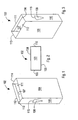
- the outer enclosure 102 is of the box type, having, for example, a parallelepipedon shape.
- the outer enclosure 102 comprises a base wall 103, from which a front wall 104 and a rear wall 105 extend opposite the front wall 104.
- the front wall 104 comprises an end 141 folded towards the inside of the outer enclosure 102 ( Figures 10 and 11 ).
- the end 141 is fixed to an internal surface of the front wall 104 and acts as an arrest, as will be explained better below, for the internal enclosure 116.
- the rear wall 105 comprises a further end 142 folded towards the inside of the outer enclosure 102 ( Figures 10 and 11 ).
- the further end 142 is fixed to a further internal surface of the rear wall 105.
- first side wall 106 and a second side wall 110 are interposed, each of which has a reduced extension compared with the front wall 104 and the rear wall 105.
- the outer enclosure 102 further comprises an opening 107 opposite the base wall 103.
- the opening 107 has a substantially rectangular shape, and is bounded by a first upper edge 111 of the front wall 104, by a second upper edge 112 of the rear wall 105, substantially parallel to the first upper edge 111, by a third upper edge 113 of the first side wall 106, which is substantially perpendicular to the first upper edge 111, and by a fourth upper edge 114 of the second side wall 110, which is substantially parallel to the third upper edge 113.
- the outer enclosure 102 comprises a first through opening 108 and a second through opening 109 obtained respectively on the first side wall 106 and on the second side wall 110.
- the first through opening 108 and the second through opening 110 are mutually opposite.
- first through opening 108 and the second through opening 109 substantially have the shape of isosceles triangles with rounded vertices, these triangles having smaller bases 115 nearer the opening 107 and which are substantially parallel respectively to the third upper edge 113 and to the fourth upper edge 114.
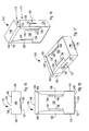
- the packet 101 further comprises an internal enclosure 116 or inner frame, shown in detail in Figures 12 to 17 , arranged for being slidably received in the outer enclosure 102.
- the internal enclosure 116 comprises a containing body 117, for containing the smoke articles, and a closing body including a lid 118 that can be open or closed to enable a consumer to access the smoke articles.
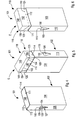
- the lid 118 is movable between an open position ( Figure 9 ) and a closed position ( Figures 7 and 8 ) rotating around a hinge 119, shown for example in Figure 6 .
- the internal enclosure 116 houses an internal wrap 120, shown in Figure 5 and Figures 15 to 18 , comprising a group of smoke articles wrapped in tinfoil or metal foil.
- the internal wrap 120 is of known type and does not have substantial differences compared with the internal wraps used in normal packets of cigarettes.
- the aforesaid containing body 117 of the internal enclosure 116 comprises a main wall 121.
- the main wall 121 include an abutting portion 124, having, for example, a "U"-shaped profile, projecting downwards.
- the abutting portion 124 extends from the main wall 121 on the opposite side of the lid 118.
- a first lesser wall 122 and a second lesser wall 123 are connected to the main wall 130 to contain the internal wrap 120 laterally.
- the internal enclosure 116 further comprises first elastic protruding elements 127, and second elastic protruding elements 128, respectively obtained in the, and projecting outside the first lesser wall 122 and second lesser wall 123.
- the first elastic protruding elements 127 and the second protruding elements 128 have an arrow-tip shape, protrude towards the outside of the internal enclosure 116, and are arranged for engaging in a releasable manner respectively with a first edge zone 129 ( Figure 4 ) of the lesser base 115 of the first through opening 108 and with a second edge zone 130 ( Figure 6 ) of the lesser base 115 of the second through opening 109.
- the first elastic protruding elements 127, the second protruding means 128, the first through opening 108 and the second through opening 109 act as coupling means for the packet 101, i.e. enable the internal enclosure 116 to be coupled in a releasable manner with the outer enclosure 102.
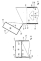
- first elastic protruding elements 127 and the second protruding elements 128 are movable between an everted configuration A ( Figure 7 ) in which they are positioned substantially at respectively the first through opening 108 and the second through opening 109 and project towards the outside of respectively the first lesser wall 122 and the second lesser wall 123, so as to abut on respective active edges 131, 132, of respectively the first edge zone 129 and the second edge zone 130 and cooperate with the latter to maintain the internal enclosure 116 anchored on the outer enclosure 102 in a closed configuration of the packet 101, and a pressed configuration P ( Figures 8 and 9 ) in which they are substantially coplanar respectively with the first lesser wall 122 and the second lesser wall 123 and are respectively disengaged from the first edge zone 129 and from the second edge zone 130 to enable the internal enclosure 116 to slide inside the outer enclosure 102.
- an everted configuration A Figure 7
- they are positioned substantially at respectively the first through opening 108 and the second through opening 109 and project towards the outside of respectively the first lesser wall
- the aforesaid first and second protruding elements 127, 128 each comprise respectively a fin 133 and a further fin 134, that are separated and mutually facing in the pressed configuration P, the fin 133 and the further fin 134 each, for example, having the shape of a rectangular triangle.
- the fin 133 and the further fin 134 are folded outside the internal enclosure 116 at the side of greater length thereof.
- the internal enclosure 116 further comprises through slots 135 obtained in the first lesser wall 122 and in the second lesser wall 123 and positioned above the first elastic protruding elements 127 and the second protruding elements 128.
- the through slots 135 have the shape of a triangle with the vertices rounded, respective contour parts of these through slots 135 being defined respectively by the active edges 131, 132 of the first elastic protruding elements 127 and of the second protruding elements 128.
- the function of the through slots 135 is to promote the movement of the first elastic protruding elements 127 and of the second protruding means 128 between the everted configuration A and the pressed configuration P.
- the first secondary wall 125 and the second secondary wall 126 are folded in front of the internal wrap 120 to contain the latter frontally.
- the first secondary wall 125 and the second secondary wall 126 respectively comprise a first elastic end portion 138, and a second end portion 140, projecting towards the outside of the internal enclosure 116.
- first end portion 138 and the second end portion 140 comprise respectively a first upper abutting edge 144 and a second upper abutting edge 145 arranged for abutting, in an extracted configuration E of the internal enclosure 116 ( Figures 8 and 9 ), an abutting edge 143 of the end 141 of the front wall 104 for preventing the internal enclosure 116 exiting the outer enclosure 102 completely whilst the packet 101 is being used.
- the abutting edge 143 acts as an arrest for the internal enclosure 116.
- first end portion 138, the second end portion 140, and the end 141 act as arresting means for the internal enclosure 116.
- the containing body 117 of the internal enclosure 116 further comprises a bottom wall 146.
- the bottom wall 146 is connected to the main wall 121 and is substantially perpendicular to the aforesaid abutting portion 124.
- the bottom wall 146 is folded below, to contain below, the internal wrap 120.
- the bottom wall 146 faces the base wall 103 of the outer enclosure 102.
- the containing body 117 of the internal enclosure 116 further comprises two lower flaps 147 extending respectively from the first lesser wall 122 and from the second lesser wall 123.
- the lower flaps 147 are folded above the, and glued to the, bottom wall 146, to reinforce the latter.
- the aforesaid main wall 121 of the containing body 117 is connected to the lid 118 by the hinge 119.
- the lid 118 comprises a upper face 148, that, in the closed position, is opposite the base wall 103 and a lower face 151 opposite the upper face 148.
- a front face 149 and a rear face 152 that are opposite one another are connected to the upper face 148, the lower face 151 being fixed to the rear face 152.
- two side faces 150 are interposed, having, for example, a trapezium shape.
- the lid 118 has a substantially box structure.
- the upper face 148 is contiguous, and substantially coplanar, with the first upper edge 111, with the second upper edge 112, with the third upper edge 113 and with the fourth upper edge 114.
- the side faces 150 are contiguous, and substantially coplanar, respectively with the first lesser wall 122 and with the second lesser wall 123.
- the front face 149 of the lid 118 faces the folded end 141 of the front wall 104.
- an edge 153 of the front face 149 abuts on upper edge portions 154 of the first secondary wall 125 and of the second secondary wall 126.
- the packet 101 further comprises a flat spring 155 or leaf spring to push the internal enclosure 116 away from the base wall 103 of the outer enclosure 102.
- the flat spring 155 is arranged for partially drawing out, through the opening 107, the internal enclosure 116 from the outer enclosure 102, to enable the consumer to access the smoke articles, as will be explained better below.
- the flat spring 155 is made of biodegradable plastics, for example maize-based biodegradable plastics.
- the flat spring 155 is folded so as to be substantially "C"-shaped in an operating configuration.
- the flat spring 155 is movable between a compact configuration R ( Figure 7 ) when the packet 101 is closed, and an extended configuration S ( Figures 8 and 9 ) when the packet 101 is open.
- the flat spring 155 extends and acts substantially along the entire length of the bottom wall 146 of the internal enclosure 116.
- the flat spring 155 is interposed and acts between the base wall 103 and the bottom wall 146.
- the flat spring 146 is positioned in a further gap 158 bounded above by the bottom wall 146, below by the base wall 103, frontally by the front wall 104, rearly by the rear wall 105 and laterally by the first side wall 106 and by the second side wall 110.
- the flat spring 155 comprises a first end 156, extending along the width of the packet 101, engaging a first corner 159 defined between the base wall 103 and the rear wall 105.
- the flat spring 155 further comprises a second end 157, extending along the width of the packet 101, engaging a second corner 160 defined between the bottom wall 146 and the abutting portion 124.
- the consumer can retain the packet 101 with a hand and act, or press with the thumb and forefinger of the same hand both on the first elastic protruding elements 127 and on the second protruding elements 128 to move the elastic protruding elements 127 and the second protruding elements 128 from the everted configuration A to the pressed configuration P in which, as said, they are respectively disengaged from the first through opening 108 and from the second through opening 1090.
- the consumer can rotate the lid 118 to the open position ( Figure 9 ) and access the smoke articles.
- the consumer After removing one or more smoke articles, the consumer can position, with the thumb of the hand with which he holds the packet 101, the lid 118 in the closed position. Subsequently, the consumer can push the internal enclosure 116 inside the outer enclosure 102, by acting on the lid 118 in contrast to the flat spring 155, until the first elastic protruding elements 127 and the second protruding elements 128 are positioned in the everted configuration A, in which, as already mentioned, they cooperate respectively with the first through opening 108 and with the second through opening 109 to keep the packet 101 closed.
- the packet 101 enables, via the spring 155, the internal enclosure 116 to exit the outer enclosure 102, without the need to press the internal enclosure 116 with force.
- first elastic protruding elements 127 and of the second protruding elements 128 enables accidental opening of the packet 101 to be avoided.
- the box structure of the lid 118 makes the lid 118 stiffer and more resistant.
- the front face 149 faces the folded end 141 of the front wall 104 ( Figure 10 ) thus promoting sealing of the packet 101.
- the flat spring 155 by extending and acting substantially along the entire width of the bottom wall 146, enables a uniform thrust to be obtained acting on the bottom wall 146 of the internal enclosure 116, which enables any jamming of the internal enclosure 116 in the outer enclosure 102 to be avoided.
- flat spring 155 being made of biodegradable plastics, is easily disposable in nature.
- first through opening 108 and of the second through opening 109 there is provided a single through opening obtained in the first side wall 106, or in the second side wall 110, or in the front wall 104, or in the rear wall 105.
- a single element that protrudes structurally and is functionally similar to the first elastic protruding elements 127 and to the second protruding elements 128.
- first through opening 108 and the second through opening 109 are made on contiguous sides of the packet 101.
- first side wall 106 and on the front wall 104 can be made on the first side wall 106 and on the front wall 104, or on the front wall 104 and on the second side wall 110, or on the second side wall 110 and on the rear wall 105, or on the rear wall 105 and on the first side wall 106.
- first elastic protruding elements 127 and the second protruding elements 128 are made on contiguous sides of the internal enclosure 116.
- first through opening 108 and the second through opening 109 may have any shape, for example elongated, circular, rectangular, polygonal, etc..
- first through opening 108 and the second through opening 109 are positioned at different heights.
- the abutting portion 124 has a profile of any shape, for example triangular, curved, polygonal, etc..
- first elastic protruding elements 127 and/or the second protruding elements 128 may have any shape, for example rectangular.
- first elastic protruding elements 127 and the second protruding elements 128 comprise a single wing having any shape, for example triangular, or rectangular, or curved, etc..
- the through slots 135 can have any shape, for example, rectangular or semicircular.
- the flat spring 155 is made of metal.
- the flat spring 155 instead of the flat spring 155 it is possible to use any type of elastic means, for example a helical spring.
- any type of elastic means for example a helical spring.
- the packet according to the invention may nevertheless also comprise one or more smoothed longitudinal or transverse corners or one or more rounded longitudinal or transverse corners.
- the packet according to the invention may have the shape of an octagonal packet or of a so-called round-corner packet.
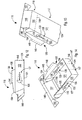
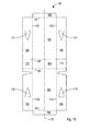
- the aforesaid outer enclosure 102 is formed by folding a blank 161 of the type shown in Figure 19 , made, for example, of card.
- the blank 161 extends along a first longitudinal axis Z1, which can be an axis of symmetry.
- the blank 161 comprises a first central panel 162 intended for forming, in the outer enclosure 102, the front wall 104.
- the blank 161 comprises a second central panel 163 intended for forming, in the outer enclosure 102, the rear wall 105.
- the blank 161 further comprises a transverse panel 164 intended for forming the base wall 103 of the outer enclosure 102.
- transverse panel 164 is interposed between, and connected to the first central panel 162 and second central panel 163.
- the second central panel 163, the transverse panel 163 and the first central panel 162 are arranged in sequence along the first longitudinal axis Z1.
- the first central panel 162 is further connected, on an opposite side of the transverse panel 164, to a first end fold 165 arranged for being folded by 180° and for being glued to the first central panel 162 to stiffen a peripheral zone of the front wall 104 and form the end 141 of the front wall 104.
- the second central panel 163 is further connected, on an opposite side of the transverse panel 164, to a second end fold 166 arranged for being folded by 180° and for being glued to the second central panel 163 to stiffen a further peripheral zone of the rear wall 105 and form the further end 142 of the rear wall 105.
- the second end fold 166, the second central panel 163, the transverse panel 164, the first central panel 162 and the first end fold 165 are arranged in sequence along the first longitudinal axis Z1.
- the blank 161 further comprises first transverse creases 167, arranged transversely, in particular perpendicularly, to the first longitudinal axis Z1, to connect together the second end fold 166, the second central panel 163, the transverse panel 164, the first central panel 162 and the first end fold 165.
- the blank 161 further comprises a pair of first outer panels 168, arranged on the two sides of the first central panel 162 in a region defined between the first end fold 165 and the transverse panel 164.
- first outer panels 168 are intended to form the first side wall 106 and the second side wall 110 of the outer enclosure 102.
- the second outer panels 169 are fixed to respective internal walls of the first outer panels 168, so as to reinforce the first side wall 106 and the second side wall 110.
- the first outer panels 168 and the second outer panels 169 are connected respectively to the first central panel 162 and to the second central panel 163 along first longitudinal creases 170, that are substantially parallel to the first longitudinal axis Z1.
- the first outer panels 168 and the second outer panels 169 each comprise respectively a first opening 171 and a second opening 172, having substantially a triangular shape with rounded vertices.
- Each first opening 171 is arranged for cooperating with a corresponding second opening 172 for forming, in the packet 101, respectively the first through opening 108 and the second through opening 109.
- the second outer panels 169 each comprise a respective recess 173, having substantially the shape of a rounded "V" extending transversely, in particular perpendicularly, with respect to the first longitudinal axis Z1, the vertex of the "V" facing the first longitudinal axis Z1.
- Such recesses 173, which are substantially symmetrical to the first longitudinal axis Z1, are arranged for enabling, in an assembling step of the packet 101, a pushing element to insert the flat spring 155 between the base wall 103 and the bottom wall 146.
- first wings 174 are further connected that are arranged for being folded inside the second outer panels 169 and being glued to the transverse panel 164 so as to stiffen the base wall 103.
- Figure 20 shows an inner frame 175 that can be used to form the internal enclosure 116.
- the inner frame 175 extends along a second longitudinal axis Z2, which can be an axis of symmetry.
- the inner frame 175 can be made of card, possibly coupled with a sheet of metal, such as aluminium.
- the inner frame 175 comprises an intended folded line 176, intended for giving rise, in the packet 101, to the hinge 119.
- the intended folded line 176 may comprise a crease or be formed by a plurality of cuts separated by joining dots.
- the external weakening lines 179 and the internal weakening lines 178 extend substantially parallelly to the second longitudinal axis Z2.
- the external weakening lines 179 are arranged outside the internal weakening lines 178.
- a first transverse weakening line 180 arranged transversely to the internal and external weakening lines 178 and 179, is further obtained in a lower region of the inner frame 175.
- the first transverse weakening line 180 comprises a shaped cut 185 arranged for defining a contour of the abutting portion 124.
- a second transverse weakening line 181, a third transverse weakening line 182, a fourth transverse weakening line 183 and a fifth transverse weakening line 184, arranged transversely to the internal and external weakening lines 178 and 179, are obtained in an upper region of the inner frame 175.
- the second transverse weakening line 181, the third transverse weakening line 182, the fourth transverse weakening line 183 and the fifth transverse weakening line 184 are arranged in sequence along the second longitudinal axis Z2.
- the internal weakening lines 178 and the first transverse weakening line 180 there is defined a main panel 177 of the inner frame 175, the main panel 177 being intended for forming, in the internal enclosure 116, the main wall 121.
- the side panels 186 are intended to form the first lesser wall 122 and the second lesser wall 123 of the internal enclosure 116.
- the inner frame 175 further comprises two pairs of oblique creases 187 made in the side panels 186.
- the oblique creases 187 are transverse to the second longitudinal axis Z2, each pair cooperating for forming a "V"-shaped profile
- these profiles are specular with respect to the second longitudinal axis Z2.
- the inner frame 175 comprises, in each of the side panels 186, a first element 188 and a second element 189 that are separated from one another and have been previously suitably folded outwards the inner frame 175 around respective oblique creases 187, the first element 188 and the second element 189 being intended to form the fin 133 and the further fin 134.
- the inner frame 175 comprises a pair of further shaped cuts 190, having, for example, a triangular shape with rounded vertices, each obtained, for example by cutting or punching, in a side panel 186 above the first elements 188 and the second elements 189, the shaped cuts 190 being intended to form the through slots 135.
- peripheral panels 191 are folded in front of the internal wrap 120 to form respectively the first secondary wall 125 and the second secondary wall 126.
- the inner frame 17 after being folded, surrounds the internal wrap 120 on four sides.
- the inner frame 175 further comprises longitudinal creases 192 extending substantially parallelly to the second longitudinal axis Z2.
- the longitudinal creases 192 are obtained in the peripheral panels 191 and are arranged outside the external weakening lines 179.
- the inner frame 175 comprises, in each of the peripheral panels 191, an element 193 that have been previously suitably folded outwards the inner frame 175 around the respective longitudinal crease 192 to form the first end portion 138 and the second end portion 140. Between the first transverse weakening line 180 and a lower transverse profile 194 of the inner frame 175 there is defined a first end panel 195, suitable for being folded below the internal wrap 120 for obtaining the bottom wall 146.
- first transverse weakening line 180 To ends of the side panels 186 there are further connected, by the first transverse weakening line 180, second wings 174 arranged for forming the lower flaps 147.
- the second wings 174 are arranged for being folded inside the side panels 186 and being glued inside the end panel 195 so as to stiffen the bottom wall 146.
- the inner frame 175 further comprises a first transverse panel 197 connected to the main panel 177 by the intended folded line 176, the first transverse panel 197 being intended for forming the rear face 152 of the lid 118.
- the first transverse panel 197 is bounded below by the folding line 176, above by the third transverse weakening line 182, and laterally by the internal weakening lines 178.
- the inner frame 175 further comprises third wings 198, substantially having the form of a trapezium, that are arranged at the sides of the first transverse panel 197 and connected to the first transverse panel 197 by the internal weakening lines 178.
- the third wings 198 are arranged for strengthening, when the inner frame 175 is folded to form the internal enclosure 116, the-side faces 150 of the lid 118.
- Each third wing 198 is separated from the corresponding side panel 186 by a tilted cut 199.
- the inner frame 175 comprises a second transverse panel 200 intended for forming, when the inner frame 175 is folded to form the internal enclosure 116, the upper face 148 of the lid 118.
- the second transverse panel 200 is bounded below by the second transverse weakening line 181 and above by the third transverse weakening line 182.
- the inner frame 175 comprises a third transverse panel 201 intended for forming, when the inner frame 175 is folded to form the internal enclosure 116, the front face 149 of the lid 118.
- the third transverse panel 201 is bounded below by the third transverse weakening line 182 and above by the fourth transverse weakening line 183.
- the inner frame 175 further comprises fourth wings 202, substantially having the form of a trapezium, that are arranged at the sides of the third transverse panel 201 and connected to the third transverse panel 201 by the internal weakening lines 178.
- the fourth wings 202 are intended for forming, when the inner frame 175 is folded to form the internal enclosure 116, the side faces 150 of the lid 118.
- the fourth wings 202 are arranged for being fixed, in particular glued, to respective external surfaces of the third wings 198.
- the inner frame 175 comprises a fourth transverse panel 203 intended for forming, when the inner frame 175 is folded to form the internal enclosure 116, the lower face 151 of the lid 118.
- the fourth transverse panel 203 is bounded below by the fourth transverse weakening line 183 and above by the fifth transverse weakening line 184.
- the fourth transverse panel 203 is further connected, by the fifth transverse weakening line 184, to an end fold 204 arranged for being glued, when the inner frame 175 is folded to form the internal enclosure 116, to an internal surface of the first transverse panel 197.
- the inner frame 175 is folded around the internal wrap 120 and is made adherent thereto by glue points positioned in a similar manner to what occurs in traditional inner frames.
- the inner frame 175 can be folded around the internal wrap 120 using a folding unit that is similar to that used for the traditional inner frames.
- the outer enclosure 102 is then constructed by folding the blank 161 around the internal enclosure 116.
- the transverse panel 164 to which the first wings 174 were previously fixed, the second central panel 163, to which the second end fold 166 was previously fixed, and the second outer panels 169 are initially folded around the internal enclosure 116.
- the flat spring 155 is inserted between the transverse panel 164 and the end panel 195 by the aforesaid pushing element suitably inserted into the partially assembled packet 101 through the recesses 173.
- the first central panel 162 to which the first end fold 165 has been previously fixed, and the first outer panels 168 which are fixed, for example by glue points, each on a corresponding second outer panel 169, are folded around the internal enclosure 116.
- the recesses 173 are not visible, as they are covered by the first outer panels 168.
- the packet 101 can be made using packaging machines that do not substantially differ from existing machines.
Landscapes
- Engineering & Computer Science (AREA)
- Mechanical Engineering (AREA)
- Cartons (AREA)
Claims (19)
- Paquet d'articles à fumer comprenant une enveloppe interne (116) pour contenir lesdits articles à fumer, une enveloppe externe (102) pour recevoir à coulisse ladite enveloppe interne (116), ladite enveloppe externe (102) comprenant une ouverture (107) à travers laquelle ladite enveloppe interne (116) peut sortir, et des moyens élastiques (155), interposés entre une paroi de base (103) de ladite enveloppe externe (102) à l'opposé de ladite ouverture (107) et une paroi inférieure (146) de ladite enveloppe interne (116) faisant face à ladite paroi de base (103), pour éloigner ladite enveloppe interne (116) de ladite base (103), caractérisé en ce qu'il est prévu des moyens de raccordement (108,109,127,128) obtenus dans des moyens de paroi (104,105,106,110,121,122,123) dudit paquet (101) pour raccorder ladite enveloppe interne (116) avec ladite enveloppe (102) d'une manière amovible.
- Paquet selon la revendication 1, dans lequel lesdits moyens élastiques (155) s'étendent et agissent le long d'une partie prédominante de ladite paroi inférieure (146).
- Paquet selon la revendication 1 ou 2, dans lequel lesdits moyens élastiques (155) s'étendent et agissent substantiellement sur toute la largeur de ladite paroi inférieure (146).
- Paquet selon l'une quelconque des revendications précédentes, dans lequel lesdits moyens élastiques comprennent des moyens formant ressort (155).
- Paquet selon l'une quelconque des revendications précédentes, dans lequel lesdits moyens élastiques comprennent un ressort plat (155).
- Paquet selon la revendication 5, dans lequel ledit ressort plat (155) est fait de plastique biodégradable ou de métal.
- Paquet selon l'une quelconque des revendications précédentes, dans lequel lesdits moyens de raccordement (108,109,127,128) sont obtenus dans une paroi (104,105,106,121,122,123) desdits moyens formant paroi.
- Paquet selon l'une quelconque des revendications 1 à 6, dans lequel lesdits moyens de raccordement (108,109,127,128) sont obtenus dans une paire de parois opposées (104,105 ; 106,110 ;122,123) desdits moyens formant paroi (104,105,106,110,121,122,123).
- Paquet selon l'une quelconque des revendications 1 à 6, dans lequel lesdits moyens de raccordement (108, 109,127,128) sont obtenus dans une paire de parois consécutives (104,106 ;104,110 ;105,106 ;105,110 ;121,122 ; 121,123) desdits moyens formant paroi.
- Paquet selon l'une quelconque des revendications précédentes, dans lequel lesdits moyens de raccordement (108,109,127,128) comprennent des moyens formant ouverture traversante (108,109) obtenus dans ladite enveloppe externe (102).
- Paquet selon la revendication 10, dans lequel lesdits moyens de raccordement (108,109,127,128) comprennent des moyen élastiques faisant saillie (127,128) obtenus dans, et faisant saillie à l'extérieur de, ladite enveloppe interne (116) et agencés pour venir en prise d'une manière amovible avec lesdits moyens formant ouverture traversante (108,109).
- Paquet selon la revendication 11, dans lequel lesdits moyens élastiques faisant saillie (127, 128) sont déplaçables entre une configuration renversée (A) dans laquelle lesdits moyens élastiques faisant saillie (127,128) sont en prise avec ladite ouverture traversante (108,109) pour maintenir, dans une configuation fermée dudit paquet (101), ladite enveloppe interne (116) ancrée dans ladite enveloppe externe (102), et une configuration pressée (P) dans laquelle lesdits moyens élastiques faisant saillie (127,128) sont dégagés desdits moyens formant ouverture traversante (108,109) pour permettre à ladite enveloppe interne (116) de glisser à l'intérieur de ladite enveloppe externe (102).
- Paquet selon l'une quelconque des rêvendications précédentes, dans lequel ladite enveloppe interne (116) comprend un corps formant contenant (117) agencé pour loger lesdits articles à fumer et un organe de fermeture (118) articulé sur ledit corps formant contenant (117).
- Paquet selon la revendication 13, dans laquel ledit organe de fermeture comprend un couvercle (118) ayant une structure de boîte.
- Paquet selon la revendication 14, dans lequel ledit couvercle (119) comprend une face frontale (149) agencée, dans une configuration fermée dudit paquet (101), pour faire face à et coopérer avec une partie de paroi (141) de ladite enveloppe externe (102) pour empêcher de petites parties desdits articles à fumer, en particulier des résidus de tabac, de sortir dudit paquet (101).
- Paquet selon l'une quelconque des revendications précédentes, et comprenant des moyens d'arrêt (138,140,141) pour empêcher ladite enveloppe interne (116) de sortir complètement de ladite enveloppe externe (102).
- Paquet selon la revendication 16, dans lequel lesdits moyens d'arrêt (138,140,143) comprennent au moins une partie d'extrémités (138,140) faisant saillie vers l'extérieur d'une paroi secondaire (125,126) de ladite enveloppe interne (116).
- Paquet selon la revendication 17, lorsque la revendication 16 se rattache à la revendication 15, dans lequel lesdits moyens d'arrêt (138,140,141) comprennent un bord formant butée (143) de ladite partie de paroi (141) agencé pour venir en butée contre ladite au moins une partie d'extrémité (138,140).
- Paquet selon l'une quelconque des revendications précédentes, dans lequel ladite enveloppe interne (116) comprend une partie formant butée (124) faisant saillie vers ladite paroi de base (103) et agencée pour agir comme une butée pour lesdits moyens élastiques (155).
Priority Applications (1)
| Application Number | Priority Date | Filing Date | Title |
|---|---|---|---|
| PL08875746T PL2361204T3 (pl) | 2008-11-20 | 2008-11-20 | Opakowanie na wyroby tytoniowe |
Applications Claiming Priority (1)
| Application Number | Priority Date | Filing Date | Title |
|---|---|---|---|
| PCT/IB2008/003154 WO2010058237A1 (fr) | 2008-11-20 | 2008-11-20 | Paquet d'articles à fumer, découpe et armature intérieure correspondantes |
Publications (2)
| Publication Number | Publication Date |
|---|---|
| EP2361204A1 EP2361204A1 (fr) | 2011-08-31 |
| EP2361204B1 true EP2361204B1 (fr) | 2013-06-12 |
Family
ID=40727175
Family Applications (1)
| Application Number | Title | Priority Date | Filing Date |
|---|---|---|---|
| EP08875746.3A Not-in-force EP2361204B1 (fr) | 2008-11-20 | 2008-11-20 | Paquet d'articles a fumer |
Country Status (3)
| Country | Link |
|---|---|
| EP (1) | EP2361204B1 (fr) |
| PL (1) | PL2361204T3 (fr) |
| WO (1) | WO2010058237A1 (fr) |
Families Citing this family (9)
| Publication number | Priority date | Publication date | Assignee | Title |
|---|---|---|---|---|
| IT1402725B1 (it) * | 2010-11-24 | 2013-09-18 | Gd Spa | Confezione di articoli da fumo. |
| GB2498733A (en) | 2012-01-25 | 2013-07-31 | British American Tobacco Co | A Smoking Article Pack for Removing Articles Sideways |
| GB2506124A (en) * | 2012-09-20 | 2014-03-26 | British American Tobacco Co | Pack with inner and outer components for smoking articles, with dampened biasing member |
| GB2530090A (en) * | 2014-09-15 | 2016-03-16 | British American Tobacco Co | Pack For Tobacco Industry Products |
| PL3243766T3 (pl) | 2016-05-13 | 2019-08-30 | Fontem Holdings 1 B.V. | Opakowanie do pomieszczenia produktów |
| IT201800020494A1 (it) * | 2018-12-20 | 2020-06-20 | Gd Spa | Pacchetto rigido di articoli da fumo provvisto di un coperchio incernierato e scorrevole |
| WO2021032621A1 (fr) | 2019-08-16 | 2021-02-25 | Philip Morris Products S.A. | Récipient ayant une boîte et un manchon avec mécanisme de verrouillage |
| WO2021059095A1 (fr) * | 2019-09-23 | 2021-04-01 | Philip Morris Products S.A. | Contenant à couvercle à charnière coulissant doté d'un mécanisme de verrouillage |
| IT202000001873A1 (it) | 2020-01-31 | 2021-07-31 | Gd Spa | Pacchetto rigido di articoli da fumo provvisto di un coperchio incernierato e scorrevole |
Family Cites Families (3)
| Publication number | Priority date | Publication date | Assignee | Title |
|---|---|---|---|---|
| GB205750A (en) * | 1923-01-15 | 1923-10-25 | Edwin James Wright | Improvements in or relating to cigarette cases |
| DE1967145U (de) * | 1967-05-03 | 1967-08-24 | Osthushenrich Kg | Stuelpdeckelschachtel. |
| DE19614043B4 (de) * | 1996-04-10 | 2005-07-28 | Focke Gmbh & Co. Kg | Klappschachtel für eine Zigaretten-Gruppe oder dergleichen |
-
2008
- 2008-11-20 EP EP08875746.3A patent/EP2361204B1/fr not_active Not-in-force
- 2008-11-20 WO PCT/IB2008/003154 patent/WO2010058237A1/fr not_active Ceased
- 2008-11-20 PL PL08875746T patent/PL2361204T3/pl unknown
Also Published As
| Publication number | Publication date |
|---|---|
| PL2361204T3 (pl) | 2014-01-31 |
| WO2010058237A1 (fr) | 2010-05-27 |
| EP2361204A1 (fr) | 2011-08-31 |
Similar Documents
| Publication | Publication Date | Title |
|---|---|---|
| EP2361204B1 (fr) | Paquet d'articles a fumer | |
| EP2580134B1 (fr) | Emballage par ouverture coulissante d'articles de tabac | |
| KR101244532B1 (ko) | 측개방형의 경첩식 뚜껑을 갖는상자 | |
| US7562772B2 (en) | Container blank for a box with hinged lid | |
| JP4205587B2 (ja) | ヒンジ式蓋部を備えたタバコ製品用の剛体のパケット | |
| US8511462B2 (en) | Multi-product packet | |
| US7891542B2 (en) | Slide and shell container | |
| EP1931570B1 (fr) | Paquet rigide à ouverture à glissière pour articles de tabac | |
| KR101483317B1 (ko) | 흡연 물품용 팩 | |
| EP2646345B1 (fr) | Paquet de cigarettes | |
| JP2014509289A (ja) | 喫煙品用パッケージ | |
| EP1725460B1 (fr) | Etui rigide pour articles de tabac | |
| JP2006500296A (ja) | タバコ製品用側開放硬質包装容器 | |
| KR101541841B1 (ko) | 끽연품용 패킷 및 대응 카드보드 백지 | |
| EP2271557A1 (fr) | Paquet pour articles à fumer et découpe correspondante | |
| EP2340221B1 (fr) | Paquet d'articles à fumer | |
| WO2009040379A1 (fr) | Découpe de paquet de cigarettes et paquet obtenu à partir de celle-ci | |
| WO2017002066A1 (fr) | Paquet à ouverture coulissante d'articles à fumer | |
| US20200331690A1 (en) | Sliding Packs With Flip Top Hinged Lids | |
| US20190092560A1 (en) | Container with top curved bevelled edge | |
| WO2009127892A1 (fr) | Paquet pour articles de tabac et ébauche correspondante | |
| JP2014111480A (ja) | 煙草製品のための箱とそれに対応するボール紙のブランク | |
| JP2009096505A (ja) | 包装箱 |
Legal Events
| Date | Code | Title | Description |
|---|---|---|---|
| PUAI | Public reference made under article 153(3) epc to a published international application that has entered the european phase |
Free format text: ORIGINAL CODE: 0009012 |
|
| 17P | Request for examination filed |
Effective date: 20110513 |
|
| AK | Designated contracting states |
Kind code of ref document: A1 Designated state(s): AT BE BG CH CY CZ DE DK EE ES FI FR GB GR HR HU IE IS IT LI LT LU LV MC MT NL NO PL PT RO SE SI SK TR |
|
| DAX | Request for extension of the european patent (deleted) | ||
| GRAP | Despatch of communication of intention to grant a patent |
Free format text: ORIGINAL CODE: EPIDOSNIGR1 |
|
| RIN1 | Information on inventor provided before grant (corrected) |
Inventor name: VECCHI, MARCO |
|
| GRAS | Grant fee paid |
Free format text: ORIGINAL CODE: EPIDOSNIGR3 |
|
| GRAA | (expected) grant |
Free format text: ORIGINAL CODE: 0009210 |
|
| RAP1 | Party data changed (applicant data changed or rights of an application transferred) |
Owner name: GIMA TT S.R.L. |
|
| AK | Designated contracting states |
Kind code of ref document: B1 Designated state(s): AT BE BG CH CY CZ DE DK EE ES FI FR GB GR HR HU IE IS IT LI LT LU LV MC MT NL NO PL PT RO SE SI SK TR |
|
| REG | Reference to a national code |
Ref country code: GB Ref legal event code: FG4D |
|
| REG | Reference to a national code |
Ref country code: CH Ref legal event code: EP |
|
| REG | Reference to a national code |
Ref country code: AT Ref legal event code: REF Ref document number: 616598 Country of ref document: AT Kind code of ref document: T Effective date: 20130615 |
|
| REG | Reference to a national code |
Ref country code: DE Ref legal event code: R081 Ref document number: 602008025353 Country of ref document: DE Owner name: GIMA TT S.P.A., IT Free format text: FORMER OWNER: GIMA TT S.R.L., ZOLA PREDOSA, (BOLOGNA), IT |
|
| RAP2 | Party data changed (patent owner data changed or rights of a patent transferred) |
Owner name: GIMA TT S.R.L. |
|
| REG | Reference to a national code |
Ref country code: IE Ref legal event code: FG4D |
|
| REG | Reference to a national code |
Ref country code: DE Ref legal event code: R096 Ref document number: 602008025353 Country of ref document: DE Effective date: 20130808 |
|
| PG25 | Lapsed in a contracting state [announced via postgrant information from national office to epo] |
Ref country code: SE Free format text: LAPSE BECAUSE OF FAILURE TO SUBMIT A TRANSLATION OF THE DESCRIPTION OR TO PAY THE FEE WITHIN THE PRESCRIBED TIME-LIMIT Effective date: 20130612 Ref country code: NO Free format text: LAPSE BECAUSE OF FAILURE TO SUBMIT A TRANSLATION OF THE DESCRIPTION OR TO PAY THE FEE WITHIN THE PRESCRIBED TIME-LIMIT Effective date: 20130912 Ref country code: ES Free format text: LAPSE BECAUSE OF FAILURE TO SUBMIT A TRANSLATION OF THE DESCRIPTION OR TO PAY THE FEE WITHIN THE PRESCRIBED TIME-LIMIT Effective date: 20130923 Ref country code: SI Free format text: LAPSE BECAUSE OF FAILURE TO SUBMIT A TRANSLATION OF THE DESCRIPTION OR TO PAY THE FEE WITHIN THE PRESCRIBED TIME-LIMIT Effective date: 20130612 Ref country code: FI Free format text: LAPSE BECAUSE OF FAILURE TO SUBMIT A TRANSLATION OF THE DESCRIPTION OR TO PAY THE FEE WITHIN THE PRESCRIBED TIME-LIMIT Effective date: 20130612 Ref country code: GR Free format text: LAPSE BECAUSE OF FAILURE TO SUBMIT A TRANSLATION OF THE DESCRIPTION OR TO PAY THE FEE WITHIN THE PRESCRIBED TIME-LIMIT Effective date: 20130913 Ref country code: LT Free format text: LAPSE BECAUSE OF FAILURE TO SUBMIT A TRANSLATION OF THE DESCRIPTION OR TO PAY THE FEE WITHIN THE PRESCRIBED TIME-LIMIT Effective date: 20130612 |
|
| REG | Reference to a national code |
Ref country code: AT Ref legal event code: MK05 Ref document number: 616598 Country of ref document: AT Kind code of ref document: T Effective date: 20130612 |
|
| REG | Reference to a national code |
Ref country code: NL Ref legal event code: VDEP Effective date: 20130612 |
|
| REG | Reference to a national code |
Ref country code: LT Ref legal event code: MG4D |
|
| PG25 | Lapsed in a contracting state [announced via postgrant information from national office to epo] |
Ref country code: HR Free format text: LAPSE BECAUSE OF FAILURE TO SUBMIT A TRANSLATION OF THE DESCRIPTION OR TO PAY THE FEE WITHIN THE PRESCRIBED TIME-LIMIT Effective date: 20130612 Ref country code: BG Free format text: LAPSE BECAUSE OF FAILURE TO SUBMIT A TRANSLATION OF THE DESCRIPTION OR TO PAY THE FEE WITHIN THE PRESCRIBED TIME-LIMIT Effective date: 20130912 |
|
| PG25 | Lapsed in a contracting state [announced via postgrant information from national office to epo] |
Ref country code: LV Free format text: LAPSE BECAUSE OF FAILURE TO SUBMIT A TRANSLATION OF THE DESCRIPTION OR TO PAY THE FEE WITHIN THE PRESCRIBED TIME-LIMIT Effective date: 20130612 |
|
| PG25 | Lapsed in a contracting state [announced via postgrant information from national office to epo] |
Ref country code: BE Free format text: LAPSE BECAUSE OF FAILURE TO SUBMIT A TRANSLATION OF THE DESCRIPTION OR TO PAY THE FEE WITHIN THE PRESCRIBED TIME-LIMIT Effective date: 20130612 Ref country code: IS Free format text: LAPSE BECAUSE OF FAILURE TO SUBMIT A TRANSLATION OF THE DESCRIPTION OR TO PAY THE FEE WITHIN THE PRESCRIBED TIME-LIMIT Effective date: 20131012 Ref country code: CZ Free format text: LAPSE BECAUSE OF FAILURE TO SUBMIT A TRANSLATION OF THE DESCRIPTION OR TO PAY THE FEE WITHIN THE PRESCRIBED TIME-LIMIT Effective date: 20130612 Ref country code: EE Free format text: LAPSE BECAUSE OF FAILURE TO SUBMIT A TRANSLATION OF THE DESCRIPTION OR TO PAY THE FEE WITHIN THE PRESCRIBED TIME-LIMIT Effective date: 20130612 Ref country code: SK Free format text: LAPSE BECAUSE OF FAILURE TO SUBMIT A TRANSLATION OF THE DESCRIPTION OR TO PAY THE FEE WITHIN THE PRESCRIBED TIME-LIMIT Effective date: 20130612 Ref country code: PT Free format text: LAPSE BECAUSE OF FAILURE TO SUBMIT A TRANSLATION OF THE DESCRIPTION OR TO PAY THE FEE WITHIN THE PRESCRIBED TIME-LIMIT Effective date: 20131014 Ref country code: AT Free format text: LAPSE BECAUSE OF FAILURE TO SUBMIT A TRANSLATION OF THE DESCRIPTION OR TO PAY THE FEE WITHIN THE PRESCRIBED TIME-LIMIT Effective date: 20130612 |
|
| REG | Reference to a national code |
Ref country code: PL Ref legal event code: T3 |
|
| PG25 | Lapsed in a contracting state [announced via postgrant information from national office to epo] |
Ref country code: RO Free format text: LAPSE BECAUSE OF FAILURE TO SUBMIT A TRANSLATION OF THE DESCRIPTION OR TO PAY THE FEE WITHIN THE PRESCRIBED TIME-LIMIT Effective date: 20130612 Ref country code: NL Free format text: LAPSE BECAUSE OF FAILURE TO SUBMIT A TRANSLATION OF THE DESCRIPTION OR TO PAY THE FEE WITHIN THE PRESCRIBED TIME-LIMIT Effective date: 20130612 |
|
| PLBE | No opposition filed within time limit |
Free format text: ORIGINAL CODE: 0009261 |
|
| STAA | Information on the status of an ep patent application or granted ep patent |
Free format text: STATUS: NO OPPOSITION FILED WITHIN TIME LIMIT |
|
| PG25 | Lapsed in a contracting state [announced via postgrant information from national office to epo] |
Ref country code: DK Free format text: LAPSE BECAUSE OF FAILURE TO SUBMIT A TRANSLATION OF THE DESCRIPTION OR TO PAY THE FEE WITHIN THE PRESCRIBED TIME-LIMIT Effective date: 20130612 |
|
| 26N | No opposition filed |
Effective date: 20140313 |
|
| REG | Reference to a national code |
Ref country code: DE Ref legal event code: R097 Ref document number: 602008025353 Country of ref document: DE Effective date: 20140313 |
|
| REG | Reference to a national code |
Ref country code: CH Ref legal event code: PL |
|
| GBPC | Gb: european patent ceased through non-payment of renewal fee |
Effective date: 20131120 |
|
| PG25 | Lapsed in a contracting state [announced via postgrant information from national office to epo] |
Ref country code: LI Free format text: LAPSE BECAUSE OF NON-PAYMENT OF DUE FEES Effective date: 20131130 Ref country code: CH Free format text: LAPSE BECAUSE OF NON-PAYMENT OF DUE FEES Effective date: 20131130 |
|
| REG | Reference to a national code |
Ref country code: FR Ref legal event code: ST Effective date: 20140731 |
|
| REG | Reference to a national code |
Ref country code: IE Ref legal event code: MM4A |
|
| PG25 | Lapsed in a contracting state [announced via postgrant information from national office to epo] |
Ref country code: IE Free format text: LAPSE BECAUSE OF NON-PAYMENT OF DUE FEES Effective date: 20131120 |
|
| PG25 | Lapsed in a contracting state [announced via postgrant information from national office to epo] |
Ref country code: GB Free format text: LAPSE BECAUSE OF NON-PAYMENT OF DUE FEES Effective date: 20131120 Ref country code: FR Free format text: LAPSE BECAUSE OF NON-PAYMENT OF DUE FEES Effective date: 20131202 |
|
| PG25 | Lapsed in a contracting state [announced via postgrant information from national office to epo] |
Ref country code: CY Free format text: LAPSE BECAUSE OF FAILURE TO SUBMIT A TRANSLATION OF THE DESCRIPTION OR TO PAY THE FEE WITHIN THE PRESCRIBED TIME-LIMIT Effective date: 20130612 |
|
| PG25 | Lapsed in a contracting state [announced via postgrant information from national office to epo] |
Ref country code: MC Free format text: LAPSE BECAUSE OF FAILURE TO SUBMIT A TRANSLATION OF THE DESCRIPTION OR TO PAY THE FEE WITHIN THE PRESCRIBED TIME-LIMIT Effective date: 20130612 Ref country code: LU Free format text: LAPSE BECAUSE OF NON-PAYMENT OF DUE FEES Effective date: 20131120 Ref country code: HU Free format text: LAPSE BECAUSE OF FAILURE TO SUBMIT A TRANSLATION OF THE DESCRIPTION OR TO PAY THE FEE WITHIN THE PRESCRIBED TIME-LIMIT; INVALID AB INITIO Effective date: 20081120 |
|
| PG25 | Lapsed in a contracting state [announced via postgrant information from national office to epo] |
Ref country code: MT Free format text: LAPSE BECAUSE OF FAILURE TO SUBMIT A TRANSLATION OF THE DESCRIPTION OR TO PAY THE FEE WITHIN THE PRESCRIBED TIME-LIMIT Effective date: 20130612 |
|
| PGFP | Annual fee paid to national office [announced via postgrant information from national office to epo] |
Ref country code: IT Payment date: 20151023 Year of fee payment: 8 Ref country code: DE Payment date: 20151022 Year of fee payment: 8 |
|
| PGFP | Annual fee paid to national office [announced via postgrant information from national office to epo] |
Ref country code: PL Payment date: 20151026 Year of fee payment: 8 |
|
| REG | Reference to a national code |
Ref country code: DE Ref legal event code: R082 Ref document number: 602008025353 Country of ref document: DE Representative=s name: MAIWALD PATENTANWALTSGESELLSCHAFT MBH, DE Ref country code: DE Ref legal event code: R081 Ref document number: 602008025353 Country of ref document: DE Owner name: GIMA TT S.P.A., IT Free format text: FORMER OWNER: GIMA TT S.R.L., OZZANO DELL'EMILIA, BOLOGNA, IT Ref country code: DE Ref legal event code: R082 Ref document number: 602008025353 Country of ref document: DE Representative=s name: MAIWALD PATENTANWALTS- UND RECHTSANWALTSGESELL, DE |
|
| PGFP | Annual fee paid to national office [announced via postgrant information from national office to epo] |
Ref country code: TR Payment date: 20161111 Year of fee payment: 9 |
|
| REG | Reference to a national code |
Ref country code: DE Ref legal event code: R119 Ref document number: 602008025353 Country of ref document: DE |
|
| PG25 | Lapsed in a contracting state [announced via postgrant information from national office to epo] |
Ref country code: IT Free format text: LAPSE BECAUSE OF NON-PAYMENT OF DUE FEES Effective date: 20161120 |
|
| PG25 | Lapsed in a contracting state [announced via postgrant information from national office to epo] |
Ref country code: DE Free format text: LAPSE BECAUSE OF NON-PAYMENT OF DUE FEES Effective date: 20170601 |
|
| PG25 | Lapsed in a contracting state [announced via postgrant information from national office to epo] |
Ref country code: PL Free format text: LAPSE BECAUSE OF NON-PAYMENT OF DUE FEES Effective date: 20161120 |
|
| PG25 | Lapsed in a contracting state [announced via postgrant information from national office to epo] |
Ref country code: TR Free format text: LAPSE BECAUSE OF NON-PAYMENT OF DUE FEES Effective date: 20171120 |