EP2361583B1 - Système de surveillance de la taille d'ablation - Google Patents
Système de surveillance de la taille d'ablation Download PDFInfo
- Publication number
- EP2361583B1 EP2361583B1 EP11001596.3A EP11001596A EP2361583B1 EP 2361583 B1 EP2361583 B1 EP 2361583B1 EP 11001596 A EP11001596 A EP 11001596A EP 2361583 B1 EP2361583 B1 EP 2361583B1
- Authority
- EP
- European Patent Office
- Prior art keywords
- microwave antenna
- thermal sensors
- tissue
- temperature
- microwave
- Prior art date
- Legal status (The legal status is an assumption and is not a legal conclusion. Google has not performed a legal analysis and makes no representation as to the accuracy of the status listed.)
- Not-in-force
Links
Images


Classifications
-
- A—HUMAN NECESSITIES
- A61—MEDICAL OR VETERINARY SCIENCE; HYGIENE
- A61B—DIAGNOSIS; SURGERY; IDENTIFICATION
- A61B18/00—Surgical instruments, devices or methods for transferring non-mechanical forms of energy to or from the body
- A61B18/18—Surgical instruments, devices or methods for transferring non-mechanical forms of energy to or from the body by applying electromagnetic radiation, e.g. microwaves
- A61B18/1815—Surgical instruments, devices or methods for transferring non-mechanical forms of energy to or from the body by applying electromagnetic radiation, e.g. microwaves using microwaves
-
- A—HUMAN NECESSITIES
- A61—MEDICAL OR VETERINARY SCIENCE; HYGIENE
- A61B—DIAGNOSIS; SURGERY; IDENTIFICATION
- A61B17/00—Surgical instruments, devices or methods
- A61B2017/00017—Electrical control of surgical instruments
- A61B2017/00022—Sensing or detecting at the treatment site
- A61B2017/00084—Temperature
-
- A—HUMAN NECESSITIES
- A61—MEDICAL OR VETERINARY SCIENCE; HYGIENE
- A61B—DIAGNOSIS; SURGERY; IDENTIFICATION
- A61B17/00—Surgical instruments, devices or methods
- A61B2017/00017—Electrical control of surgical instruments
- A61B2017/00022—Sensing or detecting at the treatment site
- A61B2017/00084—Temperature
- A61B2017/00101—Temperature using an array of thermosensors
-
- A—HUMAN NECESSITIES
- A61—MEDICAL OR VETERINARY SCIENCE; HYGIENE
- A61B—DIAGNOSIS; SURGERY; IDENTIFICATION
- A61B18/00—Surgical instruments, devices or methods for transferring non-mechanical forms of energy to or from the body
- A61B2018/00005—Cooling or heating of the probe or tissue immediately surrounding the probe
- A61B2018/00011—Cooling or heating of the probe or tissue immediately surrounding the probe with fluids
- A61B2018/00023—Cooling or heating of the probe or tissue immediately surrounding the probe with fluids closed, i.e. without wound contact by the fluid
-
- A—HUMAN NECESSITIES
- A61—MEDICAL OR VETERINARY SCIENCE; HYGIENE
- A61B—DIAGNOSIS; SURGERY; IDENTIFICATION
- A61B18/00—Surgical instruments, devices or methods for transferring non-mechanical forms of energy to or from the body
- A61B2018/00636—Sensing and controlling the application of energy
- A61B2018/00666—Sensing and controlling the application of energy using a threshold value
-
- A—HUMAN NECESSITIES
- A61—MEDICAL OR VETERINARY SCIENCE; HYGIENE
- A61B—DIAGNOSIS; SURGERY; IDENTIFICATION
- A61B18/00—Surgical instruments, devices or methods for transferring non-mechanical forms of energy to or from the body
- A61B18/18—Surgical instruments, devices or methods for transferring non-mechanical forms of energy to or from the body by applying electromagnetic radiation, e.g. microwaves
- A61B18/1815—Surgical instruments, devices or methods for transferring non-mechanical forms of energy to or from the body by applying electromagnetic radiation, e.g. microwaves using microwaves
- A61B2018/1869—Surgical instruments, devices or methods for transferring non-mechanical forms of energy to or from the body by applying electromagnetic radiation, e.g. microwaves using microwaves with an instrument interstitially inserted into the body, e.g. needles
Definitions
- the present disclosure relates to systems and methods that may be used in tissue ablation procedures. More particularly, the present disclosure relates to systems and methods for monitoring ablation size during tissue ablation procedures in real-time.
- Microwave ablation procedures e.g., such as those performed for menorrhagia, are typically done to ablate the targeted tissue to denature or kill the tissue.
- Many procedures and types of devices utilizing electromagnetic radiation therapy are known in the art.
- Such microwave therapy is typically used in the treatment of tissue and organs such as the prostate, heart, and liver.
- One non-invasive procedure generally involves the treatment of tissue (e.g., a tumor) underlying the skin via the use of microwave energy.
- tissue e.g., a tumor
- the microwave energy is able to non-invasively penetrate the skin to reach the underlying tissue.
- this non-invasive procedure may result in the unwanted heating of healthy tissue.
- the non-invasive use of microwave energy requires a great deal of control.
- one or more types of sensors are operably associated with the microwave ablation device.
- a microwave ablation device that includes a monopole antenna configuration
- an elongated microwave conductor may be in operative communication with a sensor exposed at an end of the microwave conductor. This type of sensor is sometimes surrounded by a dielectric sleeve.
- the foregoing types of sensor(s) is configured to function (e.g., provide feedback to a controller for controlling the power output of a power source) when the microwave ablation device is inactive, i.e., not radiating. That is, the foregoing sensors do not function in real-time.
- the power source is powered off or pulsed off when the sensors are providing feedback (e.g., tissue temperature) to the controller and/or other device(s) configured to control the power source.
- US 6,500,175 B1 discloses an antenna ablation apparatus for cell necrosis.
- the apparatus comprises an electrode for radiating a tissue.
- External floating probes comprising temperature sensors are provided for determining the extension of the ablation. Some of the probes can slide within lumens of the electrode and be positioned in an adapted region of the tissue.
- US 6,132,425 A discloses a cell necrosis apparatus specifically meant for operating a volumetric cell necrosis.
- the apparatus comprises a plurality of electrodes for providing RF energy and which are meant for spatially occupy the space for obtaining a conic ablation volume.
- These electrodes are slidable through an insulation sleeve which surrounds an introducer.
- Sensors for measuring temperature or impedance can be provided in the electrodes in particular at the distal end of each electrode and at the introducer distal end.
- the invention is defined in claim 1.
- the present disclosure provides a system for monitoring ablation size in real-time.
- the system includes a power source including a microprocessor for executing at least one control algorithm.
- a microwave antenna is configured to deliver microwave energy from the power source to tissue to form an ablation zone.
- a series of thermal sensors is operably disposed adjacent a radiating section of the microwave antenna and extends proximally therefrom. The thermal sensors corresponding to a radius of the ablation zone, wherein each thermal sensor generates a voltage when a predetermined threshold tissue temperature is reached corresponding to the radius of the ablation zone.
- the present disclosure provides a microwave antenna adapted to connect to a power source configured for performing an ablation procedure.
- the microwave antenna includes a radiating section configured to deliver microwave energy from the power source to tissue to form an ablation zone.
- the microwave antenna includes a series of thermal sensors operably disposed adjacent the radiating section of the microwave antenna and extending proximally therefrom. The thermal sensors corresponding to a radius of the ablation zone, wherein each thermal sensor generates a voltage when a predetermined threshold tissue temperature is reached corresponding to the radius of the ablation zone.
- the present disclosure also provides a method for monitoring temperature of tissue undergoing , which is however not part of the invention.
- the method includes the initial step of transmitting microwave energy from a power source to a microwave antenna to form a tissue ablation zone.
- a step of the method includes monitoring the proximal propagation of tissue temperature along the microwave antenna as the tissue ablation zone forms.
- Triggering a detection signal when a predetermined tissue temperature is reached at specific points along the microwave antenna is another step of the method.
- the method includes adjusting the amount of microwave energy from the power source to the microwave antenna.
- distal refers to the portion which is furthest from the user and the term “proximal” refers to the portion that is closest to the user.
- proximal refers to the portion that is closest to the user.
- terms such as “above”, “below”, “forward”, “reaward”, etc. refer to the orientation of the figures or the direction of components and are simply used for convenience of description.
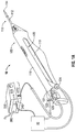
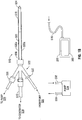
- microwave antenna 100 that is adapted to connect to an electrosurgical power source, e.g., an RF and/or microwave (MW) generator 200 that includes or is in operative communication with one or more controllers 300 and, in some instances, a fluid supply pump 40.
- microwave antenna 100 includes an introducer 116 having an elongated shaft 112 and a radiating or conductive section or tip 114 operably disposed within elongated shaft 112, a cooling assembly 120 having a cooling sheath 121, a handle 118, a cooling fluid supply 122 and a cooling fluid return 124, and an electrosurgical energy connector 126.
- Connector 126 is configured to connect the microwave antenna 100 to the electrosurgical power source 200, e.g., a generator or source of radio frequency energy and/or microwave energy, and supplies electrosurgical energy to the distal portion of the microwave antenna 100.
- Conductive tip 114 and elongated shaft 112 are in electrical communication with connector 126 via an internal coaxial cable 126a that extends from the proximal end of the microwave antenna 100 and includes an inner conductor tip that is operatively coupled to a radiating section 138 operably disposed within the shaft 112 and adjacent the conductive or radiating tip 114 (see FIG. 2A , for example).
- internal coaxial cable 126a includes a dielectric material and an outer conductor surrounding each of the inner conductor tip and dielectric material.
- a connection hub (not shown) disposed at a proximal end of the microwave antenna 100 operably couples connector 126 to internal coaxial cable 126a, and cooling fluid supply 122 and a cooling fluid return 124 to a cooling assembly 120.
- Radiating section 138 by way of conductive tip 114 is configured to deliver radio frequency energy (in either a bipolar or monopolar mode) or microwave energy to a target tissue site.
- Elongated shaft 112 and conductive tip 114 may be formed of suitable conductive material including, but not limited to copper, gold, silver or other conductive metals having similar conductivity values.
- elongated shaft 112 and/or conductive tip 114 may be constructed from stainless steel or may be plated with other materials, e.g., other conductive materials, such as gold or silver, to improve certain properties, e.g., to improve conductivity, decrease energy loss, etc.
- the conductive tip may be deployable from the elongated shaft 112.
- system 10 may be configured for use with a microwave antenna 512 illustrated in FIG. 1A .
- microwave antenna 512 operably couples to generator 200 including a controller 300 via a flexible coaxial cable 516.
- generator 200 is configured to provide microwave energy at an operational frequency from about 500 MHz to about 10 GHz.
- Microwave antenna 512 includes a radiating section or portion 518 that may be connected by a feedline or shaft 520 to coaxial cable 516 that extends from the proximal end of the microwave antenna 512 and includes an inner conductor operably disposed within the shaft 520 and adjacent radiating section 518 and/or a conductive or radiating tissue piercing tip 524.
- the microwave antenna 512 is coupled to the cable 516 through a connection hub 522.
- the connection hub 522 also includes an outlet fluid port 530 (similar to that of cooling fluid return 124) and an inlet fluid port 532 (similar to that of cooling fluid supply 122) that are connected in fluid communication with a sheath 538.
- the sheath 538 encloses the radiating portion 518 and the shaft 520 allowing for coolant fluid from the ports 530 and 532 to be supplied to and circulated around the antenna assembly 512 via respective fluid lumens 530a and 532a.
- the ports 530 and 532 may also couple to supply pump 40.
- microwave antenna 100 For the remainder of the disclosure the operative components associated with the system 10 are described with reference to microwave antenna 100.
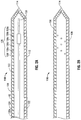
- thermal sensors 136 are operably disposed along a length of the shaft 112 adjacent a radiating section 138 of the microwave antenna 100.
- thermal sensor 136 includes a series of six thermal sensors labeled 136a-136f (collectively referred to as thermal sensors 136).
- a series of thermal sensors is meant to mean at least two thermal sensors.
- Thermal sensors 136 enable physical space sampling of the ablation site.
- Thermal sensors 136 may be operably positioned within an internal portion 150 of the shaft 112. More particularly, the thermal sensors 136 are operably disposed within an internal generally circumferential wall 152 that surrounds and/or defines the cooling fluid supply and fluid return lines 122 and 124, see FIG.
- Thermal sensors 136 may be secured to the circumferential wall 152 via any suitable methods.
- the thermal sensors 136 are secured to the circumferential wall via an epoxy adhesive.
- a plastic or other suitable structure provides mechanical fixation points for the thermal sensors 136.
- the plastic structure e.g., a circumferential or spiral plastic structure
- the plastic structure may be operably disposed within the shaft 112 and couple to one or both of the fluid paths, e.g., supply fluid and return paths 122 and 124.
- Thermal sensors 136 may be disposed along the length of the shaft 112 in any suitable configuration. For example, in the embodiment illustrated in FIG.
- thermal sensors 136 are positioned along the shaft 110 in a linear manner forming a generally linear array along circumferential wall 152 of the shaft 112.
- the thermal sensors 136 may be positioned along circumferential wall 152 of the shaft 112 in a radially offset configuration forming a generally spherical or spiral array ( FIG. 2B ).
- Thermal sensors 136 may be any suitable thermal sensors 136 including but not limited to thermistors, thermocouples, fiber optic sensors, or other device suitable for the intended purpose for monitoring temperature.
- the thermal sensors 136 are six thermocouples 136a-136f. Thermal sensors 136 are in operative communication with a temperature module 332 and/or controller 300.
- the thermal sensors 136 couple to the generator 200 and/or controller 300 via one or more leads, e.g., the internal cable 126a that extends from the proximal end of the microwave antenna 100 and connects to the port 126.
- the thermal sensors 136 may be in operative communication with the generator 200 and/or controller 300 by way of a wireless connection.
- Thermal sensors 136 are configured to provide comprehensive monitoring of an ablation zone "A" ( FIG. 3A ).
- the thermal sensors 136 are configured to generate an analog response (e.g., a voltage, resistance, current, etc.) when a predetermined threshold temperature is reached within the ablation zone "A." More particularly, an initial voltage potential is generated by each of the thermal sensors 136 during transmission of electrosurgical energy from the generator 200 to the microwave antenna 100.
- a predetermined threshold voltage potential is associated with each of thermal sensors 136 and corresponds to a predetermined threshold tissue temperature along a radius of an ablation zone ( FIG. 3A ).
- thermal sensor 136a may be configured to generate an initial voltage potential of 1 volt and a predetermined threshold voltage of 2 volts that corresponds to a threshold tissue temperature of 60° Celsius that corresponds to an ablation zone "A" having a radius r1.
- the analog response indicates to temperature module 332 that a predetermined threshold temperature is reached at the ablation zone (described in more detail below). More particularly, temperature module 332 monitors the thermal sensors 136, e.g., monitors voltage of the thermal sensors 136, and triggers a command signal in response to the thermal sensors 136 reaching a predetermined voltage such that the electrosurgical output power from the generator 200 may be adjusted.
- an amplifier (not shown) may be utilized to amplify the voltage potential generated by the thermal sensors 136.
- each of the thermal sensors 136 may be configured to generate an analog response, e.g., a predetermined voltage, when a predetermined threshold temperature, e.g., a threshold temperature approximately equal to 60° Celsius, has been met such that an ablation zone "A" having a radius r is created.
- a predetermined threshold temperature e.g., a threshold temperature approximately equal to 60° Celsius
- the predetermined threshold temperature associated with a corresponding thermal sensor 136 and a corresponding radius r may be determined via any suitable methods.
- predetermined threshold temperatures may be determined via known experimental data, model equations, or combination thereof.
- one or more control algorithms for predicting tissue ablation size are employed by controller 300. More particularly, the concept of the integration of tissue temperature over time may be used to indicate tissue damage, e.g., death or necrosis.
- the control algorithm utilizes one or more model equations to calculate tissue damage that corresponds to tissue ablation zone size and temperature over time and at different energy levels.
- ⁇ represents damage sustained by tissue and c(t)/c(0) is the ration of the concentration of a component of interest at time equal to the original concentration
- A is equal to the frequency factor
- E a activation energy
- T is temperature (in absolute temperature)
- R is the gas constant.
- the generator 200 includes a controller 300 including one or more modules (e.g., a temperature module 332), a power supply 237, a microwave output stage 238. In this instance, generator 200 is described with respect to the delivery of microwave energy.
- the power supply 237 provides DC power to the microwave output stage 238 which then converts the DC power into microwave energy and delivers the microwave energy to the radiating section 138 of the microwave antenna 100 (see FIG. 2A ).
- the controller 300 may include analog and/or logic circuitry for processing sensed analog responses generated by the thermal sensors 136 and determining the control signals that are sent to the generator 200 and/or supply pump 40 via the microprocessor 335.
- the controller 300 accepts one or more measurements signals indicative of a temperature associated with tissue adjacent an ablation zone and/or the microwave antenna 100, namely, the signals generated as a result of the analog response produced by temperature sensors 136.
- One or more modules e.g., temperature module 332, of the controller 300 monitors and/or analyzes the analog response, e.g., a generated voltage, produced by the temperature sensors 136 and determines if a threshold temperature has been met. If the threshold temperature has been met, then the temperature module, a microprocessor 335 and/or the controller instructs the generator 200 to adjust the microwave output stage 238 and/or the power supply 237 accordingly. Additionally, the controller 300 may also signal the supply pump to adjust the amount of cooling fluid to the microwave antenna 100 and/or the surrounding tissue.
- the controller 200 includes microprocessor 335 having memory 336 which may be volatile type memory (e.g., RAM) and/or non-volitile type memory (e.g., flash media, disk media, etc.).
- the microprocessor 335 is in operative communication with the power supply 237 and/or microwave output stage 238 allowing the microprocessor 335 to control the output of the generator 300 according to either open and/or closed control loop schemes.
- the microprocessor 335 is capable of executing software instructions for processing data received by the temperature module 332, and for outputting control signals to the generator 300 and/or supply pump 40, accordingly.
- the software instructions, which are executable by the controller 300 are stored in the memory 336.
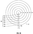
- the microwave antenna 100 of the present disclosure is configured to create an ablation zone "A" having any suitable configuration, such as, for example, spherical ( FIG. 3A ), hemispherical, ellipsoidal ( FIG. 3B where the ablation zone is designated "A-2"), and so forth.
- microwave antenna 100 is configured to create an ablation zone "A” that is spherical ( FIG. 3A ).
- ablation zone "A” is being defined having a plurality of concentric ablation zones having radii r 1 -r 6 when measured from the center of the ablation zone "A,” collectively referred to as radii r.
- a measure of tissue temperature along any radius, e.g., r 3 , associated with ablation zone "A” indicates tissue temperature at similar radii about the entire ablation zone "A.”
- a control algorithm of the present disclosure uses known (or in certain instances predicted) temperatures at specific radii to created an ablation zone "A" having a radius r. That is, temperatures associated with a specific radius are compiled into one or more look-up tables "D" and are stored in memory, e.g., memory 336, accessible by the microprocessor 335 and/or the temperature module 332.
- the temperatures associated with a specific radius and/or one or more look-up tables "D" may be stored into memory during the manufacture process of the generator 200, controller 300 or may be downloaded into memory 336 at a time prior to use of the system 10.
- a temperature of the ablation zone "A” reaches a predetermined threshold temperature
- the analog response produced by one of the corresponding thermal sensors 136 causes temperature module 332 to trigger a command signal to the controller 200 to adjust the power output accordingly.
- This combination of events will provide an ablation zone "A" with a radius approximately equal to r 3 .
- control algorithm, the microprocessor 335 and/or the temperature module 332 may utilize the above Arrhenius Equation to determine a specified amount of tissue damage, e.g., a threshold ⁇ (t), that correlates to ablation zone having a radius r. More particularly, for a given threshold ⁇ ( t ), a threshold temperature "T" may be determined and assigned a suitable voltage value that corresponds to a specific thermal sensor 136, thermal sensor 136c.
- the analog response produced by one of the corresponding thermal sensors 136 causes temperature module 332 to trigger a command signal to the controller 200 to adjust the power output accordingly.
- This combination of events will provide an ablation zone "A" with a radius approximately equal to r 3 .
- one or more control algorithms may utilize interpolation between the radii associated with the thermal sensors 136 to calculate temperatures between discreetly measured radii, e.g., temperatures measured between r 3 and r 4 . More particularly, various (and commonly known) interpolation techniques may be utilized via curve fitting along the thermal sensors 136.
- Temperature module 332 is in operative communication with the plurality of sensors 136 strategically located for sensing various properties or conditions, e.g., tissue temperature, antenna temperature, etc. Temperature module 332 may be a separate module from the microprocessor 335, or temperature module 332 may be included with the microprocessor 335. In an embodiment, the temperature module 332 may be operably disposed on the microwave antenna 100. The temperature module 332 may include control circuitry that receives information from the thermal sensors 136, and provides the information and the source of the information (e.g., the particular temperature sensor, e.g., 136c providing the information) to the controller 300 and/or microprocessor 335.
- the particular temperature sensor e.g., 136c providing the information
- the thermal module 332, microprocessor 335 and/or controller 300 may access look-up table "D" and confirm that the threshold temperature at radius r 3 has been met and, subsequently instruct the generator 200 to adjust the amount of microwave energy being delivered to the microwave antenna.
- look-up table "D" may be stored in a memory storage device (not shown) associated with the microwave antenna 100.
- a look-up table "D" may be stored in a memory storage device operatively associated with handle 118 and/or connector 126 of the microwave antenna 100 and may be downloaded, read and stored into microprocessor 335 and/or memory 336 and, subsequently, accessed and utilized in a manner described above; this would do away with reprogramming the generator 200 and/or controller 300 for a specific microwave antenna.
- the memory storage device may also be configured to include information pertaining to the microwave antenna 100. Information, such as, for example, the type of microwave antenna, the type of tissue that the microwave antenna is configured to treat, the type of ablation zone desired, etc. may be stored into the storage device associated with the microwave antenna.
- generator 200 and/or controller 300 of system 10 may be adapted for use with a microwave antenna configured to create an ablation zone, e.g. ablation zone "A-2,” different from that of microwave antenna 100 that is configured to create an ablation zone "A.”
- the generator is shown operably coupled to fluid supply pump 40.
- the supply pump 40 is, in turn, operably coupled to the supply tank 44.
- the microprocessor 335 is in operative communication with the supply pump 40 via one or more suitable types of interfaces, e.g., a port 240 operatively disposed on the generator 200, which allows the microprocessor 335 to control the output of a cooling fluid 42 from the supply pump 40 to the microwave antenna 100 according to either open and/or closed control loop schemes.
- the controller 300 may signal the supply pump 40 to control the output of cooling fluid 42 from the supply tank 44 to the microwave antenna 100. In this way, cooling fluid 42 is automatically circulated to the microwave antenna 100 and back to the supply pump 40.
- a clinician may manually control the supply pump 40 to cause cooling fluid 42 to be expelled from the microwave antenna 100 into and/or proximate the surrounding tissue.
- microwave antenna 100 is connected to generator 200.
- one or more modules e.g., AZCM 332, associated with the generator 200 and/or controller 300 reads and/or downloads data from a storage device associated with the antenna 100, e.g., the type of microwave antenna, the type of tissue that is to be treated, etc.
- Microwave antenna 100 including thermal sensors 136 may then be positioned adjacent tissue ( FIG. 3A ).
- the generator 200 may be activated supplying microwave energy to the radiating section 138 of the microwave antenna 100 such that the tissue may be ablated.
- a corresponding thermal sensor e.g., thermal sensor 136d
- the thermal sensor 136 and temperature module 332 function in real-time controlling the amount of microwave energy to the ablation zone such that a uniform ablation zone of suitable proportion is formed with minimal or no damage to adjacent tissue.
- a method 400 for monitoring temperature of tissue undergoing ablation is illustrated.
- microwave energy from a generator 200 is transmitted to a microwave antenna 100 adjacent a tissue ablation site.
- tissue temperature at the ablation site is monitored.
- a detection signal is triggered when a predetermined tissue temperature is reached at specific points along the microwave antenna.
- the amount of microwave energy from the generator 200 to the microwave antenna may be adjusted.
- the disclosed methods may be extended to other tissue effects and energy-based modalities including, but not limited to, ultrasonic and laser tissue treatments.
- the method 400 is based on temperature measurement and monitoring, but other tissue and energy properties may be used to determine state of the tissue, such as current, voltage, power, energy, phase of voltage and current.
- the method may be carried out using a feedback system incorporated into an electrosurgical system or may be a stand-alone modular embodiment (e.g., removable modular circuit configured to be electrically coupled to various components, such as a generator, of the electrosurgical system).
- thermal sensor 136 While system 10 has been described herein including individual thermal sensors 136 that correspond to a specific threshold tissue temperature, it is within the purview of the present disclosure that a single thermal sensor 136 may be configured to correspond to multiple threshold tissue temperatures that correspond to multiple radii. In this instance, the system 10 functions in substantially the same manner as described above.
Landscapes
- Health & Medical Sciences (AREA)
- Surgery (AREA)
- Life Sciences & Earth Sciences (AREA)
- Biomedical Technology (AREA)
- Medical Informatics (AREA)
- Nuclear Medicine, Radiotherapy & Molecular Imaging (AREA)
- Electromagnetism (AREA)
- Engineering & Computer Science (AREA)
- Physics & Mathematics (AREA)
- Heart & Thoracic Surgery (AREA)
- Otolaryngology (AREA)
- Molecular Biology (AREA)
- Animal Behavior & Ethology (AREA)
- General Health & Medical Sciences (AREA)
- Public Health (AREA)
- Veterinary Medicine (AREA)
- Surgical Instruments (AREA)
Claims (15)
- Antenne à micro-ondes (100) qui est à même de se connecter à une source d'énergie (300) configurée pour effectuer une procédure d'ablation, comprenant :- une section de rayonnement (138) configurée pour délivrer de l'énergie de micro-ondes de la source d'énergie (300) à un tissu afin de former une zone d'ablation (XT') ; et- une série de capteurs thermiques (136), la série de capteurs thermiques (136) étant disposée en service adjacente à la section de rayonnement (138) de l'antenne à micro-ondes (100), dans laquelle les capteurs thermiques (136) s'étendent de manière proximale de la section de rayonnement (138), les capteurs thermiques (136) correspondant à un rayon de la zone d'ablation ('T'), dans laquelle chaque capteur thermique (136) est configuré pour déclencher un signal lorsqu'une température de tissu de seuil prédéterminée est mesurée, qui correspond au rayon de la zone d'ablation,caractérisée en ce qu :les capteurs thermiques (136) sont disposés en service dans une paroi interne généralement circonférentielle (152) qui entoure et/ou définit des conduites d'alimentation en fluide de refroidissement et de retour de fluide (122, 124).
- Antenne à micro-ondes selon la revendication 1, dans laquelle la série de capteurs thermiques sont choisis dans le groupe constitué des thermistors, des thermocouples et des dispositifs de surveillance thermique à fibres optiques.
- Antenne à micro-ondes selon la revendication 1, dans laquelle la série de capteurs thermiques (136) sont aménagés en réseau linéaire le long de l'arbre de l'antenne à micro-ondes.
- Antenne à micro-ondes selon la revendication 1, dans laquelle l'antenne à micro-ondes est configurée pour produire une zone d'ablation qui est sphérique.
- Système (10) pour surveiller la taille de l'ablation, comprenant une source d'énergie (300), comportant un microprocesseur (335) convenant pour exécuter au moins un algorithme de commande ; et l'antenne à micro-ondes (100) selon l'une quelconque des revendications précédentes.
- Système selon la revendication 5, comprenant en outre un module de température (332) configuré pour instruire la source d'énergie (300) d'ajuster la quantité d'énergie de micro-ondes à délivrer à l'antenne à micro-ondes (100) lorsqu'un signal de l'un de la série de capteurs thermiques (136) est reçu par le module de température pour créer une zone d'ablation uniforme ('A) de proportion appropriée avec un dommage minimal au tissu adjacent.
- Système selon la revendication 6, dans lequel le au moins un algorithme de commande calcule la nécrose du tissu pour prédire la température de seuil prédéterminée associée à la série de capteurs thermiques et de rayons correspondants.
- Système selon la revendication 7, dans lequel les variables requises pour calculer la nécrose tissulaire sont choisies dans le groupe constitué de la température, de l'énergie d'activation, de la constante des gaz, de la constante de vitesse, du facteur pré-exponentiel et de la constante des gaz.
- Système selon la revendication 7, comprenant en outre :au moins une pompe à fluide configurée pour fournir un fluide de refroidissement à l'antenne à micro-ondes afin de faciliter le refroidissement de l'un(e) ou l'autre de l'antenne à micro-ondes et du tissu adjacent à la zone d'ablation.
- Système selon la revendication 6, dans lequel le module de température est disposé en service dans la source d'énergie.
- Système selon la revendication 6, dans lequel le module de température est disposé en service dans l'antenne à micro-ondes.
- Système selon la revendication 6, dans lequel le module de température (332) et la série de capteurs thermiques (136) sont configurés pour être activés lorsque la source d'énergie (300) est activée.
- Système selon l'une quelconque des revendications 5 à 12, dans lequel le microprocesseur (335) est configuré pour commander la délivrance d'un fluide de refroidissement (42) d'une pompe d'alimentation (40) à l'antenne à micro-ondes (100) selon des configurations à boucle de commande ouverte et/ou fermée.
- Système selon l'une quelconque des revendications 5 à 12, dans lequel le microprocesseur (335) est configuré pour commander la délivrance d'un fluide de refroidissement (42) d'une pompe d'alimentation (40) à l'antenne à micro-ondes (100) selon une configuration à boucle de commande fermée.
- Système selon la revendication 6, dans lequel le module de température (332) et la série de capteurs thermiques (136) sont configurés pour être activés lorsque la source d'énergie (300) est désactivée.
Applications Claiming Priority (1)
| Application Number | Priority Date | Filing Date | Title |
|---|---|---|---|
| US12/712,864 US20110208180A1 (en) | 2010-02-25 | 2010-02-25 | System and Method for Monitoring Ablation Size |
Publications (2)
| Publication Number | Publication Date |
|---|---|
| EP2361583A1 EP2361583A1 (fr) | 2011-08-31 |
| EP2361583B1 true EP2361583B1 (fr) | 2016-04-20 |
Family
ID=44117028
Family Applications (1)
| Application Number | Title | Priority Date | Filing Date |
|---|---|---|---|
| EP11001596.3A Not-in-force EP2361583B1 (fr) | 2010-02-25 | 2011-02-25 | Système de surveillance de la taille d'ablation |
Country Status (3)
| Country | Link |
|---|---|
| US (1) | US20110208180A1 (fr) |
| EP (1) | EP2361583B1 (fr) |
| JP (1) | JP2011189122A (fr) |
Families Citing this family (35)
| Publication number | Priority date | Publication date | Assignee | Title |
|---|---|---|---|---|
| US7553309B2 (en) | 2004-10-08 | 2009-06-30 | Covidien Ag | Electrosurgical system employing multiple electrodes and method thereof |
| US9375246B2 (en) | 2007-01-19 | 2016-06-28 | Covidien Lp | System and method of using thermal and electrical conductivity of tissue |
| US8632534B2 (en) | 2009-04-03 | 2014-01-21 | Angiodynamics, Inc. | Irreversible electroporation (IRE) for congestive obstructive pulmonary disease (COPD) |
| WO2010138919A2 (fr) | 2009-05-28 | 2010-12-02 | Angiodynamics, Inc. | Système et méthode de synchronisation de l'apport d'énergie et du rythme cardiaque |
| US9895189B2 (en) | 2009-06-19 | 2018-02-20 | Angiodynamics, Inc. | Methods of sterilization and treating infection using irreversible electroporation |
| US8728067B2 (en) | 2010-03-08 | 2014-05-20 | Covidien Lp | Microwave antenna probe having a deployable ground plane |
| US9561076B2 (en) | 2010-05-11 | 2017-02-07 | Covidien Lp | Electrosurgical devices with balun structure for air exposure of antenna radiating section and method of directing energy to tissue using same |
| US9192436B2 (en) | 2010-05-25 | 2015-11-24 | Covidien Lp | Flow rate verification monitor for fluid-cooled microwave ablation probe |
| US8652127B2 (en) | 2010-05-26 | 2014-02-18 | Covidien Lp | System and method for chemically cooling an ablation antenna |
| US9241762B2 (en) | 2010-06-03 | 2016-01-26 | Covidien Lp | Specific absorption rate measurement and energy-delivery device characterization using image analysis |
| US8672933B2 (en) | 2010-06-30 | 2014-03-18 | Covidien Lp | Microwave antenna having a reactively-loaded loop configuration |
| US10588684B2 (en) | 2010-07-19 | 2020-03-17 | Covidien Lp | Hydraulic conductivity monitoring to initiate tissue division |
| EP2627274B1 (fr) | 2010-10-13 | 2022-12-14 | AngioDynamics, Inc. | Système d'ablation électrique des tissus chez un patient |
| US9770294B2 (en) | 2011-01-05 | 2017-09-26 | Covidien Lp | Energy-delivery devices with flexible fluid-cooled shaft, inflow/outflow junctions suitable for use with same, and systems including same |
| US9028476B2 (en) | 2011-02-03 | 2015-05-12 | Covidien Lp | Dual antenna microwave resection and ablation device, system and method of use |
| US10335230B2 (en) | 2011-03-09 | 2019-07-02 | Covidien Lp | Systems for thermal-feedback-controlled rate of fluid flow to fluid-cooled antenna assembly and methods of directing energy to tissue using same |
| US9078665B2 (en) | 2011-09-28 | 2015-07-14 | Angiodynamics, Inc. | Multiple treatment zone ablation probe |
| US9414881B2 (en) | 2012-02-08 | 2016-08-16 | Angiodynamics, Inc. | System and method for increasing a target zone for electrical ablation |
| US9192308B2 (en) | 2012-03-27 | 2015-11-24 | Covidien Lp | Microwave-shielded tissue sensor probe |
| US10314746B2 (en) * | 2012-11-02 | 2019-06-11 | Optimedica Corporation | Laser eye surgery system calibration |
| US9888956B2 (en) | 2013-01-22 | 2018-02-13 | Angiodynamics, Inc. | Integrated pump and generator device and method of use |
| US20140276200A1 (en) * | 2013-03-15 | 2014-09-18 | Covidien Lp | Microwave energy-delivery device and system |
| US12114911B2 (en) | 2014-08-28 | 2024-10-15 | Angiodynamics, Inc. | System and method for ablating a tissue site by electroporation with real-time pulse monitoring |
| US10660691B2 (en) | 2015-10-07 | 2020-05-26 | Angiodynamics, Inc. | Multiple use subassembly with integrated fluid delivery system for use with single or dual-lumen peristaltic tubing |
| US10213253B2 (en) * | 2015-12-24 | 2019-02-26 | Biosense Webster (Israel) Ltd. | Estimating a temperature during ablation |
| CN105769339B (zh) * | 2016-04-27 | 2019-02-22 | 南京康友医疗科技有限公司 | 一种水冷微波刀 |
| US20170319276A1 (en) * | 2016-05-03 | 2017-11-09 | Covidien Lp | Systems and methods facilitating application of an appropriate thermal dosage in microwave ablation procedures |
| US10905492B2 (en) | 2016-11-17 | 2021-02-02 | Angiodynamics, Inc. | Techniques for irreversible electroporation using a single-pole tine-style internal device communicating with an external surface electrode |
| US11612429B2 (en) | 2017-05-31 | 2023-03-28 | Covidien Lp | Systems and methods for thermal ablation distortion detection |
| US10864380B1 (en) | 2020-02-29 | 2020-12-15 | Cutera, Inc. | Systems and methods for controlling therapeutic laser pulse duration |
| US11253720B2 (en) | 2020-02-29 | 2022-02-22 | Cutera, Inc. | Dermatological systems and methods with handpiece for coaxial pulse delivery and temperature sensing |
| CN115841873B (zh) * | 2022-11-21 | 2024-01-16 | 天津市鹰泰利安康医疗科技有限责任公司 | 一种消融模拟方法及系统 |
| USD1084316S1 (en) | 2023-11-20 | 2025-07-15 | Angiodynamics, Inc. | Ferrule |
| US20260020909A1 (en) * | 2024-07-19 | 2026-01-22 | Varian Medical Systems, Inc. | Microwave ablation probe with integrated temperature sensors |
| CN119279758B (zh) * | 2024-11-29 | 2026-04-17 | 南京亿高医疗科技股份有限公司 | 静脉曲张消融导管、消融监控系统及消融范围测量方法 |
Family Cites Families (71)
| Publication number | Priority date | Publication date | Assignee | Title |
|---|---|---|---|---|
| USD263020S (en) * | 1980-01-22 | 1982-02-16 | Rau Iii David M | Retractable knife |
| US4411266A (en) * | 1980-09-24 | 1983-10-25 | Cosman Eric R | Thermocouple radio frequency lesion electrode |
| US4397314A (en) * | 1981-08-03 | 1983-08-09 | Clini-Therm Corporation | Method and apparatus for controlling and optimizing the heating pattern for a hyperthermia system |
| US4644955A (en) * | 1982-12-27 | 1987-02-24 | Rdm International, Inc. | Circuit apparatus and method for electrothermal treatment of cancer eye |
| US4638436A (en) * | 1984-09-24 | 1987-01-20 | Labthermics Technologies, Inc. | Temperature control and analysis system for hyperthermia treatment |
| USD295893S (en) * | 1985-09-25 | 1988-05-24 | Acme United Corporation | Disposable surgical clamp |
| USD295894S (en) * | 1985-09-26 | 1988-05-24 | Acme United Corporation | Disposable surgical scissors |
| US4752141A (en) * | 1985-10-25 | 1988-06-21 | Luxtron Corporation | Fiberoptic sensing of temperature and/or other physical parameters |
| US5549559A (en) * | 1990-03-22 | 1996-08-27 | Argomed Ltd. | Thermal treatment apparatus |
| US5122137A (en) * | 1990-04-27 | 1992-06-16 | Boston Scientific Corporation | Temperature controlled rf coagulation |
| US5443470A (en) * | 1992-05-01 | 1995-08-22 | Vesta Medical, Inc. | Method and apparatus for endometrial ablation |
| US5443463A (en) * | 1992-05-01 | 1995-08-22 | Vesta Medical, Inc. | Coagulating forceps |
| US5405346A (en) * | 1993-05-14 | 1995-04-11 | Fidus Medical Technology Corporation | Tunable microwave ablation catheter |
| US5433739A (en) * | 1993-11-02 | 1995-07-18 | Sluijter; Menno E. | Method and apparatus for heating an intervertebral disc for relief of back pain |
| US5472441A (en) * | 1993-11-08 | 1995-12-05 | Zomed International | Device for treating cancer and non-malignant tumors and methods |
| US6569159B1 (en) * | 1993-11-08 | 2003-05-27 | Rita Medical Systems, Inc. | Cell necrosis apparatus |
| US5599346A (en) * | 1993-11-08 | 1997-02-04 | Zomed International, Inc. | RF treatment system |
| CA2194062C (fr) * | 1994-06-27 | 2005-06-28 | Dorin Panescu | Systeme de regulation de l'ablation de tissus utilisant des capteurs de temperature |
| US6409722B1 (en) * | 1998-07-07 | 2002-06-25 | Medtronic, Inc. | Apparatus and method for creating, maintaining, and controlling a virtual electrode used for the ablation of tissue |
| US6575969B1 (en) * | 1995-05-04 | 2003-06-10 | Sherwood Services Ag | Cool-tip radiofrequency thermosurgery electrode system for tumor ablation |
| WO1996034571A1 (fr) * | 1995-05-04 | 1996-11-07 | Cosman Eric R | Systeme de chirurgie par voie thermique avec electrode a pointe froide |
| US5863290A (en) * | 1995-08-15 | 1999-01-26 | Rita Medical Systems | Multiple antenna ablation apparatus and method |
| US5951547A (en) * | 1995-08-15 | 1999-09-14 | Rita Medical Systems, Inc. | Multiple antenna ablation apparatus and method |
| US6059780A (en) * | 1995-08-15 | 2000-05-09 | Rita Medical Systems, Inc. | Multiple antenna ablation apparatus and method with cooling element |
| US6132425A (en) * | 1995-08-15 | 2000-10-17 | Gough; Edward J. | Cell necrosis apparatus |
| US20040000316A1 (en) * | 1996-01-05 | 2004-01-01 | Knowlton Edward W. | Methods for creating tissue effect utilizing electromagnetic energy and a reverse thermal gradient |
| US6246912B1 (en) * | 1996-06-27 | 2001-06-12 | Sherwood Services Ag | Modulated high frequency tissue modification |
| JPH10243947A (ja) * | 1997-03-04 | 1998-09-14 | Olympus Optical Co Ltd | 高周波装置 |
| US6869431B2 (en) * | 1997-07-08 | 2005-03-22 | Atrionix, Inc. | Medical device with sensor cooperating with expandable member |
| US6514249B1 (en) * | 1997-07-08 | 2003-02-04 | Atrionix, Inc. | Positioning system and method for orienting an ablation element within a pulmonary vein ostium |
| US6652515B1 (en) * | 1997-07-08 | 2003-11-25 | Atrionix, Inc. | Tissue ablation device assembly and method for electrically isolating a pulmonary vein ostium from an atrial wall |
| US6547788B1 (en) * | 1997-07-08 | 2003-04-15 | Atrionx, Inc. | Medical device with sensor cooperating with expandable member |
| US6974463B2 (en) * | 1999-02-09 | 2005-12-13 | Innercool Therapies, Inc. | System and method for patient temperature control employing temperature projection algorithm |
| US6042580A (en) * | 1998-05-05 | 2000-03-28 | Cardiac Pacemakers, Inc. | Electrode having composition-matched, common-lead thermocouple wire for providing multiple temperature-sensitive junctions |
| US6522930B1 (en) * | 1998-05-06 | 2003-02-18 | Atrionix, Inc. | Irrigated ablation device assembly |
| US6537272B2 (en) * | 1998-07-07 | 2003-03-25 | Medtronic, Inc. | Apparatus and method for creating, maintaining, and controlling a virtual electrode used for the ablation of tissue |
| USD449886S1 (en) * | 1998-10-23 | 2001-10-30 | Sherwood Services Ag | Forceps with disposable electrode |
| USD424694S (en) * | 1998-10-23 | 2000-05-09 | Sherwood Services Ag | Forceps |
| USD425201S (en) * | 1998-10-23 | 2000-05-16 | Sherwood Services Ag | Disposable electrode assembly |
| AU2001251134B2 (en) * | 2000-03-31 | 2006-02-02 | Angiodynamics, Inc. | Tissue biopsy and treatment apparatus and method |
| US6599288B2 (en) * | 2000-05-16 | 2003-07-29 | Atrionix, Inc. | Apparatus and method incorporating an ultrasound transducer onto a delivery member |
| DE60134739D1 (de) * | 2000-05-16 | 2008-08-21 | Atrionix Inc | Katheter mit lenkbarer spitze und spurausrichtungsmechanismus eines führungsdrahts |
| AU2001279026B2 (en) * | 2000-07-25 | 2005-12-22 | Angiodynamics, Inc. | Apparatus for detecting and treating tumors using localized impedance measurement |
| AU2002222328A1 (en) * | 2000-10-18 | 2002-04-29 | Gian Franco Bernabei | Method and apparatus for plasma skin resurfacing |
| US6752804B2 (en) * | 2000-12-28 | 2004-06-22 | Cardiac Pacemakers, Inc. | Ablation system and method having multiple-sensor electrodes to assist in assessment of electrode and sensor position and adjustment of energy levels |
| US20080125775A1 (en) * | 2001-02-28 | 2008-05-29 | Morris David L | Hemostasis and/or coagulation of tissue |
| USD457959S1 (en) * | 2001-04-06 | 2002-05-28 | Sherwood Services Ag | Vessel sealer |
| USD457958S1 (en) * | 2001-04-06 | 2002-05-28 | Sherwood Services Ag | Vessel sealer and divider |
| DE60210111T2 (de) * | 2001-09-28 | 2007-03-29 | Rita Medical Systems, Inc., Mountain View | Impedanzgesteuerte vorrichtung zur ablation von gewebe |
| EP1465701A4 (fr) * | 2002-01-15 | 2008-08-13 | Univ California | Systeme et procede de therapie par ultrasons directionnels des articulations du squelette |
| US7967816B2 (en) * | 2002-01-25 | 2011-06-28 | Medtronic, Inc. | Fluid-assisted electrosurgical instrument with shapeable electrode |
| US7293562B2 (en) * | 2003-03-27 | 2007-11-13 | Cierra, Inc. | Energy based devices and methods for treatment of anatomic tissue defects |
| USD499181S1 (en) * | 2003-05-15 | 2004-11-30 | Sherwood Services Ag | Handle for a vessel sealer and divider |
| USD496997S1 (en) * | 2003-05-15 | 2004-10-05 | Sherwood Services Ag | Vessel sealer and divider |
| US7229437B2 (en) * | 2003-09-22 | 2007-06-12 | St. Jude Medical, Atrial Fibrillation Division, Inc. | Medical device having integral traces and formed electrodes |
| US7234225B2 (en) * | 2003-09-22 | 2007-06-26 | St. Jude Medical, Atrial Fibrillation Division, Inc. | Method for manufacturing medical device having embedded traces and formed electrodes |
| USD541938S1 (en) * | 2004-04-09 | 2007-05-01 | Sherwood Services Ag | Open vessel sealer with mechanical cutter |
| US7367975B2 (en) * | 2004-06-21 | 2008-05-06 | Cierra, Inc. | Energy based devices and methods for treatment of anatomic tissue defects |
| USD533942S1 (en) * | 2004-06-30 | 2006-12-19 | Sherwood Services Ag | Open vessel sealer with mechanical cutter |
| USD525361S1 (en) * | 2004-10-06 | 2006-07-18 | Sherwood Services Ag | Hemostat style elongated dissecting and dividing instrument |
| USD535027S1 (en) * | 2004-10-06 | 2007-01-09 | Sherwood Services Ag | Low profile vessel sealing and cutting mechanism |
| USD541418S1 (en) * | 2004-10-06 | 2007-04-24 | Sherwood Services Ag | Lung sealing device |
| USD531311S1 (en) * | 2004-10-06 | 2006-10-31 | Sherwood Services Ag | Pistol grip style elongated dissecting and dividing instrument |
| USD564662S1 (en) * | 2004-10-13 | 2008-03-18 | Sherwood Services Ag | Hourglass-shaped knife for electrosurgical forceps |
| US7842076B2 (en) * | 2004-12-20 | 2010-11-30 | Tyco Healthcare Group, Lp | Systems and methods for treating a hollow anatomical structure |
| US8765116B2 (en) * | 2005-03-24 | 2014-07-01 | Medifocus, Inc. | Apparatus and method for pre-conditioning/fixation and treatment of disease with heat activation/release with thermoactivated drugs and gene products |
| WO2007026354A1 (fr) * | 2005-08-29 | 2007-03-08 | Galil Medical Ltd. | Dispositif à capteurs multiples pour mesurer la température de tissus pendant un traitement thermique |
| US20070179491A1 (en) * | 2006-01-31 | 2007-08-02 | Medtronic, Inc. | Sensing needle for ablation therapy |
| EP2218479A3 (fr) * | 2006-06-28 | 2013-06-05 | Medtronic Ardian Luxembourg S.à.r.l. | Procédés et systèmes de neuromodulation rénale induite thermiquement |
| US8211099B2 (en) * | 2007-01-31 | 2012-07-03 | Tyco Healthcare Group Lp | Thermal feedback systems and methods of using the same |
| US9023024B2 (en) * | 2007-06-20 | 2015-05-05 | Covidien Lp | Reflective power monitoring for microwave applications |
-
2010
- 2010-02-25 US US12/712,864 patent/US20110208180A1/en not_active Abandoned
-
2011
- 2011-02-25 JP JP2011039355A patent/JP2011189122A/ja active Pending
- 2011-02-25 EP EP11001596.3A patent/EP2361583B1/fr not_active Not-in-force
Also Published As
| Publication number | Publication date |
|---|---|
| US20110208180A1 (en) | 2011-08-25 |
| JP2011189122A (ja) | 2011-09-29 |
| EP2361583A1 (fr) | 2011-08-31 |
Similar Documents
| Publication | Publication Date | Title |
|---|---|---|
| EP2361583B1 (fr) | Système de surveillance de la taille d'ablation | |
| US10327845B2 (en) | System and method for monitoring ablation size | |
| EP2316370B1 (fr) | Système de surveillance de la taille d'ablation | |
| US10874459B2 (en) | System and method for monitoring ablation size | |
| EP2316371B1 (fr) | Système de surveillance de la taille d'ablation |
Legal Events
| Date | Code | Title | Description |
|---|---|---|---|
| PUAI | Public reference made under article 153(3) epc to a published international application that has entered the european phase |
Free format text: ORIGINAL CODE: 0009012 |
|
| AK | Designated contracting states |
Kind code of ref document: A1 Designated state(s): AL AT BE BG CH CY CZ DE DK EE ES FI FR GB GR HR HU IE IS IT LI LT LU LV MC MK MT NL NO PL PT RO RS SE SI SK SM TR |
|
| AX | Request for extension of the european patent |
Extension state: BA ME |
|
| 17P | Request for examination filed |
Effective date: 20120216 |
|
| RAP1 | Party data changed (applicant data changed or rights of an application transferred) |
Owner name: COVIDIEN LP |
|
| 17Q | First examination report despatched |
Effective date: 20140925 |
|
| GRAP | Despatch of communication of intention to grant a patent |
Free format text: ORIGINAL CODE: EPIDOSNIGR1 |
|
| RIC1 | Information provided on ipc code assigned before grant |
Ipc: A61B 17/00 20060101ALI20151113BHEP Ipc: A61B 18/00 20060101ALI20151113BHEP Ipc: A61B 18/18 20060101AFI20151113BHEP |
|
| INTG | Intention to grant announced |
Effective date: 20151207 |
|
| GRAS | Grant fee paid |
Free format text: ORIGINAL CODE: EPIDOSNIGR3 |
|
| GRAA | (expected) grant |
Free format text: ORIGINAL CODE: 0009210 |
|
| AK | Designated contracting states |
Kind code of ref document: B1 Designated state(s): AL AT BE BG CH CY CZ DE DK EE ES FI FR GB GR HR HU IE IS IT LI LT LU LV MC MK MT NL NO PL PT RO RS SE SI SK SM TR |
|
| REG | Reference to a national code |
Ref country code: GB Ref legal event code: FG4D |
|
| REG | Reference to a national code |
Ref country code: CH Ref legal event code: EP |
|
| REG | Reference to a national code |
Ref country code: AT Ref legal event code: REF Ref document number: 791515 Country of ref document: AT Kind code of ref document: T Effective date: 20160515 |
|
| REG | Reference to a national code |
Ref country code: IE Ref legal event code: FG4D |
|
| REG | Reference to a national code |
Ref country code: DE Ref legal event code: R096 Ref document number: 602011025416 Country of ref document: DE |
|
| REG | Reference to a national code |
Ref country code: LT Ref legal event code: MG4D |
|
| REG | Reference to a national code |
Ref country code: AT Ref legal event code: MK05 Ref document number: 791515 Country of ref document: AT Kind code of ref document: T Effective date: 20160420 |
|
| REG | Reference to a national code |
Ref country code: NL Ref legal event code: MP Effective date: 20160420 |
|
| PG25 | Lapsed in a contracting state [announced via postgrant information from national office to epo] |
Ref country code: PL Free format text: LAPSE BECAUSE OF FAILURE TO SUBMIT A TRANSLATION OF THE DESCRIPTION OR TO PAY THE FEE WITHIN THE PRESCRIBED TIME-LIMIT Effective date: 20160420 Ref country code: LT Free format text: LAPSE BECAUSE OF FAILURE TO SUBMIT A TRANSLATION OF THE DESCRIPTION OR TO PAY THE FEE WITHIN THE PRESCRIBED TIME-LIMIT Effective date: 20160420 Ref country code: NO Free format text: LAPSE BECAUSE OF FAILURE TO SUBMIT A TRANSLATION OF THE DESCRIPTION OR TO PAY THE FEE WITHIN THE PRESCRIBED TIME-LIMIT Effective date: 20160720 Ref country code: FI Free format text: LAPSE BECAUSE OF FAILURE TO SUBMIT A TRANSLATION OF THE DESCRIPTION OR TO PAY THE FEE WITHIN THE PRESCRIBED TIME-LIMIT Effective date: 20160420 Ref country code: NL Free format text: LAPSE BECAUSE OF FAILURE TO SUBMIT A TRANSLATION OF THE DESCRIPTION OR TO PAY THE FEE WITHIN THE PRESCRIBED TIME-LIMIT Effective date: 20160420 |
|
| PG25 | Lapsed in a contracting state [announced via postgrant information from national office to epo] |
Ref country code: PT Free format text: LAPSE BECAUSE OF FAILURE TO SUBMIT A TRANSLATION OF THE DESCRIPTION OR TO PAY THE FEE WITHIN THE PRESCRIBED TIME-LIMIT Effective date: 20160822 Ref country code: LV Free format text: LAPSE BECAUSE OF FAILURE TO SUBMIT A TRANSLATION OF THE DESCRIPTION OR TO PAY THE FEE WITHIN THE PRESCRIBED TIME-LIMIT Effective date: 20160420 Ref country code: AT Free format text: LAPSE BECAUSE OF FAILURE TO SUBMIT A TRANSLATION OF THE DESCRIPTION OR TO PAY THE FEE WITHIN THE PRESCRIBED TIME-LIMIT Effective date: 20160420 Ref country code: SE Free format text: LAPSE BECAUSE OF FAILURE TO SUBMIT A TRANSLATION OF THE DESCRIPTION OR TO PAY THE FEE WITHIN THE PRESCRIBED TIME-LIMIT Effective date: 20160420 Ref country code: ES Free format text: LAPSE BECAUSE OF FAILURE TO SUBMIT A TRANSLATION OF THE DESCRIPTION OR TO PAY THE FEE WITHIN THE PRESCRIBED TIME-LIMIT Effective date: 20160420 Ref country code: RS Free format text: LAPSE BECAUSE OF FAILURE TO SUBMIT A TRANSLATION OF THE DESCRIPTION OR TO PAY THE FEE WITHIN THE PRESCRIBED TIME-LIMIT Effective date: 20160420 Ref country code: HR Free format text: LAPSE BECAUSE OF FAILURE TO SUBMIT A TRANSLATION OF THE DESCRIPTION OR TO PAY THE FEE WITHIN THE PRESCRIBED TIME-LIMIT Effective date: 20160420 Ref country code: GR Free format text: LAPSE BECAUSE OF FAILURE TO SUBMIT A TRANSLATION OF THE DESCRIPTION OR TO PAY THE FEE WITHIN THE PRESCRIBED TIME-LIMIT Effective date: 20160721 |
|
| PG25 | Lapsed in a contracting state [announced via postgrant information from national office to epo] |
Ref country code: BE Free format text: LAPSE BECAUSE OF FAILURE TO SUBMIT A TRANSLATION OF THE DESCRIPTION OR TO PAY THE FEE WITHIN THE PRESCRIBED TIME-LIMIT Effective date: 20160420 Ref country code: IT Free format text: LAPSE BECAUSE OF FAILURE TO SUBMIT A TRANSLATION OF THE DESCRIPTION OR TO PAY THE FEE WITHIN THE PRESCRIBED TIME-LIMIT Effective date: 20160420 |
|
| REG | Reference to a national code |
Ref country code: DE Ref legal event code: R097 Ref document number: 602011025416 Country of ref document: DE |
|
| REG | Reference to a national code |
Ref country code: FR Ref legal event code: PLFP Year of fee payment: 7 |
|
| PG25 | Lapsed in a contracting state [announced via postgrant information from national office to epo] |
Ref country code: RO Free format text: LAPSE BECAUSE OF FAILURE TO SUBMIT A TRANSLATION OF THE DESCRIPTION OR TO PAY THE FEE WITHIN THE PRESCRIBED TIME-LIMIT Effective date: 20160420 Ref country code: DK Free format text: LAPSE BECAUSE OF FAILURE TO SUBMIT A TRANSLATION OF THE DESCRIPTION OR TO PAY THE FEE WITHIN THE PRESCRIBED TIME-LIMIT Effective date: 20160420 Ref country code: CZ Free format text: LAPSE BECAUSE OF FAILURE TO SUBMIT A TRANSLATION OF THE DESCRIPTION OR TO PAY THE FEE WITHIN THE PRESCRIBED TIME-LIMIT Effective date: 20160420 Ref country code: SK Free format text: LAPSE BECAUSE OF FAILURE TO SUBMIT A TRANSLATION OF THE DESCRIPTION OR TO PAY THE FEE WITHIN THE PRESCRIBED TIME-LIMIT Effective date: 20160420 Ref country code: EE Free format text: LAPSE BECAUSE OF FAILURE TO SUBMIT A TRANSLATION OF THE DESCRIPTION OR TO PAY THE FEE WITHIN THE PRESCRIBED TIME-LIMIT Effective date: 20160420 |
|
| PLBE | No opposition filed within time limit |
Free format text: ORIGINAL CODE: 0009261 |
|
| STAA | Information on the status of an ep patent application or granted ep patent |
Free format text: STATUS: NO OPPOSITION FILED WITHIN TIME LIMIT |
|
| PG25 | Lapsed in a contracting state [announced via postgrant information from national office to epo] |
Ref country code: SM Free format text: LAPSE BECAUSE OF FAILURE TO SUBMIT A TRANSLATION OF THE DESCRIPTION OR TO PAY THE FEE WITHIN THE PRESCRIBED TIME-LIMIT Effective date: 20160420 |
|
| 26N | No opposition filed |
Effective date: 20170123 |
|
| PG25 | Lapsed in a contracting state [announced via postgrant information from national office to epo] |
Ref country code: SI Free format text: LAPSE BECAUSE OF FAILURE TO SUBMIT A TRANSLATION OF THE DESCRIPTION OR TO PAY THE FEE WITHIN THE PRESCRIBED TIME-LIMIT Effective date: 20160420 |
|
| PG25 | Lapsed in a contracting state [announced via postgrant information from national office to epo] |
Ref country code: MC Free format text: LAPSE BECAUSE OF FAILURE TO SUBMIT A TRANSLATION OF THE DESCRIPTION OR TO PAY THE FEE WITHIN THE PRESCRIBED TIME-LIMIT Effective date: 20160420 |
|
| REG | Reference to a national code |
Ref country code: CH Ref legal event code: PL |
|
| PG25 | Lapsed in a contracting state [announced via postgrant information from national office to epo] |
Ref country code: CH Free format text: LAPSE BECAUSE OF NON-PAYMENT OF DUE FEES Effective date: 20170228 Ref country code: LI Free format text: LAPSE BECAUSE OF NON-PAYMENT OF DUE FEES Effective date: 20170228 |
|
| PG25 | Lapsed in a contracting state [announced via postgrant information from national office to epo] |
Ref country code: LU Free format text: LAPSE BECAUSE OF NON-PAYMENT OF DUE FEES Effective date: 20170225 |
|
| REG | Reference to a national code |
Ref country code: FR Ref legal event code: PLFP Year of fee payment: 8 |
|
| PG25 | Lapsed in a contracting state [announced via postgrant information from national office to epo] |
Ref country code: MT Free format text: LAPSE BECAUSE OF NON-PAYMENT OF DUE FEES Effective date: 20170225 |
|
| PG25 | Lapsed in a contracting state [announced via postgrant information from national office to epo] |
Ref country code: AL Free format text: LAPSE BECAUSE OF FAILURE TO SUBMIT A TRANSLATION OF THE DESCRIPTION OR TO PAY THE FEE WITHIN THE PRESCRIBED TIME-LIMIT Effective date: 20160420 |
|
| PG25 | Lapsed in a contracting state [announced via postgrant information from national office to epo] |
Ref country code: HU Free format text: LAPSE BECAUSE OF FAILURE TO SUBMIT A TRANSLATION OF THE DESCRIPTION OR TO PAY THE FEE WITHIN THE PRESCRIBED TIME-LIMIT; INVALID AB INITIO Effective date: 20110225 |
|
| PG25 | Lapsed in a contracting state [announced via postgrant information from national office to epo] |
Ref country code: BG Free format text: LAPSE BECAUSE OF FAILURE TO SUBMIT A TRANSLATION OF THE DESCRIPTION OR TO PAY THE FEE WITHIN THE PRESCRIBED TIME-LIMIT Effective date: 20160420 |
|
| PG25 | Lapsed in a contracting state [announced via postgrant information from national office to epo] |
Ref country code: CY Free format text: LAPSE BECAUSE OF NON-PAYMENT OF DUE FEES Effective date: 20160420 |
|
| PG25 | Lapsed in a contracting state [announced via postgrant information from national office to epo] |
Ref country code: MK Free format text: LAPSE BECAUSE OF FAILURE TO SUBMIT A TRANSLATION OF THE DESCRIPTION OR TO PAY THE FEE WITHIN THE PRESCRIBED TIME-LIMIT Effective date: 20160420 |
|
| PG25 | Lapsed in a contracting state [announced via postgrant information from national office to epo] |
Ref country code: TR Free format text: LAPSE BECAUSE OF FAILURE TO SUBMIT A TRANSLATION OF THE DESCRIPTION OR TO PAY THE FEE WITHIN THE PRESCRIBED TIME-LIMIT Effective date: 20160420 |
|
| PG25 | Lapsed in a contracting state [announced via postgrant information from national office to epo] |
Ref country code: IS Free format text: LAPSE BECAUSE OF FAILURE TO SUBMIT A TRANSLATION OF THE DESCRIPTION OR TO PAY THE FEE WITHIN THE PRESCRIBED TIME-LIMIT Effective date: 20160820 |
|
| PGFP | Annual fee paid to national office [announced via postgrant information from national office to epo] |
Ref country code: GB Payment date: 20210120 Year of fee payment: 11 |
|
| PGFP | Annual fee paid to national office [announced via postgrant information from national office to epo] |
Ref country code: IE Payment date: 20220121 Year of fee payment: 12 |
|
| GBPC | Gb: european patent ceased through non-payment of renewal fee |
Effective date: 20220225 |
|
| PG25 | Lapsed in a contracting state [announced via postgrant information from national office to epo] |
Ref country code: GB Free format text: LAPSE BECAUSE OF NON-PAYMENT OF DUE FEES Effective date: 20220225 |
|
| REG | Reference to a national code |
Ref country code: IE Ref legal event code: MM4A |
|
| PG25 | Lapsed in a contracting state [announced via postgrant information from national office to epo] |
Ref country code: IE Free format text: LAPSE BECAUSE OF NON-PAYMENT OF DUE FEES Effective date: 20230225 |
|
| PGFP | Annual fee paid to national office [announced via postgrant information from national office to epo] |
Ref country code: DE Payment date: 20240123 Year of fee payment: 14 |
|
| PGFP | Annual fee paid to national office [announced via postgrant information from national office to epo] |
Ref country code: FR Payment date: 20240123 Year of fee payment: 14 |
|
| REG | Reference to a national code |
Ref country code: DE Ref legal event code: R119 Ref document number: 602011025416 Country of ref document: DE |
|
| PG25 | Lapsed in a contracting state [announced via postgrant information from national office to epo] |
Ref country code: DE Free format text: LAPSE BECAUSE OF NON-PAYMENT OF DUE FEES Effective date: 20250902 |
|
| PG25 | Lapsed in a contracting state [announced via postgrant information from national office to epo] |
Ref country code: FR Free format text: LAPSE BECAUSE OF NON-PAYMENT OF DUE FEES Effective date: 20250228 |