EP2361648A1 - Entfernung eines schützenden Nadelschirms - Google Patents
Entfernung eines schützenden Nadelschirms Download PDFInfo
- Publication number
- EP2361648A1 EP2361648A1 EP10154006A EP10154006A EP2361648A1 EP 2361648 A1 EP2361648 A1 EP 2361648A1 EP 10154006 A EP10154006 A EP 10154006A EP 10154006 A EP10154006 A EP 10154006A EP 2361648 A1 EP2361648 A1 EP 2361648A1
- Authority
- EP
- European Patent Office
- Prior art keywords
- syringe
- housing
- arms
- auto
- injector
- Prior art date
- Legal status (The legal status is an assumption and is not a legal conclusion. Google has not performed a legal analysis and makes no representation as to the accuracy of the status listed.)
- Ceased
Links
- 230000001681 protective effect Effects 0.000 title claims abstract description 30
- 238000002347 injection Methods 0.000 claims abstract description 49
- 239000007924 injection Substances 0.000 claims abstract description 49
- 230000033001 locomotion Effects 0.000 claims abstract description 23
- 229940090047 auto-injector Drugs 0.000 claims description 48
- 230000006835 compression Effects 0.000 claims description 30
- 238000007906 compression Methods 0.000 claims description 30
- 239000003814 drug Substances 0.000 claims description 28
- 230000007246 mechanism Effects 0.000 claims description 19
- 239000012530 fluid Substances 0.000 claims description 11
- 230000003213 activating effect Effects 0.000 claims description 5
- 239000007788 liquid Substances 0.000 claims description 4
- 230000007423 decrease Effects 0.000 claims description 3
- 238000007789 sealing Methods 0.000 claims description 3
- 230000004913 activation Effects 0.000 claims description 2
- NOESYZHRGYRDHS-UHFFFAOYSA-N insulin Chemical compound N1C(=O)C(NC(=O)C(CCC(N)=O)NC(=O)C(CCC(O)=O)NC(=O)C(C(C)C)NC(=O)C(NC(=O)CN)C(C)CC)CSSCC(C(NC(CO)C(=O)NC(CC(C)C)C(=O)NC(CC=2C=CC(O)=CC=2)C(=O)NC(CCC(N)=O)C(=O)NC(CC(C)C)C(=O)NC(CCC(O)=O)C(=O)NC(CC(N)=O)C(=O)NC(CC=2C=CC(O)=CC=2)C(=O)NC(CSSCC(NC(=O)C(C(C)C)NC(=O)C(CC(C)C)NC(=O)C(CC=2C=CC(O)=CC=2)NC(=O)C(CC(C)C)NC(=O)C(C)NC(=O)C(CCC(O)=O)NC(=O)C(C(C)C)NC(=O)C(CC(C)C)NC(=O)C(CC=2NC=NC=2)NC(=O)C(CO)NC(=O)CNC2=O)C(=O)NCC(=O)NC(CCC(O)=O)C(=O)NC(CCCNC(N)=N)C(=O)NCC(=O)NC(CC=3C=CC=CC=3)C(=O)NC(CC=3C=CC=CC=3)C(=O)NC(CC=3C=CC(O)=CC=3)C(=O)NC(C(C)O)C(=O)N3C(CCC3)C(=O)NC(CCCCN)C(=O)NC(C)C(O)=O)C(=O)NC(CC(N)=O)C(O)=O)=O)NC(=O)C(C(C)CC)NC(=O)C(CO)NC(=O)C(C(C)O)NC(=O)C1CSSCC2NC(=O)C(CC(C)C)NC(=O)C(NC(=O)C(CCC(N)=O)NC(=O)C(CC(N)=O)NC(=O)C(NC(=O)C(N)CC=1C=CC=CC=1)C(C)C)CC1=CN=CN1 NOESYZHRGYRDHS-UHFFFAOYSA-N 0.000 description 10
- 102000004877 Insulin Human genes 0.000 description 5
- 108090001061 Insulin Proteins 0.000 description 5
- 229940079593 drug Drugs 0.000 description 5
- 229940125396 insulin Drugs 0.000 description 5
- 230000001960 triggered effect Effects 0.000 description 5
- HTTJABKRGRZYRN-UHFFFAOYSA-N Heparin Chemical compound OC1C(NC(=O)C)C(O)OC(COS(O)(=O)=O)C1OC1C(OS(O)(=O)=O)C(O)C(OC2C(C(OS(O)(=O)=O)C(OC3C(C(O)C(O)C(O3)C(O)=O)OS(O)(=O)=O)C(CO)O2)NS(O)(=O)=O)C(C(O)=O)O1 HTTJABKRGRZYRN-UHFFFAOYSA-N 0.000 description 4
- 239000002184 metal Substances 0.000 description 4
- 239000003708 ampul Substances 0.000 description 3
- 239000003146 anticoagulant agent Substances 0.000 description 3
- 229940127219 anticoagulant drug Drugs 0.000 description 3
- 230000008901 benefit Effects 0.000 description 3
- 238000003780 insertion Methods 0.000 description 3
- 230000037431 insertion Effects 0.000 description 3
- 239000000463 material Substances 0.000 description 3
- 102000018997 Growth Hormone Human genes 0.000 description 2
- 108010051696 Growth Hormone Proteins 0.000 description 2
- 208000012266 Needlestick injury Diseases 0.000 description 2
- 230000000202 analgesic effect Effects 0.000 description 2
- 150000001720 carbohydrates Chemical class 0.000 description 2
- 235000014633 carbohydrates Nutrition 0.000 description 2
- 230000000694 effects Effects 0.000 description 2
- 239000000122 growth hormone Substances 0.000 description 2
- 229960002897 heparin Drugs 0.000 description 2
- 229920000669 heparin Polymers 0.000 description 2
- 229940118179 lovenox Drugs 0.000 description 2
- 238000004519 manufacturing process Methods 0.000 description 2
- 239000000813 peptide hormone Substances 0.000 description 2
- 238000003860 storage Methods 0.000 description 2
- 229960005486 vaccine Drugs 0.000 description 2
- DTHNMHAUYICORS-KTKZVXAJSA-N Glucagon-like peptide 1 Chemical class C([C@@H](C(=O)N[C@@H]([C@@H](C)CC)C(=O)N[C@@H](C)C(=O)N[C@@H](CC=1C2=CC=CC=C2NC=1)C(=O)N[C@@H](CC(C)C)C(=O)N[C@@H](C(C)C)C(=O)N[C@@H](CCCCN)C(=O)NCC(=O)N[C@@H](CCCNC(N)=N)C(N)=O)NC(=O)[C@H](CCC(O)=O)NC(=O)[C@H](CCCCN)NC(=O)[C@H](C)NC(=O)[C@H](C)NC(=O)[C@H](CCC(N)=O)NC(=O)CNC(=O)[C@H](CCC(O)=O)NC(=O)[C@H](CC(C)C)NC(=O)[C@H](CC=1C=CC(O)=CC=1)NC(=O)[C@H](CO)NC(=O)[C@H](CO)NC(=O)[C@@H](NC(=O)[C@H](CC(O)=O)NC(=O)[C@H](CO)NC(=O)[C@@H](NC(=O)[C@H](CC=1C=CC=CC=1)NC(=O)[C@@H](NC(=O)CNC(=O)[C@H](CCC(O)=O)NC(=O)[C@H](C)NC(=O)[C@@H](N)CC=1N=CNC=1)[C@@H](C)O)[C@@H](C)O)C(C)C)C1=CC=CC=C1 DTHNMHAUYICORS-KTKZVXAJSA-N 0.000 description 1
- 208000019695 Migraine disease Diseases 0.000 description 1
- XUIMIQQOPSSXEZ-UHFFFAOYSA-N Silicon Chemical compound [Si] XUIMIQQOPSSXEZ-UHFFFAOYSA-N 0.000 description 1
- 206010044565 Tremor Diseases 0.000 description 1
- 206010057362 Underdose Diseases 0.000 description 1
- 230000009471 action Effects 0.000 description 1
- 230000008878 coupling Effects 0.000 description 1
- 238000010168 coupling process Methods 0.000 description 1
- 238000005859 coupling reaction Methods 0.000 description 1
- 238000011461 current therapy Methods 0.000 description 1
- 230000001419 dependent effect Effects 0.000 description 1
- 206010012601 diabetes mellitus Diseases 0.000 description 1
- 238000012377 drug delivery Methods 0.000 description 1
- 239000004519 grease Substances 0.000 description 1
- 238000001794 hormone therapy Methods 0.000 description 1
- 238000010255 intramuscular injection Methods 0.000 description 1
- 239000007927 intramuscular injection Substances 0.000 description 1
- 230000003340 mental effect Effects 0.000 description 1
- 238000000034 method Methods 0.000 description 1
- 206010027599 migraine Diseases 0.000 description 1
- 238000012986 modification Methods 0.000 description 1
- 230000004048 modification Effects 0.000 description 1
- 238000002360 preparation method Methods 0.000 description 1
- 238000003825 pressing Methods 0.000 description 1
- 230000002265 prevention Effects 0.000 description 1
- 230000008569 process Effects 0.000 description 1
- 229910052710 silicon Inorganic materials 0.000 description 1
- 239000010703 silicon Substances 0.000 description 1
- 238000010254 subcutaneous injection Methods 0.000 description 1
- 239000007929 subcutaneous injection Substances 0.000 description 1
- 238000002560 therapeutic procedure Methods 0.000 description 1
- 210000003813 thumb Anatomy 0.000 description 1
Images


Classifications
-
- A—HUMAN NECESSITIES
- A61—MEDICAL OR VETERINARY SCIENCE; HYGIENE
- A61M—DEVICES FOR INTRODUCING MEDIA INTO, OR ONTO, THE BODY; DEVICES FOR TRANSDUCING BODY MEDIA OR FOR TAKING MEDIA FROM THE BODY; DEVICES FOR PRODUCING OR ENDING SLEEP OR STUPOR
- A61M5/00—Devices for bringing media into the body in a subcutaneous, intra-vascular or intramuscular way; Accessories therefor, e.g. filling or cleaning devices, arm-rests
- A61M5/178—Syringes
- A61M5/31—Details
- A61M5/32—Needles; Details of needles pertaining to their connection with syringe or hub; Accessories for bringing the needle into, or holding the needle on, the body; Devices for protection of needles
- A61M5/3205—Apparatus for removing or disposing of used needles or syringes, e.g. containers; Means for protection against accidental injuries from used needles
- A61M5/321—Means for protection against accidental injuries by used needles
- A61M5/3243—Means for protection against accidental injuries by used needles being axially-extensible, e.g. protective sleeves coaxially slidable on the syringe barrel
- A61M5/326—Fully automatic sleeve extension, i.e. in which triggering of the sleeve does not require a deliberate action by the user
-
- A—HUMAN NECESSITIES
- A61—MEDICAL OR VETERINARY SCIENCE; HYGIENE
- A61M—DEVICES FOR INTRODUCING MEDIA INTO, OR ONTO, THE BODY; DEVICES FOR TRANSDUCING BODY MEDIA OR FOR TAKING MEDIA FROM THE BODY; DEVICES FOR PRODUCING OR ENDING SLEEP OR STUPOR
- A61M5/00—Devices for bringing media into the body in a subcutaneous, intra-vascular or intramuscular way; Accessories therefor, e.g. filling or cleaning devices, arm-rests
- A61M5/178—Syringes
- A61M5/20—Automatic syringes, e.g. with automatically actuated piston rod, with automatic needle injection, filling automatically
- A61M5/2033—Spring-loaded one-shot injectors with or without automatic needle insertion
-
- A—HUMAN NECESSITIES
- A61—MEDICAL OR VETERINARY SCIENCE; HYGIENE
- A61M—DEVICES FOR INTRODUCING MEDIA INTO, OR ONTO, THE BODY; DEVICES FOR TRANSDUCING BODY MEDIA OR FOR TAKING MEDIA FROM THE BODY; DEVICES FOR PRODUCING OR ENDING SLEEP OR STUPOR
- A61M5/00—Devices for bringing media into the body in a subcutaneous, intra-vascular or intramuscular way; Accessories therefor, e.g. filling or cleaning devices, arm-rests
- A61M5/178—Syringes
- A61M5/20—Automatic syringes, e.g. with automatically actuated piston rod, with automatic needle injection, filling automatically
- A61M2005/206—With automatic needle insertion
-
- A—HUMAN NECESSITIES
- A61—MEDICAL OR VETERINARY SCIENCE; HYGIENE
- A61M—DEVICES FOR INTRODUCING MEDIA INTO, OR ONTO, THE BODY; DEVICES FOR TRANSDUCING BODY MEDIA OR FOR TAKING MEDIA FROM THE BODY; DEVICES FOR PRODUCING OR ENDING SLEEP OR STUPOR
- A61M5/00—Devices for bringing media into the body in a subcutaneous, intra-vascular or intramuscular way; Accessories therefor, e.g. filling or cleaning devices, arm-rests
- A61M5/178—Syringes
- A61M5/20—Automatic syringes, e.g. with automatically actuated piston rod, with automatic needle injection, filling automatically
- A61M2005/2073—Automatic syringes, e.g. with automatically actuated piston rod, with automatic needle injection, filling automatically preventing premature release, e.g. by making use of a safety lock
-
- A—HUMAN NECESSITIES
- A61—MEDICAL OR VETERINARY SCIENCE; HYGIENE
- A61M—DEVICES FOR INTRODUCING MEDIA INTO, OR ONTO, THE BODY; DEVICES FOR TRANSDUCING BODY MEDIA OR FOR TAKING MEDIA FROM THE BODY; DEVICES FOR PRODUCING OR ENDING SLEEP OR STUPOR
- A61M5/00—Devices for bringing media into the body in a subcutaneous, intra-vascular or intramuscular way; Accessories therefor, e.g. filling or cleaning devices, arm-rests
- A61M5/178—Syringes
- A61M5/31—Details
- A61M2005/3103—Leak prevention means for distal end of syringes, i.e. syringe end for mounting a needle
- A61M2005/3107—Leak prevention means for distal end of syringes, i.e. syringe end for mounting a needle for needles
- A61M2005/3109—Caps sealing the needle bore by use of, e.g. air-hardening adhesive, elastomer or epoxy resin
-
- A—HUMAN NECESSITIES
- A61—MEDICAL OR VETERINARY SCIENCE; HYGIENE
- A61M—DEVICES FOR INTRODUCING MEDIA INTO, OR ONTO, THE BODY; DEVICES FOR TRANSDUCING BODY MEDIA OR FOR TAKING MEDIA FROM THE BODY; DEVICES FOR PRODUCING OR ENDING SLEEP OR STUPOR
- A61M5/00—Devices for bringing media into the body in a subcutaneous, intra-vascular or intramuscular way; Accessories therefor, e.g. filling or cleaning devices, arm-rests
- A61M5/178—Syringes
- A61M5/31—Details
- A61M2005/3143—Damping means for syringe components executing relative movements, e.g. retarders or attenuators slowing down or timing syringe mechanisms
-
- A—HUMAN NECESSITIES
- A61—MEDICAL OR VETERINARY SCIENCE; HYGIENE
- A61M—DEVICES FOR INTRODUCING MEDIA INTO, OR ONTO, THE BODY; DEVICES FOR TRANSDUCING BODY MEDIA OR FOR TAKING MEDIA FROM THE BODY; DEVICES FOR PRODUCING OR ENDING SLEEP OR STUPOR
- A61M5/00—Devices for bringing media into the body in a subcutaneous, intra-vascular or intramuscular way; Accessories therefor, e.g. filling or cleaning devices, arm-rests
- A61M5/178—Syringes
- A61M5/31—Details
- A61M5/32—Needles; Details of needles pertaining to their connection with syringe or hub; Accessories for bringing the needle into, or holding the needle on, the body; Devices for protection of needles
- A61M5/3202—Devices for protection of the needle before use, e.g. caps
- A61M5/3204—Needle cap remover, i.e. devices to dislodge protection cover from needle or needle hub, e.g. deshielding devices
-
- A—HUMAN NECESSITIES
- A61—MEDICAL OR VETERINARY SCIENCE; HYGIENE
- A61M—DEVICES FOR INTRODUCING MEDIA INTO, OR ONTO, THE BODY; DEVICES FOR TRANSDUCING BODY MEDIA OR FOR TAKING MEDIA FROM THE BODY; DEVICES FOR PRODUCING OR ENDING SLEEP OR STUPOR
- A61M5/00—Devices for bringing media into the body in a subcutaneous, intra-vascular or intramuscular way; Accessories therefor, e.g. filling or cleaning devices, arm-rests
- A61M5/46—Devices for bringing media into the body in a subcutaneous, intra-vascular or intramuscular way; Accessories therefor, e.g. filling or cleaning devices, arm-rests having means for controlling depth of insertion
Definitions
- the invention relates to a remover for a protective needle shield for protecting a hollow injection needle of a syringe.
- Administering an injection is a process which presents a number of both mental and physical risks and challenges for users and healthcare professionals.
- Injection devices i.e. devices capable of delivering medicaments from a medication container
- Injection devices typically fall into two categories ⁇ manual devices and auto-injectors.
- a manual device the user must provide the mechanical energy to drive the fluid through the needle. This is typically done by some form of button / plunger that has to be continuously pressed by the user during the injection. There are numerous disadvantages to the user from this approach. If the user stops pressing the button / plunger then the injection will also stop. This means that the user can deliver an underdose if the device is not used properly (i.e. the plunger is not fully pressed to its end position). Injection forces may be too high for the user, in particular if the patient is elderly or has dexterity problems.
- the extension of the button/plunger may be too great. Thus it can be inconvenient for the user to reach a fully extended button.
- the combination of injection force and button extension can cause trembling / shaking of the hand which in turn increases discomfort as the inserted needle moves.
- Auto-injector devices aim to make self-administration of injected therapies easier for patients.
- Current therapies delivered by means of self-administered injections include drugs for diabetes (both insulin and newer GLP-1 class drugs), migraine, hormone therapies, anticoagulants etc.
- Auto-injectors are devices which completely or partially replace activities involved in parenteral drug delivery from standard syringes. These activities may include removal of a protective syringe cap, insertion of a needle into a patient's skin, injection of the medicament, removal of the needle, shielding of the needle and preventing reuse of the device.
- This overcomes many of the disadvantages of manual devices. Injection forces / button extension, hand-shaking and the likelihood of delivering an incomplete dose are reduced.
- Triggering may be performed by numerous means, for example a trigger button or the action of the needle reaching its injection depth. In some devices the energy to deliver the fluid is provided by a spring.
- US 2002/0095120 A1 discloses an automatic injection device which automatically injects a pre-measured quantity of fluid medicine when a tension spring is released.
- the tension spring moves an ampoule and the injection needle from a storage position to a deployed position when it is released.
- the content of the ampoule is thereafter expelled by the tension spring forcing a piston forward inside the ampoule.
- torsion stored in the tension spring is released and the injection needle is automatically retracted back to its original storage position.
- the injection needle is equipped with a protective needle shield for keeping the needle sterile and preventing it from being mechanically damaged.
- the protective needle shield is attached to the needle when the auto-injector or the syringe is assembled. In order to prepare for an injection the user has to remove the protective needle shield and is thus exposed to a high risk of needle stick injuries.
- a remover serves for removing a protective needle shield for protecting a hollow injection needle of a syringe.
- the syringe is arrangeable in an elongate housing of an injection arrangement having an orifice at a proximal end intended to be applied against an injection site.
- the remover comprises a cap attachable to the proximal end of the housing.
- a resilient clip e.g. consisting of sheet metal is attached to the cap for joint axial movement and independent rotation. The resilient clip is arranged to extend through the orifice into the housing when the cap is attached to the housing.
- the resilient clip comprises at least two barbs arranged for deflecting during assembly to the housing and for snapping into a circumferential notch or behind a shoulder of the protective needle shield attached to the hollow needle.
- the remover according to the invention allows for automatically engaging the resilient clip with the protective needle shield during assembly. When the cap is removed from the housing in preparation of an injection the barbs pull out the protective needle shield reliably without exposing the user too high a risk to injure himself.
- the remover is suited for removing a protective needle shield even if the protective needle shield is arranged far behind the orifice making it impossible to be gripped manually.
- the needle can be arranged in the housing initially a distance back from the orifice in order to prevent the user from touching the tip of the needle after the protective needle shield is removed.
- the resilient clip comprises a transversal front portion pivoted in the cap, wherein the barbs respectively comprise a longitudinal leg originating from the front portion and ending in an essentially 90° offset hook protruding inward from the longitudinal leg for engaging in the circumferential notch or behind the shoulder.
- the barbs are inwardly biased in order to reliably grip the protective needle shield.
- the front portion may have a central bore for attaching the resilient clip to a pin provided in a front face of the cap.
- the pin may be deformed to form a mushroom-shaped closing head so as to prevent the resilient clip from being removed from the cap while allowing some clearance for the resilient clip to rotate.
- Independent rotation of the resilient clip relative to the cap allows for removing the cap by turning it while the resilient clip does not rotate relative to the protective needle shield or needle. Rotation between the protective needle shield and the needle could otherwise result in coring, i.e. material of the protective needle shield being chipped from the protective needle shield, the material migrating into the fluid channel of the hollow needle and obstructing it.
- the cap may be attachable to the housing by a screw connection. This allows for a low force removal of the protective needle shield.
- the remover may be applied in an auto-injector for administering a dose of a liquid medicament, the auto-injector comprising:
- proximal refers to the direction pointing towards the patient during an injection while the term distal refers to the opposite direction pointing away from the patient.
- the part that travels in the opposite direction in terms of the delay mechanism may be the stopper.
- Reliably triggering the retraction of the syringe and needle at the end of an injection normally has to be traded off against an incompletely emptied syringe, which is undesirable. Due to manufacturing tolerances of the syringe and stopper the exact position of the stopper at the end of its travel is not repeatable. Consequently, in some cases the stopper will prematurely bottom out so the retraction will not be triggered at all. In other cases the retraction will be triggered before the stopper bottomed out so residual medicament remains in the syringe.
- the retraction motion may be continued undamped after stopper has bottomed out and the decoupling member has been decoupled from the plunger in order to speed up the retraction so the needle rapidly disappears in the housing and risk for needle stick injuries is further reduced.
- the driving means are arranged as a spring means, wherein activating means are arranged to lock the spring means in a pressurized state prior to manual operation and capable of, upon manual operation, releasing the spring means for injection.
- the spring means may be a single compression spring arranged to be grounded at a distal end in the housing for advancing the needle and for injecting the dose of medicament.
- the force of the compression spring is forwarded to the needle and/or the syringe via a plunger.
- the compression spring is arranged to have its ground in the housing switched to its proximal end for retracting the syringe when the injection of the medicament is at least nearly finished.
- the single compression spring is used for inserting the needle, fully emptying the syringe and retracting the syringe and needle to a safe position after injection.
- a second spring for withdrawing the syringe and needle which is a motion with an opposite sense compared to advancing the syringe and injecting the dose, is not required.
- the proximal end moves the syringe forward for inserting the needle and carries on to the injection by pushing on the stopper.
- the compression spring bottoms out at its proximal end resulting in the proximal end being grounded in the housing.
- the distal end of the compression spring is released from its ground in the housing.
- the compression spring is now pulling the syringe in the opposite direction.
- the auto-injector has a particularly low part count compared to most conventional auto-injectors.
- the use of just one compression spring reduces the amount of metal needed and consequently reduces weight and costs.
- a retraction sleeve is axially movable arranged in the housing. At least one latch is provided for axially fixing the retraction sleeve in a maximum proximal position.
- the compression spring is arranged inside the retraction sleeve with its distal end bearing against a distal end face of the retraction sleeve and with its proximal end bearing against a thrust face of a decoupling member.
- the decoupling member is arranged to decouple the latch when being moved in proximal direction nearly into a maximum proximal position. When decoupled the retraction sleeve is allowed to move in distal direction and retract the needle by means of the spring force which is no longer grounded at its distal end.
- the plunger is arranged for pushing the syringe and/or the stopper in proximal direction.
- At least two resilient decoupling arms are arranged at the decoupling member.
- the decoupling arms exhibit inner ramped surfaces bearing against a first shoulder of the plunger in proximal direction P.
- the resilient decoupling arms are supportable by an inner wall of the retraction sleeve in order to prevent the decoupling arms from being flexed outward and slip past the first shoulder. In this state the plunger may be pushed in proximal direction by the decoupling member pushing against the first shoulder in order to insert the needle and inject the dose.
- At least one aperture is arranged in the retraction sleeve allowing the decoupling arms to be flexed outward by the first shoulder thus allowing the first shoulder to slip through the decoupling arms in proximal direction. This may happen when the injection is at least nearly finished.
- the decoupled plunger allows the syringe and needle to be retracted since it is no longer bearing against the decoupling member.
- the syringe may be arranged for joint axial movement with a syringe holder which is slidably arranged in the retraction sleeve.
- the syringe holder is provided with at least two resilient syringe holder arms arranged distally, the syringe holder arms having a respective inclined surface for bearing against a second shoulder, which is arranged at the plunger proximally from the first shoulder.
- the syringe holder arms are supportable by an inner surface of the housing in order to prevent them from being flexed outward.
- a so called wet injection is avoided, i.e. the liquid medicament is not leaking out of the hollow needle before the needle is inserted.
- a widened portion is provided in the housing for allowing the syringe holder arms to flex outwards when the syringe holder has nearly reached a maximum proximal position thus allowing the second shoulder to slip through the syringe holder arms and to switch load of the compression spring from the syringe to the stopper. This allows for defining the moment to start injecting the medicament.
- a stud may be arranged at the distal end of the plunger.
- the retraction sleeve may have two or more resilient arms distally from the end face for holding the stud.
- the stud and/or the resilient arms have ramp features.
- the activating means comprise a trigger button arranged at the distal end of the auto-injector.
- the trigger button is axially moveable and has at least two rigid retainers for preventing the resilient arms from being flexed outward when the trigger button is in a maximum distal position.
- the retainers Upon pushing the trigger button in proximal direction the retainers are moved in proximal direction in a manner to allow the resilient arms to be flexed out by the stud biased by the compression spring in proximal direction.
- the stud is allowed to slip past the resilient arms in proximal direction under load of the compression spring in order to start a needle insertion/injection/retraction cycle.
- a safety button may be arranged laterally at the housing.
- the safety button has an interlock for preventing the trigger button from being pushed.
- the safety button is arranged to pull the interlock outward when operated thus allowing the trigger button to be pushed.
- the safety button may be pivoted in the housing or it may be cast in one piece with the housing in a manner to be pivoted somewhere in the middle so pushing one end inwards causes the other end to be pulled outwards.
- the safety button has to be pushed first so the auto-injector cannot be operated unintentionally.
- Another advantage of the lateral safety button is that the risk of operating the auto-injector in the wrong orientation and injecting into the thumb is reduced.
- a delay mechanism is arranged for slowing down the motion of the retraction sleeve.
- the latches are arranged to be disengaged by the decoupling member before the stopper has reached a maximum proximal position in the syringe.
- the apertures are arranged to meet the decoupling arms after the stopper has reached its maximum proximal position by means of the motion of the retraction sleeve.
- a gap is provided between a front face of the retraction sleeve and the syringe holder in their respective maximum proximal positions. The gap allows the retraction sleeve to travel a distance before retracting the syringe holder so the syringe holder is retracted after the decoupling arms met the apertures.
- Triggering the retraction when the stopper exactly reaches the end of its travel is a problem due to tolerances when manufacturing the syringe and stopper. Due to these tolerances the position of the stopper at the end of its travel is not repeatable. Consequently, in some cases the stopper would prematurely bottom out so the retraction would not be triggered at all. In other cases the retraction would be triggered before the stopper bottomed so residual medicament would remain in the syringe.
- the delay mechanism may comprise a circumferential outer wall with a back collar attached to the housing and a circumferential inner wall with a front collar attached to the retraction sleeve.
- a cavity is defined between the outer wall and inner wall, the cavity sealed by the back collar and front collar and filled with a viscous fluid.
- At least one hole is arranged in the delay box for allowing the viscous fluid to be pushed out as the volume of the cavity decreases due to motion of the retraction sleeve. This is a particularly simple and cost-efficient way to damp the backward motion of the retraction sleeve.
- a circumferential shoulder may be arranged between two portions of at least one of the inner wall and the outer wall with the two portions having different cross sections.
- the cavity is sealed by the respective collar only until the collar reaches the shoulder.
- the cavity is rendered untight so the motion of the retraction sleeve continues undamped from this point, e.g. after the stopper and the plunger have finished their travel in the opposite direction.
- the housing may have at least one viewing window for inspecting the syringe.
- the auto-injector may preferably be used for subcutaneous or intra-muscular injection, particularly for delivering one of an analgetic, an anticoagulant, insulin, an insulin derivate, heparin, Lovenox, a vaccine, a growth hormone, a peptide hormone, a proteine, antibodies and complex carbohydrates.
- the delay mechanism may be employed with other types of auto-injectors. However, the delay mechanism is not restricted to use with auto-injectors. It may be likewise used with other mechanical equipment.
- the cap with the sheet metal spring may also be applied with other auto-injectors and injection devices.
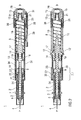
- Figure 1 shows two longitudinal sections in different section planes of an auto-injector 1, the different section planes approximately 90° rotated to each other.
- the auto-injector 1 comprises an elongate housing 2.
- a syringe 3, e.g. a Hypak syringe, with a hollow needle 4 is arranged in a proximal part of the auto-injector 1.
- a protective needle shield 5 is attached to the needle 4.
- a stopper 6 is arranged for sealing the syringe 3 distally and for displacing a liquid medicament M through the hollow needle 4.
- the syringe 3 is held in a tubular syringe carrier 7 and supported at its proximal end therein.
- a single compression spring 8 is arranged in a distal part of the auto-injector 1.
- a plunger 9 is arranged for forwarding the spring force of the compression spring 8.
- a retraction sleeve 10 is slidably arranged inside the housing 2 .
- the retraction sleeve 10 Before the injection is triggered as shown in figure 1 the retraction sleeve 10 is in a maximum proximal position and prevented from moving in distal direction D by means of stops 11 caught behind latches 12 in the housing 2.
- a distal end of the compression spring 8 bears against an end face 13 of the retraction sleeve 10. Due to the stops 11 and latches 12 the force of the compression spring 8 is thus reacted into the housing 2.
- the proximal end of the compression spring 8 bears against a decoupling member 14 arranged around the plunger 9.
- the retraction sleeve Distally from the end face 13 the retraction sleeve has two or more resilient arms 15 for holding a stud 16 and keeping it from being moved in proximal direction P.
- the stud 16 is arranged at the distal end of the plunger 9.
- the stud 16 and the resilient arms 15 have corresponding ramp features for pushing the resilient arms 15 apart in order to allow the stud 16 and the plunger 9 to move in proximal direction P.
- the decoupling member 14 comprises a thrust face 17 for bearing against a proximal end of the compression spring 8. Proximally from the thrust face 17 two or more resilient decoupling arms 18 are provided at the decoupling member 14, the decoupling arms 18 having inner ramped surfaces bearing against a first shoulder 19 in the plunger 9 in proximal direction P.
- the resilient decoupling arms 18 are supported by an inner wall of the retraction sleeve 10 in this situation so they cannot flex outward and slip past the first shoulder 19.
- a trigger button 20 is arranged at the distal end D of the auto-injector 1.
- the trigger button 20 may be pushed in proximal direction P in order to start an injection.
- the resilient arms 15 are caught between two or more retainers 21 arranged at the trigger button 20 so the resilient arms 15 cannot flex outward and the stud 16 although proximally biased by the compression spring 8 cannot slip through.
- the syringe carrier 7 is engaged for joint axial movement with a syringe holder 22 which is slidably arranged in the retraction sleeve 10.
- the syringe holder 22 is provided with two or more resilient syringe holder arms 23 arranged distally.
- the syringe holder arms 23 have a respective inclined surface for bearing against a second shoulder 24 in the plunger 9 arranged proximally from the first shoulder 19. In the initial position shown in figure 1 the syringe holder arms 23 are supported by an inner surface of the housing 2 so they cannot flex outward and the second shoulder 24 cannot slip through.
- a respective number of apertures are provided in the retraction sleeve 10.
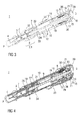
- Figure 6 shows details of the proximal end P of the auto-injector 1 as-delivered with a remover for the protective needle shield 5, the remover comprising a cap 25 screwed onto to the proximal end P of the auto-injector 1.
- the remover further comprises a resilient clip 26 with two or more barbs 27 extending through an orifice into the proximal end P of the auto-injector 1.
- the resilient clip 26 comprises a transversal front portion 26.1 pivoted in the cap 25.
- the barbs 27 respectively comprise a longitudinal leg 27.1 originating from the front portion 26.1 and ending in an essentially 90° offset hook 27.2 protruding inward from the longitudinal leg 27.1.
- the barbs 27 are inwardly biased.
- the resilient clip 26 is mounted to the cap 25 for joint axial movement with respect to a longitudinal axis of the auto-injector 1.
- the resilient clip 26 may rotate independently from the cap 25. This may be achieved by attaching the transversal front portion 26.1 with a hole onto a pin protruding inwardly from the cap 25 and deforming the pin to form a mushroom-shaped closing head 28 so as to prevent the resilient clip 26 from being removed while allowing some clearance for the resilient clip 26 to rotate.
- the cap 25 is screwed onto the proximal P end of the auto-injector 1 the barbs 27 are pushed down the protective needle shield 5 and snap into a circumferential notch arranged in the protective needle shield 5 or behind a shoulder thereof.
- the first step is to unscrew the cap 25.
- the barbs 27 pull the protective needle shield 5 off the syringe 3 in proximal direction P and through the orifice making the syringe 3 ready to be used.
- the resilient clip 26 is a sheet metal clip. Other materials, such as spring wire or plastic may also be applied.
- a safety button 29 is arranged laterally at the distal part of the housing 2.
- the safety button 29 serves for interlocking with the trigger button 20 in a manner to prevent the trigger button 20 from being inadvertently pushed without the safety button 29 being pushed first.
- the safety button 29 has to be pushed transversally with respect to the longitudinal axis against the force of a spring element 30 which is formed in the safety button 29.
- the safety button 29 is pivoted in the middle so pushing the proximal end of the safety button 29 inward pulls an interlock 31 at its proximal end obstructing the trigger button 20 outward so the trigger button 20 can be pushed.
- the second shoulder 24 pushes the syringe holder 22, syringe carrier 7 and syringe 3 forward while no load is exerted onto the stopper 6.
- the hollow needle 4 appears from the proximal end P and is inserted into an injection site, e.g. a patient's skin.
- the decoupling member 14 When the stopper 6 has nearly bottomed out in the syringe 3 (cf. figure 2 ) the decoupling member 14 has reached a position where its protrusions push against the latches 12 in a manner to decouple the retraction sleeve 10 from the housing 2, so the retraction sleeve 10 may slide in distal direction D.
- the compression spring 8 is no longer grounded with its distal end in the housing 2. Instead, as soon as the decoupling member 14 has bottomed out at a second abutment 33 the proximal end of the compression spring 8 gets grounded in the housing while the distal end is pulling the retraction sleeve 10 in distal direction D.
- the decoupling arms 18 reach an aperture 34 in the retraction sleeve 10 (see fig. 4 ) so they are no longer kept from being flexed outward.
- the decoupling arms 18 are thus pushed outward by the first shoulder 19 pushing against its ramped surfaces so the first shoulder 19 slips through in distal direction as soon as the decoupling member 14 has hit the second abutment 33.
- the syringe holder 22 is taken along in distal direction D by the retraction sleeve 10, e.g. by a front face 35.
- the syringe 3 and needle 4 are retracted into a safe position inside the housing 2, e.g. into the initial position.
- the plunger 9, no longer bearing against the decoupling arms 18 is pulled back too.
- a delay mechanism 36 is arranged (see figure 5 for details).
- the delay mechanism 36 comprises a circumferential outer wall 37 with a back collar 38 attached to the housing 2 and a circumferential inner wall 39 with a front collar 40 attached to the retraction sleeve 10.
- a cavity between the outer wall 37 and inner wall 39 is filled with a viscous fluid, such as silicon grease.
- a viscous fluid such as silicon grease.
- the inner wall 39 glides along the outer wall 37 wherein the back collar 38 and front collar 40 increasingly reduce the volume of the cavity.
- One or more holes (not shown) provided in a part of the delay mechanism 36 allow the viscous fluid to be pushed out of the cavity as the volume decreases. The force required to do this slows down the motion of the retraction sleeve 10.
- a circumferential shoulder 37.1 is arranged between two portions of the outer wall 37 with the two portions having different cross sections.
- the cavity is sealed by the front collar 40 only until the front collar 40 reaches the shoulder 37.1.
- the front collar 40 has travelled past the shoulder 37.1 the cavity is rendered untight so the motion of the retraction sleeve 10 continues undamped from this point.
- the retraction sleeve 10 is released by the decoupling member 14 from the housing 2 a certain amount of time or travel before the stopper 6 bottoms out in the syringe 3 so that the apertures 34 of the retraction sleeve 10 and the decoupling arms 18, which are now moving in opposite directions, meet after the stopper 6 and plunger 9 have stopped.
- the motion of the retraction sleeve 10 is slowed down by the delay mechanism 36. Due to a gap 41 between the front face 35 and the syringe holder 22 the retraction sleeve 10 is not yet dragging the syringe back in distal direction D.
- the plunger 9 is still pushing against the stopper 6 and expelling residual medicament M.
- the cap 25 and the delay mechanism 36 are not restricted to be used with the auto-injector 1 shown in the embodiments. Instead the cap 25 may be combined with any kind of auto-injector with the needle hidden in the housing prior to an injection.
- the delay mechanism 36 may be combined with any kind of auto-injector for ensuring full delivery of the syringe's contents and reliable triggering of the retraction, irrespective of the spring means or driving means used in the respective auto-injector.
- the housing 2 may have at least one viewing window for inspecting the syringe 3.
- the auto-injector 1 may preferably be used for delivering one of an analgetic, an anticoagulant, insulin, an insulin derivate, heparin, Lovenox, a vaccine, a growth hormone, a peptide hormone, a proteine, antibodies and complex carbohydrates.
- the delay mechanism 36 is not restricted to use with auto-injectors. It may be likewise used with other mechanical equipment.
- the aforementioned arrangement for coupling the plunger (9) to either, the syringe (3) or the stopper (6), may be applied in any auto-injector having a plunger for forwarding a force of a drive means to a syringe with a stopper.
- the primary advantage of this arrangement ensures the load from the drive means is not transferred directly to the stopper until the needle is inserted in the patient, thus avoiding a wet injection.
- the arrangement comprises the syringe holder (22) and associated syringe holder arms (23), a shoulder (e.g.
- the spring means or other drive means the ability to retract the syringe or to forward a needle shroud after injection and other features described herein are not required for the prevention of a wet injection.
Landscapes
- Health & Medical Sciences (AREA)
- Engineering & Computer Science (AREA)
- Heart & Thoracic Surgery (AREA)
- Vascular Medicine (AREA)
- Anesthesiology (AREA)
- Biomedical Technology (AREA)
- Hematology (AREA)
- Life Sciences & Earth Sciences (AREA)
- Animal Behavior & Ethology (AREA)
- General Health & Medical Sciences (AREA)
- Public Health (AREA)
- Veterinary Medicine (AREA)
- Environmental & Geological Engineering (AREA)
- Infusion, Injection, And Reservoir Apparatuses (AREA)
Priority Applications (1)
| Application Number | Priority Date | Filing Date | Title |
|---|---|---|---|
| EP10154006A EP2361648A1 (de) | 2010-02-18 | 2010-02-18 | Entfernung eines schützenden Nadelschirms |
Applications Claiming Priority (1)
| Application Number | Priority Date | Filing Date | Title |
|---|---|---|---|
| EP10154006A EP2361648A1 (de) | 2010-02-18 | 2010-02-18 | Entfernung eines schützenden Nadelschirms |
Publications (1)
| Publication Number | Publication Date |
|---|---|
| EP2361648A1 true EP2361648A1 (de) | 2011-08-31 |
Family
ID=42289650
Family Applications (1)
| Application Number | Title | Priority Date | Filing Date |
|---|---|---|---|
| EP10154006A Ceased EP2361648A1 (de) | 2010-02-18 | 2010-02-18 | Entfernung eines schützenden Nadelschirms |
Country Status (1)
| Country | Link |
|---|---|
| EP (1) | EP2361648A1 (de) |
Cited By (52)
| Publication number | Priority date | Publication date | Assignee | Title |
|---|---|---|---|---|
| WO2012103140A1 (en) * | 2011-01-24 | 2012-08-02 | Abbott Biotechnology Ltd | Removal of needle shields from syringes and automatic injection devices |
| WO2012085585A3 (en) * | 2010-12-22 | 2012-08-23 | Owen Mumford Limited | Autoinjectors |
| US8668670B2 (en) | 2004-06-23 | 2014-03-11 | Abbvie Biotechnology Ltd | Automatic injection devices |
| US8679061B2 (en) | 2006-06-30 | 2014-03-25 | Abbvie Biotechnology Ltd | Automatic injection device |
| DE102013112654A1 (de) | 2013-11-15 | 2015-05-21 | Gerresheimer Regensburg Gmbh | Spritze zur Injektion von flüssigen Substanzen |
| EP2886144A1 (de) * | 2013-12-20 | 2015-06-24 | Sanofi-Aventis Deutschland GmbH | Wirkstofffreisetzungsvorrichtung |
| CN104771814A (zh) * | 2015-04-28 | 2015-07-15 | 苏州施莱医疗器械有限公司 | 一次性安全型胰岛素注射针头 |
| CN104771815A (zh) * | 2015-04-28 | 2015-07-15 | 苏州施莱医疗器械有限公司 | 带针尖保护的胰岛素注射针头 |
| CN105939747A (zh) * | 2014-02-04 | 2016-09-14 | 赛诺菲-安万特德国有限公司 | 鞘移除机构 |
| WO2016193353A1 (en) * | 2015-06-03 | 2016-12-08 | Sanofi-Aventis Deutschland Gmbh | Grasper for a needle sheath, cap, autoinjector and method of producing a grasper |
| EP3117854A1 (de) * | 2015-07-15 | 2017-01-18 | Sanofi-Aventis Deutschland GmbH | Arzneimittelabgabevorrichtung mit mechanismus zum steuern einer nadelschutzkappe und aktivieren der vorrichtung |
| KR20170048508A (ko) * | 2014-09-01 | 2017-05-08 | 케어베이 유럽 리미티드 | 약물 전달 장치용 신호 지연 어셈블리 |
| US9878102B2 (en) | 2011-01-24 | 2018-01-30 | Abbvie Biotechnology Ltd. | Automatic injection devices having overmolded gripping surfaces |
| CN109310823A (zh) * | 2016-06-03 | 2019-02-05 | 艾斯曲尔医疗公司 | 药剂输送装置 |
| EP3474928A1 (de) | 2016-06-22 | 2019-05-01 | Antares Pharma, Inc. | Nadelschutzentferner |
| WO2019175665A3 (en) * | 2018-03-13 | 2019-11-07 | Mylan Uk Healthcare Ltd. | Devices for injecting medicaments and methods of use |
| CN110865681A (zh) * | 2019-12-16 | 2020-03-06 | 上海科聚精密塑料有限公司 | 一种用于安装电器旋钮的伸缩杆 |
| TWI689328B (zh) * | 2017-11-07 | 2020-04-01 | 瑞士商瑞健醫療股份有限公司 | 針遮蔽件移除器和包含有該針遮蔽件移除器的藥物輸送裝置 |
| US10806867B2 (en) | 2011-01-24 | 2020-10-20 | E3D Agricultural Cooperative Association Ltd. | Injector |
| WO2020245206A1 (en) * | 2019-06-04 | 2020-12-10 | Sanofi | Apparatus for removing a needle shield |
| USD948715S1 (en) | 2020-11-06 | 2022-04-12 | West Pharmaceutical Services, Inc. | Injection needle shield puller |
| US11311674B2 (en) | 2016-01-21 | 2022-04-26 | West Pharma. Services IL, Ltd. | Medicament delivery device comprising a visual indicator |
| US11318254B2 (en) | 2015-10-09 | 2022-05-03 | West Pharma. Services IL, Ltd. | Injector needle cap remover |
| US11338090B2 (en) | 2016-08-01 | 2022-05-24 | West Pharma. Services IL, Ltd. | Anti-rotation cartridge pin |
| US11364337B2 (en) | 2016-01-21 | 2022-06-21 | West Pharma. Services IL, Ltd. | Force containment in an automatic injector |
| US11389597B2 (en) | 2016-03-16 | 2022-07-19 | West Pharma. Services IL, Ltd. | Staged telescopic screw assembly having different visual indicators |
| USD958330S1 (en) | 2018-12-21 | 2022-07-19 | Janssen Pharmaceuticals, Inc. | Injection device accessory |
| US11446446B2 (en) | 2018-12-21 | 2022-09-20 | Janssen Pharmaceuticals, Inc. | Accessory for an injection device including a grip for a needle cap |
| US11504481B2 (en) | 2007-10-02 | 2022-11-22 | West Pharma. Services IL, Ltd. | Anti-rotation feature for infusion pump cartridge |
| US11547802B2 (en) | 2015-10-09 | 2023-01-10 | West Pharma. Services IL, Ltd. | Angled syringe patch injector |
| US11602599B2 (en) | 2018-12-21 | 2023-03-14 | Janssen Pharmaceuticals, Inc. | Accessory for an injection device including a pivotable cover |
| USD985117S1 (en) | 2021-03-10 | 2023-05-02 | Amgen Inc. | Handheld drug delivery device |
| USD985119S1 (en) | 2021-03-30 | 2023-05-02 | Amgen Inc. | Handheld drug delivery device |
| USD985116S1 (en) | 2021-03-10 | 2023-05-02 | Amgen Inc. | Handheld drug delivery device |
| USD985118S1 (en) | 2021-03-10 | 2023-05-02 | Amgen Inc. | Handheld drug delivery device |
| US11672904B2 (en) | 2016-01-21 | 2023-06-13 | West Pharma. Services IL, Ltd. | Needle insertion and retraction mechanism |
| USD990668S1 (en) | 2020-11-05 | 2023-06-27 | Amgen Inc. | Handheld drug delivery device |
| USD992109S1 (en) | 2020-11-05 | 2023-07-11 | Amgen Inc. | Handheld drug delivery device |
| US11701475B2 (en) | 2018-12-21 | 2023-07-18 | Janssen Pharmaceuticals, Inc. | Accessory including a slot for a flange of an injection device |
| USD1001272S1 (en) | 2016-04-28 | 2023-10-10 | Amgen Inc. | Autoinjector with removable cap |
| USD1004078S1 (en) | 2019-09-30 | 2023-11-07 | Amgen Inc. | Handheld drug delivery device |
| US11819666B2 (en) | 2017-05-30 | 2023-11-21 | West Pharma. Services IL, Ltd. | Modular drive train for wearable injector |
| USD1010107S1 (en) | 2020-11-05 | 2024-01-02 | Amgen Inc. | Handheld drug delivery device |
| US11857767B2 (en) | 2017-12-22 | 2024-01-02 | West Pharma. Services IL, Ltd. | Injector usable with different dimension cartridges |
| US11931552B2 (en) | 2015-06-04 | 2024-03-19 | West Pharma Services Il, Ltd. | Cartridge insertion for drug delivery device |
| USD1030040S1 (en) | 2020-01-14 | 2024-06-04 | Amgen Inc. | Handheld drug delivery device |
| USD1030041S1 (en) | 2020-01-14 | 2024-06-04 | Amgen Inc. | Handheld drug delivery device |
| US12053622B2 (en) | 2015-06-18 | 2024-08-06 | Sanofi-Aventis Deutschland Gmbh | Cap assembly for covering a needle shield and method for assembling the cap assembly |
| WO2024188764A1 (en) * | 2023-03-14 | 2024-09-19 | Shl Medical Ag | Cap module for a drug delivery device, and drug delivery device |
| US12357767B2 (en) | 2016-08-01 | 2025-07-15 | West Pharma. Services IL, Ltd. | Partial door closure prevention spring |
| CN120550259A (zh) * | 2025-07-30 | 2025-08-29 | 苏州嘉树医疗科技有限公司 | 一次性注射笔 |
| USD1124318S1 (en) | 2025-01-07 | 2026-04-28 | Amgen Inc. | Handheld drug delivery device |
Citations (5)
| Publication number | Priority date | Publication date | Assignee | Title |
|---|---|---|---|---|
| US20020095120A1 (en) | 2000-08-29 | 2002-07-18 | Andre Larsen | Automatic injection device |
| US20070112310A1 (en) * | 2003-07-31 | 2007-05-17 | Sid Technologies Llc | Injecting apparatus |
| WO2009040603A1 (en) * | 2007-09-25 | 2009-04-02 | Becton Dickinson France | Autoinjector with deshielder comprising tamper evidence means |
| WO2009081103A1 (en) * | 2007-12-20 | 2009-07-02 | Ucb Pharma S.A. | Auto- injector with a syringe lock for locking the barrel coupling element and syringe coupled thereto in said retract position |
| WO2010007395A1 (en) * | 2008-07-18 | 2010-01-21 | Ucb Pharma S.A. | Systems for administering medication for rheumatoid arthritis patients |
-
2010
- 2010-02-18 EP EP10154006A patent/EP2361648A1/de not_active Ceased
Patent Citations (5)
| Publication number | Priority date | Publication date | Assignee | Title |
|---|---|---|---|---|
| US20020095120A1 (en) | 2000-08-29 | 2002-07-18 | Andre Larsen | Automatic injection device |
| US20070112310A1 (en) * | 2003-07-31 | 2007-05-17 | Sid Technologies Llc | Injecting apparatus |
| WO2009040603A1 (en) * | 2007-09-25 | 2009-04-02 | Becton Dickinson France | Autoinjector with deshielder comprising tamper evidence means |
| WO2009081103A1 (en) * | 2007-12-20 | 2009-07-02 | Ucb Pharma S.A. | Auto- injector with a syringe lock for locking the barrel coupling element and syringe coupled thereto in said retract position |
| WO2010007395A1 (en) * | 2008-07-18 | 2010-01-21 | Ucb Pharma S.A. | Systems for administering medication for rheumatoid arthritis patients |
Cited By (132)
| Publication number | Priority date | Publication date | Assignee | Title |
|---|---|---|---|---|
| US8668670B2 (en) | 2004-06-23 | 2014-03-11 | Abbvie Biotechnology Ltd | Automatic injection devices |
| US9764090B2 (en) | 2004-06-23 | 2017-09-19 | Abbvie Biotechnology Ltd | Relating to automatic injection devices |
| US9017287B2 (en) | 2004-06-23 | 2015-04-28 | Abbvie Biotechnology Ltd | Automatic injection devices |
| US9486584B2 (en) | 2006-06-30 | 2016-11-08 | Abbvie Biotechnology Ltd. | Automatic injection device |
| US8679061B2 (en) | 2006-06-30 | 2014-03-25 | Abbvie Biotechnology Ltd | Automatic injection device |
| US11504481B2 (en) | 2007-10-02 | 2022-11-22 | West Pharma. Services IL, Ltd. | Anti-rotation feature for infusion pump cartridge |
| US11590291B2 (en) | 2007-10-02 | 2023-02-28 | West Pharma. Services IL, Ltd. | External drug pump |
| WO2012085585A3 (en) * | 2010-12-22 | 2012-08-23 | Owen Mumford Limited | Autoinjectors |
| AU2015238907B2 (en) * | 2011-01-24 | 2017-12-21 | Abbvie Biotechnology Ltd | Removal of needle shields from syringes and automatic injection devices |
| AU2012209222B2 (en) * | 2011-01-24 | 2015-07-09 | Abbvie Biotechnology Ltd | Removal of needle shields from syringes and automatic injection devices |
| EP3473283A1 (de) * | 2011-01-24 | 2019-04-24 | AbbVie Biotechnology Ltd. | Entfernung eines nadelschutzes von spritzen und automatische injektionsvorrichtungen |
| US10022503B2 (en) | 2011-01-24 | 2018-07-17 | Abbvie Biotechnology Ltd | Removal of needle shield from syringes and automatic injection devices |
| US9339610B2 (en) | 2011-01-24 | 2016-05-17 | Abbvie Biotechnology Ltd | Removal of needle shield from syringes and automatic injection devices |
| WO2012103140A1 (en) * | 2011-01-24 | 2012-08-02 | Abbott Biotechnology Ltd | Removal of needle shields from syringes and automatic injection devices |
| AU2015238907B9 (en) * | 2011-01-24 | 2018-05-24 | Abbvie Biotechnology Ltd | Removal of needle shields from syringes and automatic injection devices |
| US12420029B2 (en) | 2011-01-24 | 2025-09-23 | E3D Agricultural Cooperative Association Ltd. | Injector |
| US8708968B2 (en) | 2011-01-24 | 2014-04-29 | Abbvie Biotechnology Ltd. | Removal of needle shields from syringes and automatic injection devices |
| US9878102B2 (en) | 2011-01-24 | 2018-01-30 | Abbvie Biotechnology Ltd. | Automatic injection devices having overmolded gripping surfaces |
| US11565048B2 (en) | 2011-01-24 | 2023-01-31 | Abbvie Biotechnology Ltd. | Automatic injection devices having overmolded gripping surfaces |
| US10806867B2 (en) | 2011-01-24 | 2020-10-20 | E3D Agricultural Cooperative Association Ltd. | Injector |
| DE102013112654A1 (de) | 2013-11-15 | 2015-05-21 | Gerresheimer Regensburg Gmbh | Spritze zur Injektion von flüssigen Substanzen |
| EP2886144A1 (de) * | 2013-12-20 | 2015-06-24 | Sanofi-Aventis Deutschland GmbH | Wirkstofffreisetzungsvorrichtung |
| WO2015091850A1 (en) * | 2013-12-20 | 2015-06-25 | Sanofi-Aventis Deutschland Gmbh | Drug delivery device |
| CN105939747A (zh) * | 2014-02-04 | 2016-09-14 | 赛诺菲-安万特德国有限公司 | 鞘移除机构 |
| CN105939747B (zh) * | 2014-02-04 | 2019-12-31 | 赛诺菲-安万特德国有限公司 | 鞘移除机构 |
| WO2016034407A3 (en) * | 2014-09-01 | 2017-07-27 | Carebay Europe Ltd | Medicament delivery device with delivery finish signal delay |
| CN107530495A (zh) * | 2014-09-01 | 2018-01-02 | 卡贝欧洲有限公司 | 用于药剂输送装置的信号延迟组件 |
| KR20170048508A (ko) * | 2014-09-01 | 2017-05-08 | 케어베이 유럽 리미티드 | 약물 전달 장치용 신호 지연 어셈블리 |
| CN107530495B (zh) * | 2014-09-01 | 2020-10-09 | 艾斯曲尔医疗公司 | 用于药剂输送装置的信号延迟组件 |
| US10384009B2 (en) | 2014-09-01 | 2019-08-20 | Shl Medical Ag | Signal delaying assembly for a medicament delivery device |
| CN104771814B (zh) * | 2015-04-28 | 2017-11-21 | 苏州施莱医疗器械有限公司 | 一次性安全型胰岛素注射针头 |
| WO2016173367A1 (zh) * | 2015-04-28 | 2016-11-03 | 苏州施莱医疗器械有限公司 | 一次性安全型胰岛素注射针头 |
| WO2016173384A1 (zh) * | 2015-04-28 | 2016-11-03 | 苏州施莱医疗器械有限公司 | 带针尖保护的胰岛素注射针头 |
| CN104771815A (zh) * | 2015-04-28 | 2015-07-15 | 苏州施莱医疗器械有限公司 | 带针尖保护的胰岛素注射针头 |
| CN104771814A (zh) * | 2015-04-28 | 2015-07-15 | 苏州施莱医疗器械有限公司 | 一次性安全型胰岛素注射针头 |
| RU2720160C2 (ru) * | 2015-06-03 | 2020-04-24 | Санофи-Авентис Дойчланд Гмбх | Зажим для колпачка для иглы, крышка, автоматическое инъекционное устройство и способ изготовления зажима |
| US12357770B2 (en) | 2015-06-03 | 2025-07-15 | Sanofi-Aventis Deutschland Gmbh | Grasper for a needle sheath, cap, autoinjector and method of producing a grasper |
| IL256006A (en) * | 2015-06-03 | 2018-01-31 | Sanofi Aventis Deutschland | Grasper for a needle sheath, cap, autoinjector and method of producing a grasper |
| US11045610B2 (en) | 2015-06-03 | 2021-06-29 | Sanofi-Aventis Deutschland Gmbh | Grasper for a needle sheath, cap, autoinjector and method of producing a grasper |
| JP2018520738A (ja) * | 2015-06-03 | 2018-08-02 | サノフィ−アベンティス・ドイチュラント・ゲゼルシャフト・ミット・ベシュレンクテル・ハフツング | ニードルシースのための把持具、キャップ、自動注射器および把持具を生産する方法 |
| WO2016193353A1 (en) * | 2015-06-03 | 2016-12-08 | Sanofi-Aventis Deutschland Gmbh | Grasper for a needle sheath, cap, autoinjector and method of producing a grasper |
| US20210338940A1 (en) * | 2015-06-03 | 2021-11-04 | Sanofi Aventis Deutschland Gmbh | Grasper for a needle sheath, cap, autoinjector and method of producing a grasper |
| IL256006B (en) * | 2015-06-03 | 2021-12-01 | Sanofi Aventis Deutschland | Needle sheath gripper, automatic injector and method of making gripper |
| CN107708770A (zh) * | 2015-06-03 | 2018-02-16 | 赛诺菲-安万特德国有限公司 | 用于针鞘的抓持器、帽、自动注射器和制造抓持器的方法 |
| KR20180015677A (ko) | 2015-06-03 | 2018-02-13 | 사노피-아벤티스 도이칠란트 게엠베하 | 주사바늘 집을 위한 파지기, 캡, 자동 주사기, 및 파지기의 제조 방법 |
| AU2016269705B2 (en) * | 2015-06-03 | 2020-10-22 | Sanofi-Aventis Deutschland Gmbh | Grasper for a needle sheath, cap, autoinjector and method of producing a grasper |
| US11931552B2 (en) | 2015-06-04 | 2024-03-19 | West Pharma Services Il, Ltd. | Cartridge insertion for drug delivery device |
| US12053622B2 (en) | 2015-06-18 | 2024-08-06 | Sanofi-Aventis Deutschland Gmbh | Cap assembly for covering a needle shield and method for assembling the cap assembly |
| CN107847683B (zh) * | 2015-07-15 | 2020-12-04 | 赛诺菲-安万特德国有限公司 | 具有保护性针盖控制和装置启动构件的药物输送装置 |
| EP3117854A1 (de) * | 2015-07-15 | 2017-01-18 | Sanofi-Aventis Deutschland GmbH | Arzneimittelabgabevorrichtung mit mechanismus zum steuern einer nadelschutzkappe und aktivieren der vorrichtung |
| US10814071B2 (en) | 2015-07-15 | 2020-10-27 | Sanofi-Aventis Deutschland Gmbh | Drug delivery device with protective needle cap control and device activation mechanism |
| CN107847683A (zh) * | 2015-07-15 | 2018-03-27 | 赛诺菲-安万特德国有限公司 | 具有保护性针盖控制和装置启动构件的药物输送装置 |
| WO2017009360A1 (en) * | 2015-07-15 | 2017-01-19 | Sanofi-Aventis Deutschland Gmbh | Drug delivery device with protective needle cap control and device activation mechanism |
| US11547802B2 (en) | 2015-10-09 | 2023-01-10 | West Pharma. Services IL, Ltd. | Angled syringe patch injector |
| US12208246B2 (en) | 2015-10-09 | 2025-01-28 | West Pharma. Services IL, Ltd. | Bent fluid path add on to a prefilled fluid reservoir |
| US11724034B2 (en) | 2015-10-09 | 2023-08-15 | West Pharma. Services, IL, Ltd. | Injector system |
| US12138429B2 (en) | 2015-10-09 | 2024-11-12 | West Pharma. Services IL, Ltd. | Angled syringe patch injector |
| US11759573B2 (en) | 2015-10-09 | 2023-09-19 | West Pharma. Services, IL, Ltd. | Bent fluid path add on to a prefilled reservoir |
| US11318254B2 (en) | 2015-10-09 | 2022-05-03 | West Pharma. Services IL, Ltd. | Injector needle cap remover |
| US12036394B2 (en) | 2015-10-09 | 2024-07-16 | West Pharma. Services IL, Ltd. | Injector needle cap and/or liner remover |
| US12005237B2 (en) | 2016-01-21 | 2024-06-11 | West Pharma. Services IL, Ltd. | Medicament delivery device comprising a visual indicator |
| US11672904B2 (en) | 2016-01-21 | 2023-06-13 | West Pharma. Services IL, Ltd. | Needle insertion and retraction mechanism |
| US12427261B2 (en) | 2016-01-21 | 2025-09-30 | West Pharma. Services IL, Ltd. | Medicament delivery device comprising a visual indicator |
| US11311674B2 (en) | 2016-01-21 | 2022-04-26 | West Pharma. Services IL, Ltd. | Medicament delivery device comprising a visual indicator |
| US11364337B2 (en) | 2016-01-21 | 2022-06-21 | West Pharma. Services IL, Ltd. | Force containment in an automatic injector |
| US11389597B2 (en) | 2016-03-16 | 2022-07-19 | West Pharma. Services IL, Ltd. | Staged telescopic screw assembly having different visual indicators |
| USD1048382S1 (en) | 2016-04-28 | 2024-10-22 | Amgen Inc. | Autoinjector with removable cap |
| USD1065512S1 (en) | 2016-04-28 | 2025-03-04 | Amgen Inc. | Autoinjector with removable cap |
| USD1001272S1 (en) | 2016-04-28 | 2023-10-10 | Amgen Inc. | Autoinjector with removable cap |
| USD1023290S1 (en) | 2016-04-28 | 2024-04-16 | Amgen Inc. | Autoinjector with removable cap |
| US11986635B2 (en) | 2016-06-03 | 2024-05-21 | Shl Medical Ag | Medicament delivery device |
| US11191901B2 (en) | 2016-06-03 | 2021-12-07 | Shl Medical Ag | Medicament delivery device |
| CN109310823B (zh) * | 2016-06-03 | 2021-05-18 | 艾斯曲尔医疗公司 | 药剂输送装置 |
| US11273259B2 (en) | 2016-06-03 | 2022-03-15 | Shl Medical Ag | Medicament delivery device |
| CN109310823A (zh) * | 2016-06-03 | 2019-02-05 | 艾斯曲尔医疗公司 | 药剂输送装置 |
| US11097065B2 (en) | 2016-06-22 | 2021-08-24 | Antares Pharma, Inc. | Needle-shield remover |
| EP3474928A1 (de) | 2016-06-22 | 2019-05-01 | Antares Pharma, Inc. | Nadelschutzentferner |
| US12357767B2 (en) | 2016-08-01 | 2025-07-15 | West Pharma. Services IL, Ltd. | Partial door closure prevention spring |
| US11338090B2 (en) | 2016-08-01 | 2022-05-24 | West Pharma. Services IL, Ltd. | Anti-rotation cartridge pin |
| US11819666B2 (en) | 2017-05-30 | 2023-11-21 | West Pharma. Services IL, Ltd. | Modular drive train for wearable injector |
| US11850408B2 (en) | 2017-11-07 | 2023-12-26 | Shl Medical Ag | Needle shield remover and a medicament delivery device comprising the needle shield remover |
| TWI689328B (zh) * | 2017-11-07 | 2020-04-01 | 瑞士商瑞健醫療股份有限公司 | 針遮蔽件移除器和包含有該針遮蔽件移除器的藥物輸送裝置 |
| US11497858B2 (en) | 2017-11-07 | 2022-11-15 | Shl Medical Ag | Needle shield remover and a medicament delivery device comprising the needle shield remover |
| US11857767B2 (en) | 2017-12-22 | 2024-01-02 | West Pharma. Services IL, Ltd. | Injector usable with different dimension cartridges |
| US12023468B2 (en) | 2018-03-13 | 2024-07-02 | Mcdermott Laboratories Limited | Devices for injecting medicaments and methods of use |
| KR20200144544A (ko) * | 2018-03-13 | 2020-12-29 | 마일란 유케이 헬스케어 리미티드 | 약물 주입용 장치 및 그 이용 방법 |
| IL277150B2 (en) * | 2018-03-13 | 2026-01-01 | Mylan Uk Healthcare Ltd | Drug injection devices and methods of using them |
| US11793938B2 (en) | 2018-03-13 | 2023-10-24 | Mcdermott Laboratories Limited | Devices for injecting medicaments and methods of use |
| WO2019175665A3 (en) * | 2018-03-13 | 2019-11-07 | Mylan Uk Healthcare Ltd. | Devices for injecting medicaments and methods of use |
| IL277150B1 (en) * | 2018-03-13 | 2025-09-01 | Mylan Uk Healthcare Ltd | Drug injection devices and methods of using them |
| JP7702254B2 (ja) | 2018-03-13 | 2025-07-03 | マクダーモット ラボラトリーズ リミテッド | 薬剤を注入するための装置および使用方法 |
| US12329934B2 (en) | 2018-03-13 | 2025-06-17 | Mcdermott Laboratories Limited | Devices for injecting medicaments and methods of use |
| CN112312945A (zh) * | 2018-03-13 | 2021-02-02 | 迈兰英国医疗保健有限公司 | 用于注射药物的装置及使用方法 |
| JP2021518795A (ja) * | 2018-03-13 | 2021-08-05 | ミラン ユーケー ヘルスケア リミテッド | 薬剤を注入するための装置および使用方法 |
| CN112312945B (zh) * | 2018-03-13 | 2023-03-10 | 迈兰英国医疗保健有限公司 | 用于注射药物的装置及使用方法 |
| US11446446B2 (en) | 2018-12-21 | 2022-09-20 | Janssen Pharmaceuticals, Inc. | Accessory for an injection device including a grip for a needle cap |
| US11602599B2 (en) | 2018-12-21 | 2023-03-14 | Janssen Pharmaceuticals, Inc. | Accessory for an injection device including a pivotable cover |
| US11701475B2 (en) | 2018-12-21 | 2023-07-18 | Janssen Pharmaceuticals, Inc. | Accessory including a slot for a flange of an injection device |
| USD958330S1 (en) | 2018-12-21 | 2022-07-19 | Janssen Pharmaceuticals, Inc. | Injection device accessory |
| CN113950344B (zh) * | 2019-06-04 | 2024-11-05 | 赛诺菲 | 用于移除针护罩的设备 |
| JP2022535101A (ja) * | 2019-06-04 | 2022-08-04 | サノフイ | ニードルシールドを取り外すための装置 |
| CN113950344A (zh) * | 2019-06-04 | 2022-01-18 | 赛诺菲 | 用于移除针护罩的设备 |
| US12390602B2 (en) | 2019-06-04 | 2025-08-19 | Sanofi | Apparatus for removing a needle shield |
| WO2020245206A1 (en) * | 2019-06-04 | 2020-12-10 | Sanofi | Apparatus for removing a needle shield |
| USD1004078S1 (en) | 2019-09-30 | 2023-11-07 | Amgen Inc. | Handheld drug delivery device |
| USD1010811S1 (en) | 2019-09-30 | 2024-01-09 | Amgen Inc. | Handheld drug delivery device |
| CN110865681A (zh) * | 2019-12-16 | 2020-03-06 | 上海科聚精密塑料有限公司 | 一种用于安装电器旋钮的伸缩杆 |
| USD1030040S1 (en) | 2020-01-14 | 2024-06-04 | Amgen Inc. | Handheld drug delivery device |
| USD1030041S1 (en) | 2020-01-14 | 2024-06-04 | Amgen Inc. | Handheld drug delivery device |
| USD1083087S1 (en) | 2020-01-14 | 2025-07-08 | Amgen Inc. | Handheld drug delivery device |
| USD1084306S1 (en) | 2020-01-14 | 2025-07-15 | Amgen Inc. | Handheld drug delivery device |
| USD990668S1 (en) | 2020-11-05 | 2023-06-27 | Amgen Inc. | Handheld drug delivery device |
| USD1072240S1 (en) | 2020-11-05 | 2025-04-22 | Amgen Inc. | Handheld drug delivery device |
| USD1071163S1 (en) | 2020-11-05 | 2025-04-15 | Amgen Inc. | Handheld drug delivery device |
| USD1010107S1 (en) | 2020-11-05 | 2024-01-02 | Amgen Inc. | Handheld drug delivery device |
| USD992109S1 (en) | 2020-11-05 | 2023-07-11 | Amgen Inc. | Handheld drug delivery device |
| USD948715S1 (en) | 2020-11-06 | 2022-04-12 | West Pharmaceutical Services, Inc. | Injection needle shield puller |
| USD1097129S1 (en) | 2021-03-10 | 2025-10-07 | Amgen Inc. | Handheld drug delivery device |
| USD1073061S1 (en) | 2021-03-10 | 2025-04-29 | Amgen Inc. | Handheld drug delivery device |
| USD1071156S1 (en) | 2021-03-10 | 2025-04-15 | Amgen Inc. | Handheld drug delivery device |
| USD985118S1 (en) | 2021-03-10 | 2023-05-02 | Amgen Inc. | Handheld drug delivery device |
| USD1123151S1 (en) | 2021-03-10 | 2026-04-21 | Amgen Inc. | Handheld drug delivery device |
| USD985116S1 (en) | 2021-03-10 | 2023-05-02 | Amgen Inc. | Handheld drug delivery device |
| USD985117S1 (en) | 2021-03-10 | 2023-05-02 | Amgen Inc. | Handheld drug delivery device |
| USD1106445S1 (en) | 2021-03-10 | 2025-12-16 | Amgen Inc. | Handheld drug delivery device |
| USD1071160S1 (en) | 2021-03-30 | 2025-04-15 | Amgen Inc. | Handheld drug delivery device |
| USD1095819S1 (en) | 2021-03-30 | 2025-09-30 | Amgen Inc. | Handheld drug delivery device |
| USD985119S1 (en) | 2021-03-30 | 2023-05-02 | Amgen Inc. | Handheld drug delivery device |
| WO2024188764A1 (en) * | 2023-03-14 | 2024-09-19 | Shl Medical Ag | Cap module for a drug delivery device, and drug delivery device |
| USD1124318S1 (en) | 2025-01-07 | 2026-04-28 | Amgen Inc. | Handheld drug delivery device |
| CN120550259B (zh) * | 2025-07-30 | 2025-09-26 | 苏州嘉树医疗科技有限公司 | 一次性注射笔 |
| CN120550259A (zh) * | 2025-07-30 | 2025-08-29 | 苏州嘉树医疗科技有限公司 | 一次性注射笔 |
Similar Documents
| Publication | Publication Date | Title |
|---|---|---|
| EP2361648A1 (de) | Entfernung eines schützenden Nadelschirms | |
| US11504475B2 (en) | Auto-injector | |
| US9463282B2 (en) | Arrangement for coupling a plunger to either a syringe or a stopper | |
| EP2585138B1 (de) | Automatischer injektor | |
| US20130317446A1 (en) | Auto-Injector | |
| EP2399628A1 (de) | Automatischer Injektor | |
| EP2399630A1 (de) | Automatischer Injektor | |
| EP2399632A1 (de) | Automatischer Injektor mit einer einzigen Druckfeder und einem Querdruckknopf | |
| EP2441487A1 (de) | Automatischer Injektor |
Legal Events
| Date | Code | Title | Description |
|---|---|---|---|
| PUAI | Public reference made under article 153(3) epc to a published international application that has entered the european phase |
Free format text: ORIGINAL CODE: 0009012 |
|
| AK | Designated contracting states |
Kind code of ref document: A1 Designated state(s): AT BE BG CH CY CZ DE DK EE ES FI FR GB GR HR HU IE IS IT LI LT LU LV MC MK MT NL NO PL PT RO SE SI SK SM TR |
|
| AX | Request for extension of the european patent |
Extension state: AL BA RS |
|
| 17P | Request for examination filed |
Effective date: 20120229 |
|
| D17P | Request for examination filed (deleted) | ||
| STAA | Information on the status of an ep patent application or granted ep patent |
Free format text: STATUS: THE APPLICATION HAS BEEN REFUSED |
|
| 18R | Application refused |
Effective date: 20110930 |