EP2361673A2 - Dispositif - Google Patents
Dispositif Download PDFInfo
- Publication number
- EP2361673A2 EP2361673A2 EP11154905A EP11154905A EP2361673A2 EP 2361673 A2 EP2361673 A2 EP 2361673A2 EP 11154905 A EP11154905 A EP 11154905A EP 11154905 A EP11154905 A EP 11154905A EP 2361673 A2 EP2361673 A2 EP 2361673A2
- Authority
- EP
- European Patent Office
- Prior art keywords
- agitator
- passage
- connecting rod
- propeller
- drive motor
- Prior art date
- Legal status (The legal status is an assumption and is not a legal conclusion. Google has not performed a legal analysis and makes no representation as to the accuracy of the status listed.)
- Withdrawn
Links
- 239000000758 substrate Substances 0.000 claims abstract description 20
- 238000003756 stirring Methods 0.000 claims description 12
- 230000001681 protective effect Effects 0.000 claims 1
- 238000000855 fermentation Methods 0.000 description 2
- 230000004151 fermentation Effects 0.000 description 2
- 239000007789 gas Substances 0.000 description 2
- 238000002309 gasification Methods 0.000 description 2
- 238000009434 installation Methods 0.000 description 2
- 239000002028 Biomass Substances 0.000 description 1
- 229910000831 Steel Inorganic materials 0.000 description 1
- 230000005540 biological transmission Effects 0.000 description 1
- 238000010276 construction Methods 0.000 description 1
- 210000003608 fece Anatomy 0.000 description 1
- 238000003780 insertion Methods 0.000 description 1
- 230000037431 insertion Effects 0.000 description 1
- 239000010871 livestock manure Substances 0.000 description 1
- 238000004519 manufacturing process Methods 0.000 description 1
- 239000000463 material Substances 0.000 description 1
- 238000000034 method Methods 0.000 description 1
- 239000007787 solid Substances 0.000 description 1
- 239000010959 steel Substances 0.000 description 1
Images


Classifications
-
- A—HUMAN NECESSITIES
- A01—AGRICULTURE; FORESTRY; ANIMAL HUSBANDRY; HUNTING; TRAPPING; FISHING
- A01C—PLANTING; SOWING; FERTILISING
- A01C3/00—Treating manure; Manuring
- A01C3/02—Storage places for manure, e.g. cisterns for liquid manure; Installations for fermenting manure
- A01C3/026—Storage places for manure, e.g. cisterns for liquid manure; Installations for fermenting manure with mixing or agitating devices
-
- B—PERFORMING OPERATIONS; TRANSPORTING
- B01—PHYSICAL OR CHEMICAL PROCESSES OR APPARATUS IN GENERAL
- B01F—MIXING, e.g. DISSOLVING, EMULSIFYING OR DISPERSING
- B01F27/00—Mixers with rotary stirring devices in fixed receptacles; Kneaders
- B01F27/21—Mixers with rotary stirring devices in fixed receptacles; Kneaders characterised by their rotating shafts
- B01F27/2124—Shafts with adjustable length, e.g. telescopic shafts
-
- B—PERFORMING OPERATIONS; TRANSPORTING
- B01—PHYSICAL OR CHEMICAL PROCESSES OR APPARATUS IN GENERAL
- B01F—MIXING, e.g. DISSOLVING, EMULSIFYING OR DISPERSING
- B01F27/00—Mixers with rotary stirring devices in fixed receptacles; Kneaders
- B01F27/23—Mixers with rotary stirring devices in fixed receptacles; Kneaders characterised by the orientation or disposition of the rotor axis
- B01F27/231—Mixers with rotary stirring devices in fixed receptacles; Kneaders characterised by the orientation or disposition of the rotor axis with a variable orientation during mixing operation, e.g. with tiltable rotor axis
-
- B—PERFORMING OPERATIONS; TRANSPORTING
- B01—PHYSICAL OR CHEMICAL PROCESSES OR APPARATUS IN GENERAL
- B01F—MIXING, e.g. DISSOLVING, EMULSIFYING OR DISPERSING
- B01F33/00—Other mixers; Mixing plants; Combinations of mixers
- B01F33/86—Mixing heads comprising a driven stirrer
-
- B—PERFORMING OPERATIONS; TRANSPORTING
- B01—PHYSICAL OR CHEMICAL PROCESSES OR APPARATUS IN GENERAL
- B01F—MIXING, e.g. DISSOLVING, EMULSIFYING OR DISPERSING
- B01F35/00—Accessories for mixers; Auxiliary operations or auxiliary devices; Parts or details of general application
- B01F35/40—Mounting or supporting mixing devices or receptacles; Clamping or holding arrangements therefor
- B01F35/41—Mounting or supporting stirrer shafts or stirrer units on receptacles
- B01F35/411—Mounting or supporting stirrer shafts or stirrer units on receptacles by supporting only one extremity of the shaft
- B01F35/4113—Mounting or supporting stirrer shafts or stirrer units on receptacles by supporting only one extremity of the shaft at a side wall of the receptacle
-
- B—PERFORMING OPERATIONS; TRANSPORTING
- B01—PHYSICAL OR CHEMICAL PROCESSES OR APPARATUS IN GENERAL
- B01F—MIXING, e.g. DISSOLVING, EMULSIFYING OR DISPERSING
- B01F27/00—Mixers with rotary stirring devices in fixed receptacles; Kneaders
- B01F27/05—Stirrers
- B01F27/11—Stirrers characterised by the configuration of the stirrers
- B01F27/113—Propeller-shaped stirrers for producing an axial flow, e.g. shaped like a ship or aircraft propeller
-
- B—PERFORMING OPERATIONS; TRANSPORTING
- B01—PHYSICAL OR CHEMICAL PROCESSES OR APPARATUS IN GENERAL
- B01F—MIXING, e.g. DISSOLVING, EMULSIFYING OR DISPERSING
- B01F27/00—Mixers with rotary stirring devices in fixed receptacles; Kneaders
- B01F27/60—Mixers with rotary stirring devices in fixed receptacles; Kneaders with stirrers rotating about a horizontal or inclined axis
- B01F27/61—Mixers with rotary stirring devices in fixed receptacles; Kneaders with stirrers rotating about a horizontal or inclined axis about an inclined axis
Definitions
- the invention relates to a device for mixing the contents of substrate containers with a stirrer, consisting of a drive motor, a connecting rod and the end remote from the drive motor of the connecting rod a stirring propeller.
- stirrers of this type especially for mixing manure, but also just in biogas plants for mixing the material to be gasified known.
- the present invention is therefore based on the object to propose a device according to the preamble of the independent claim, which is also used in flat or covered with tarpaulin pools.
- This object is achieved in that a support means for receiving the weight of the agitator is provided.
- a dense and mobile implementation can be created, which nevertheless does not have to absorb the weight of the agitator. It is also conceivable that the cover is held by the implementation in a predetermined position. In addition, it is conceivable that flexible fermentation tanks can be created, protrudes through the walls of the Rüherwerk.
- Another very advantageous embodiment of the invention is also present when the agitator with respect to the support means and / or the implementation is pivotable and / or displaceable, and / or that the agitator is pivotable about a pivot point which lies at least substantially in the implementation.
- the carrying device is designed as a support arm, which may have an additional support strut against the ground.
- the support device has a length-adjustable strut for adjusting the vertical and or horizontal position of the articulation point of the agitator and / or the agitator.
- the agitator can be releasably connected to the support means and the implementation.
- the bushing has a liquid-tight and / or gas-tight seal towards the connecting rod.
- the substrate container can be sealed tight to the environment.
- the use of the agitator is also conceivable for substrate containers whose cover is raised in operation by the resulting gases and at least slightly inflated.
- the connecting rod is longitudinally displaceable and / or length-adjustable.
- Another very advantageous embodiment is also present when the propeller is associated with an at least partially encircling protection device.
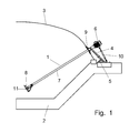
- FIG. 1 an agitator for mixing substrate in containers, especially in fermentation containers.
- a Gährungs employer is composed of a mostly sloping towards the middle sloping gutter 2 and a flexible cover 3.
- the cover 3 is connected to the gutter 2 in a gastight manner.
- Such containers are often used for the production of biogas from biomass.
- the substrate is introduced at one end of the container into the bottom channel 2 and at the other end the residues are discharged again after the gasification process.
- stirrers 1 are provided at the edge of the gutter. These are mounted on a support device 4, which is able to absorb the load of the respective agitator 1.
- the support means 4 may be formed as a strut, which may have an additional support 5, so that the support means 4 is able to absorb horizontal forces.
- the agitator 1 projects with its stirring propeller 8 into the substrate in the gutter 2.
- the connecting pipe 7 is guided through the cover 3 and sealed there with a bushing 9.
- the implementation 9 is arranged so that it is provided at least in the immediate vicinity of the support means 4. Thus, on the one hand movements of the cover 3 when moving the agitator 1 are at least largely avoided. On the other hand, the cover 3 is held by the passage, for example, when the substrate container is re-charged.
- the carrying device 4 engages directly on the passage 9.
- the fulcrum of the agitator 1 then lies almost exactly in the plane of the cover within the passage 9.
- a backup and support strut 10 which engages in the region of the lower end of the support means 4 and with its other end, for example on the drive motor. 6 to attack.
- the propeller 8 is driven by the drive motor 6 via a shaft, not shown.
- This shaft extends in the connecting tube 7 and is gas-tightly sealed with respect to this, for example with shaft seals, so that no gas is able to escape from the container via the connecting tube. In addition, it is also prevented that substrate penetrates into the connecting pipe 7.
- a protection 11 is provided which covers at least a portion of the propeller circumference and thus prevents the propeller can rest directly on the gutter 2 or that the propeller 8 is able to damage the cover 3, when it is lifted from the substrate , or when the cover 3 drops.
- the protection 11 may be formed as a circumferential ring which is fixed to the connecting pipe 7.
- the implementation 9 consists essentially of an inner ring 21, a support ring 22, are formed on the mounting tabs 23 which are connectable to the support means 4, a flexible seal 24 and an outer ring 25.
- the inner diameter of the inner ring 21 and the support ring 22 should be at least as large as the diameter of the guard 11 above the propeller 8, so that the stirring device 1 can be easily pulled out of the container, without the container should be emptied or entered, which then service work is very easy to carry out.
- the outer ring 25 is then simply unscrewed and removed together with the seal 24.
- the passage 9 can be connected, for example via tabs 23 and a bolt 31 1 with the support means 4.
- the bolt 31 may, for example, simultaneously engage in a further holding device 32 which is arranged on the connecting pipe 7 and defines the insertion position of the stirring device 1 and at the same time transmits the weight of the stirring device 1 to the carrying device 4.
- the support means 4 For installation of the stirring device 1 in existing container, the support means 4 is mounted and thus determines the position of the passage 9 on the cover 3. Then, a corresponding hole in the cover 9 are introduced. Then the inner ring 21 and the support ring 22 is mounted. About the tabs 23, the support ring 22 is already connected to the support means 4 and so the cover 3 are held in the later position. Further bushings 9 can now be mounted as well.
- stirring devices 1 Only then are the stirring devices 1 introduced through the openings of the passages 9 into the container.
- the stirring device 1 is with the Carrying device connected for example by bolts 31. Thereafter, the seal 24 and the outer ring 25 is connected to the inner ring 21 and the support ring 22 and so closed the cover again.
- the seal 24 may be formed, for example, as a rubber boot. But it is also conceivable that an at least partially flexible steel seal is provided.
Landscapes
- Chemical & Material Sciences (AREA)
- Chemical Kinetics & Catalysis (AREA)
- Life Sciences & Earth Sciences (AREA)
- Soil Sciences (AREA)
- Environmental Sciences (AREA)
- Mixers Of The Rotary Stirring Type (AREA)
- Accessories For Mixers (AREA)
Applications Claiming Priority (1)
| Application Number | Priority Date | Filing Date | Title |
|---|---|---|---|
| DE102010000489A DE102010000489B4 (de) | 2010-02-21 | 2010-02-21 | Vorrichtung |
Publications (2)
| Publication Number | Publication Date |
|---|---|
| EP2361673A2 true EP2361673A2 (fr) | 2011-08-31 |
| EP2361673A3 EP2361673A3 (fr) | 2013-01-02 |
Family
ID=44010122
Family Applications (1)
| Application Number | Title | Priority Date | Filing Date |
|---|---|---|---|
| EP11154905A Withdrawn EP2361673A3 (fr) | 2010-02-21 | 2011-02-17 | Dispositif |
Country Status (4)
| Country | Link |
|---|---|
| US (1) | US20110205833A1 (fr) |
| EP (1) | EP2361673A3 (fr) |
| BR (1) | BRPI1002134A2 (fr) |
| DE (1) | DE102010000489B4 (fr) |
Cited By (1)
| Publication number | Priority date | Publication date | Assignee | Title |
|---|---|---|---|---|
| DE102023122176A1 (de) | 2023-08-18 | 2025-02-20 | Thürwächter GmbH & Co. KG | Rührwerk mit Strömungssensor und Verfahren zum Betreiben des Rührwerks |
Families Citing this family (4)
| Publication number | Priority date | Publication date | Assignee | Title |
|---|---|---|---|---|
| SE534766C2 (sv) * | 2010-04-26 | 2011-12-13 | Itt Mfg Enterprises Inc | Genomföring för rötkammare |
| US8985841B2 (en) | 2013-01-15 | 2015-03-24 | The Maitland Company | Transportation of refinery solids waste |
| CN109337799B (zh) * | 2018-11-06 | 2023-08-25 | 胡小鹤 | 一种一体化的厌氧发酵装置 |
| CN114377583B (zh) * | 2022-03-24 | 2022-06-07 | 诸城市中裕机电设备有限公司 | 一种畜牧养殖用饲料混合装置 |
Family Cites Families (24)
| Publication number | Priority date | Publication date | Assignee | Title |
|---|---|---|---|---|
| US1703099A (en) * | 1923-07-31 | 1929-02-26 | Frederick L Craddock | Mixing device |
| US1693170A (en) * | 1925-03-30 | 1928-11-27 | Alsop Samuel | Mixer |
| US1817353A (en) * | 1929-08-28 | 1931-08-04 | Mixing Equipment Company Inc | Safety mixer |
| US2042511A (en) * | 1931-10-17 | 1936-06-02 | Mixing Equipment Company Inc | Safety mixer |
| US2116099A (en) * | 1936-09-04 | 1938-05-03 | Us Stoneware Co | Sealing, supporting, and cushioning assembly |
| US2209287A (en) * | 1938-04-07 | 1940-07-23 | Wilbur L Simpson | Apparatus for mixing |
| US2376722A (en) * | 1943-07-01 | 1945-05-22 | Abram I Podell | Mixing attachment |
| AT241276B (de) * | 1963-05-20 | 1965-07-12 | Bauer Roehren Pumpen | Misch- und Förderpumpe |
| US3223389A (en) * | 1964-02-10 | 1965-12-14 | Clyde S Simmonds | Paint mixer |
| US3425835A (en) * | 1964-03-30 | 1969-02-04 | Eastman Kodak Co | Method for dispersing non-aqueous solution in aqueous gelatin solutions using an aspirating agitator |
| GB1213501A (en) * | 1967-08-11 | 1970-11-25 | Wilhelm Grotz | Sewage agitator |
| DE2124313A1 (en) * | 1971-05-17 | 1972-11-30 | Kupka D | Side entry tank agitator - has angled shaft describing cone surface outline while agitator revolves |
| US4396291A (en) * | 1982-03-18 | 1983-08-02 | William Simmonds | Motor driven paint mixer |
| US4844843A (en) * | 1987-11-02 | 1989-07-04 | Rajendren Richard B | Waste water aerator having rotating compression blades |
| DE4124912A1 (de) * | 1991-07-26 | 1993-01-28 | Henkel Kgaa | Vorrichtung und verfahren zur pulverdosierung direkt aus dem verkaufsgebinde |
| US5226727A (en) * | 1991-09-30 | 1993-07-13 | Reichner Thomas W | Agitator/mixer |
| US6572261B1 (en) * | 2001-06-12 | 2003-06-03 | Walker Stainless Equipment Company | Horizontal agitator |
| EP1310292A1 (fr) * | 2001-11-13 | 2003-05-14 | Maschinenbau Peters S.P.R.L. | Dispositif mobile d'agitation |
| DE202004004101U1 (de) * | 2004-03-16 | 2004-07-29 | U.T.S. Umwelt-Technik-Süd GmbH | Fermenter einer Biogasanlage mit einer Rühreinrichtung |
| DE202005017638U1 (de) * | 2005-11-09 | 2006-04-06 | Envicon Klärtechnik Verwaltungsgesellschaft mbH | Führungsvorrichtung für ein Tauchrührwerk |
| DE202006013548U1 (de) * | 2006-09-01 | 2008-01-10 | Envicon Klärtechnik GmbH & Co. KG | Rühreinrichtung für einen gasdicht abgeschlossenen Behälter |
| DE102007022902A1 (de) * | 2007-05-14 | 2008-11-20 | Karl Buschmann Maschinenbau Gmbh | Fördersystem eines Gär- bzw. Faulbehälters |
| DE102007060608B4 (de) * | 2007-12-13 | 2013-03-14 | Thürwächter GmbH & Co. KG | Wanddurchführung |
| AT507028B1 (de) * | 2008-06-25 | 2012-07-15 | Sattler Ag | Erdbeckenfermenter |
-
2010
- 2010-02-21 DE DE102010000489A patent/DE102010000489B4/de not_active Expired - Fee Related
- 2010-06-04 BR BRPI1002134-5A patent/BRPI1002134A2/pt not_active IP Right Cessation
-
2011
- 2011-02-17 US US12/932,118 patent/US20110205833A1/en not_active Abandoned
- 2011-02-17 EP EP11154905A patent/EP2361673A3/fr not_active Withdrawn
Non-Patent Citations (1)
| Title |
|---|
| None |
Cited By (1)
| Publication number | Priority date | Publication date | Assignee | Title |
|---|---|---|---|---|
| DE102023122176A1 (de) | 2023-08-18 | 2025-02-20 | Thürwächter GmbH & Co. KG | Rührwerk mit Strömungssensor und Verfahren zum Betreiben des Rührwerks |
Also Published As
| Publication number | Publication date |
|---|---|
| DE102010000489A1 (de) | 2011-08-25 |
| EP2361673A3 (fr) | 2013-01-02 |
| US20110205833A1 (en) | 2011-08-25 |
| DE102010000489B4 (de) | 2012-07-26 |
| BRPI1002134A2 (pt) | 2011-11-01 |
Similar Documents
| Publication | Publication Date | Title |
|---|---|---|
| EP1992405B1 (fr) | Système de transport d'un récipient de fermentation ou de pourriture | |
| EP2389432B1 (fr) | Système de service pour installation de production de biogaz | |
| EP2270128B1 (fr) | Installation de biogaz et élement de regard pour une installation de biogaz | |
| EP2878365B1 (fr) | Agitateur pour un digesteur à biogaz | |
| DE202004004101U1 (de) | Fermenter einer Biogasanlage mit einer Rühreinrichtung | |
| EP2361673A2 (fr) | Dispositif | |
| DE102007005069A1 (de) | Biogasanlage | |
| DE102018000927A1 (de) | Biogasanlagen-Fermenterbehälter, Serviceeinrichtung zur Montage an einem Biogasanlagen-Fermenterbehälter sowie Verfahren zum Betreiben eines Biogasanlagen-Fermenterbehälters | |
| EP3898930A1 (fr) | Récipient ainsi que procédé pour le montage d'un malaxeur dans un récipient | |
| DE102010053242B4 (de) | Faulbehälter zur Erzeugung von Biogas | |
| DE202006013772U1 (de) | Anlage zur Erzeugung von Biogas | |
| EP2914709B1 (fr) | Fermenteur d'une installation de biogaz | |
| EP2513285B1 (fr) | Récipient d'une installation de biogaz et procédé pour prélever un composant du récipient | |
| DE102011114793A1 (de) | Verfahren und Anlage zur Herstellung von Biogassubstrat in Anmaischbehältern | |
| EP0127769B1 (fr) | Installation comprenant des récipients en prélarts synthétiques pour la fermentation progressive (aérobique et anaérobique) de fumiers d'animaux et de déchets agro-alimentaires | |
| DE202007018863U1 (de) | Gär- bzw. Faulbehälter | |
| EP2826549B1 (fr) | Dispositif de mélange du contenu de récipients de substrats | |
| WO2019029913A1 (fr) | Dispositif de mélange et procédé pour faire fonctionner un dispositif de mélange | |
| DE20110792U1 (de) | Biogasanlage | |
| DE102011081431A1 (de) | Gär- oder Faulbehälter mit Einbauschacht sowie Montageeinheit und Verfahren zur Montage und Demontage eines Rührwerks | |
| DE102023130175A1 (de) | Biogasanlagen-Fermenterbehälter sowie Verfahren zum Betrieb | |
| DE102023130174A1 (de) | Biogasanlagen-Fermenterbehälter sowie Verfahren zum Betrieb | |
| DE102023130176A1 (de) | Biogasanlagen-Fermenterbehälter sowie Verfahren zum Betrieb | |
| WO2015135616A1 (fr) | Dispositif de fermentation de la biomasse pour produire du gaz | |
| DE202012012723U1 (de) | Biogasanlage |
Legal Events
| Date | Code | Title | Description |
|---|---|---|---|
| PUAI | Public reference made under article 153(3) epc to a published international application that has entered the european phase |
Free format text: ORIGINAL CODE: 0009012 |
|
| AK | Designated contracting states |
Kind code of ref document: A2 Designated state(s): AL AT BE BG CH CY CZ DE DK EE ES FI FR GB GR HR HU IE IS IT LI LT LU LV MC MK MT NL NO PL PT RO RS SE SI SK SM TR |
|
| AX | Request for extension of the european patent |
Extension state: BA ME |
|
| PUAL | Search report despatched |
Free format text: ORIGINAL CODE: 0009013 |
|
| AK | Designated contracting states |
Kind code of ref document: A3 Designated state(s): AL AT BE BG CH CY CZ DE DK EE ES FI FR GB GR HR HU IE IS IT LI LT LU LV MC MK MT NL NO PL PT RO RS SE SI SK SM TR |
|
| AX | Request for extension of the european patent |
Extension state: BA ME |
|
| RIC1 | Information provided on ipc code assigned before grant |
Ipc: A01C 3/02 20060101ALI20121126BHEP Ipc: B01F 15/00 20060101AFI20121126BHEP Ipc: B01F 7/00 20060101ALI20121126BHEP Ipc: F16M 11/00 20060101ALI20121126BHEP Ipc: C12M 1/107 20060101ALI20121126BHEP |
|
| 17P | Request for examination filed |
Effective date: 20130225 |
|
| 17Q | First examination report despatched |
Effective date: 20131105 |
|
| GRAP | Despatch of communication of intention to grant a patent |
Free format text: ORIGINAL CODE: EPIDOSNIGR1 |
|
| INTG | Intention to grant announced |
Effective date: 20151113 |
|
| STAA | Information on the status of an ep patent application or granted ep patent |
Free format text: STATUS: THE APPLICATION IS DEEMED TO BE WITHDRAWN |
|
| 18D | Application deemed to be withdrawn |
Effective date: 20160315 |