EP2361694A1 - Vorrichtung zur Behandlung von Gegenständen wie Obst und Gemüse, mit einem Reinigungswagen sowie Reinigungsverfahren - Google Patents
Vorrichtung zur Behandlung von Gegenständen wie Obst und Gemüse, mit einem Reinigungswagen sowie Reinigungsverfahren Download PDFInfo
- Publication number
- EP2361694A1 EP2361694A1 EP11155899A EP11155899A EP2361694A1 EP 2361694 A1 EP2361694 A1 EP 2361694A1 EP 11155899 A EP11155899 A EP 11155899A EP 11155899 A EP11155899 A EP 11155899A EP 2361694 A1 EP2361694 A1 EP 2361694A1
- Authority
- EP
- European Patent Office
- Prior art keywords
- cleaning
- carriage
- channel
- hydraulic
- cleaned
- Prior art date
- Legal status (The legal status is an assumption and is not a legal conclusion. Google has not performed a legal analysis and makes no representation as to the accuracy of the status listed.)
- Granted
Links
Images


Classifications
-
- B—PERFORMING OPERATIONS; TRANSPORTING
- B08—CLEANING
- B08B—CLEANING IN GENERAL; PREVENTION OF FOULING IN GENERAL
- B08B9/00—Cleaning hollow articles by methods or apparatus specially adapted thereto
- B08B9/02—Cleaning pipes or tubes or systems of pipes or tubes
- B08B9/027—Cleaning the internal surfaces; Removal of blockages
- B08B9/04—Cleaning the internal surfaces; Removal of blockages using cleaning devices introduced into and moved along the pipes
- B08B9/053—Cleaning the internal surfaces; Removal of blockages using cleaning devices introduced into and moved along the pipes moved along the pipes by a fluid, e.g. by fluid pressure or by suction
- B08B9/055—Cleaning the internal surfaces; Removal of blockages using cleaning devices introduced into and moved along the pipes moved along the pipes by a fluid, e.g. by fluid pressure or by suction the cleaning devices conforming to, or being conformable to, substantially the same cross-section of the pipes, e.g. pigs or moles
-
- B—PERFORMING OPERATIONS; TRANSPORTING
- B08—CLEANING
- B08B—CLEANING IN GENERAL; PREVENTION OF FOULING IN GENERAL
- B08B1/00—Cleaning by methods involving the use of tools
- B08B1/30—Cleaning by methods involving the use of tools by movement of cleaning members over a surface
-
- B—PERFORMING OPERATIONS; TRANSPORTING
- B65—CONVEYING; PACKING; STORING; HANDLING THIN OR FILAMENTARY MATERIAL
- B65G—TRANSPORT OR STORAGE DEVICES, e.g. CONVEYORS FOR LOADING OR TIPPING, SHOP CONVEYOR SYSTEMS OR PNEUMATIC TUBE CONVEYORS
- B65G51/00—Conveying articles through pipes or tubes by fluid flow or pressure; Conveying articles over a flat surface, e.g. the base of a trough, by jets located in the surface
- B65G51/01—Hydraulic transport of articles
Definitions
- the invention relates to a device for processing products such as fruits or vegetables comprising a plurality of hydraulic product transport channels, each channel extending between side walls, and means capable of producing a liquid flow parallel to the walls. sideways in each hydraulic channel. It is generally intended to solve the problem of cleaning each hydraulic channel of such a device, and extends to a method of cleaning such a device.
- Such a treatment device is for example, but not exclusively, a fruit or vegetable sorting unit according to predetermined selection criteria, comprising a continuous feed device with products, at least one predetermined characteristics analysis station. products (for example by weighing, calibration, optical analysis, etc.) and a device capable of discharging the products upstream of a plurality of parallel hydraulic channels as a function of the result of the analysis of the products, so as to to group in each hydraulic channel the batch products having the same characteristics with respect to said selection criteria. The products thus grouped in each hydraulic channel can then be extracted from each hydraulic channel and packaged.
- US7159373 describes the general architecture of an example of such a processing device.
- Such a treatment device poses the general problem of cleaning the walls of each hydraulic channel, which must be carried out regularly.
- this cleaning is essentially done manually by scanning and / or brushing (with or without suction / filtration) walls by a human operator during the interruption phases of the device, for example at night.
- a cleaning operation although long, complex, and expensive, is preferred to the addition of an automatic cleaning robot that can unacceptably burden the cost, use and maintenance of a machine.
- an automatic cleaning robot that can unacceptably burden the cost, use and maintenance of a machine.
- It also imposes an interruption of the device, which is undesirable in certain applications for which the device must preferably be able to operate permanently.
- the invention therefore aims to solve these problems by proposing a treatment device provided with at least one automatic cleaning device capable of cleaning regularly - particularly as often as possible - the walls of each hydraulic channel in which it is driven in displacement, and which moreover is sufficiently simple and inexpensive to be compatible with an operation on an industrial scale, in particular on a fruit or vegetable sorting unit, and in particular is competitive with respect to a manual cleaning of each hydraulic channel.
- the invention also aims at providing a method of cleaning such a treatment device, this method having the same qualities, in particular being able to be automated.
- the invention extends to a cleaning method implemented in a treatment device according to the invention.
- the invention therefore also relates to a method of cleaning a product treatment device such as fruits or vegetables comprising a plurality of hydraulic channels, in which method a cleaning device is driven in displacement in at least one hydraulic channel thereof.
- a cleaning carriage is placed in a hydraulic channel, said channel cleaned, said cleaning carriage being guided in translation along the cleaned channel, and being provided with brushing members of the walls of the cleaned channel, then the cleaning carriage is translated into the cleaning position in the cleaned channel to clean the walls of said cleaned channel, and the cleaning carriage is transferred to another hydraulic channel for cleaning of the latter.
- the device for transferring a cleaning carriage of a device according to the invention may be the subject of different embodiments.
- this transfer device may or may not be fully integrated into the cleaning carriage itself.
- the hydraulic channels extending parallel to each other by joining two by two the transfer device comprises rails surmounting the upstream ends of the hydraulic channels and a guided transfer carriage and driven on these rails, this transfer carriage comprising fastening members of the cleaning carriage.
- the attachment members of the transfer carriage are adapted to cooperate with the cleaning carriage in the return position to suspend it.
- the motorized device can be actuated to move upwards the guiding members of the cleaning trolley with respect to the cleaned channel, these guiding members being carried by the trolley of cleaning, such that these guide members no longer cooperate with the cleaned channel and allow the movement of the cleaning carriage to another hydraulic channel.
- the brushing members serve at least partly guiding members.
- specific guide members, separate from the brushing members, for example rollers, are provided.
- the cleaning trolley may be driven in any suitable way in the cleaned channel, in particular by guiding and driving members carried by the cleaning trolley and resting on the side walls, for example motorized or non-motorized rollers and / or a training chain or other.
- the cleaning trolley comprises at least one hydraulic drive blade capable of extending into the stream of liquid circulating in the cleaned channel so as to drive the cleaning trolley in translation towards the trolley. downstream in the cleaned channel under the effect of the liquid stream.
- the cleaning carriage can be driven in displacement in the downstream cleaned channel only hydraulically, that is to say by the flow of the liquid flowing in at least one cleaned channel. Consequently, the means used for this training are simplified to the extreme, and have only a very small impact on the cost of manufacturing and using the device.
- the cleaning trolley may be provided with a single single plate extending transversely in the cleaned channel surmounted by the cleaning trolley guided by guide members such as rollers rolling on the side walls of the cleaned channel.
- the motorized device comprises at least one actuator - in particular a pneumatic or hydraulic cylinder or an electric motor - carried by the cleaning trolley supplied with energy - in particular with fluid under pressure or electricity - by a cord - in particular a pipe or cable - wound on a drum carried upstream of each cleaned channel, said drum being free to rotate in the direction of deployment of the cord and the movement of the cleaning carriage downstream in each channel cleaned, and coupled to a motor adapted to wind the cord on the drum and move the cleaning carriage upstream by pulling on the cord.
- actuator - in particular a pneumatic or hydraulic cylinder or an electric motor - carried by the cleaning trolley supplied with energy - in particular with fluid under pressure or electricity - by a cord - in particular a pipe or cable - wound on a drum carried upstream of each cleaned channel, said drum being free to rotate in the direction of deployment of the cord and the movement of the cleaning carriage downstream in each channel cleaned, and coupled to a motor adapted to wind the cord on the drum and move the cleaning carriage upstream by pulling on the cord.
- the power cord of the actuator of the cleaning carriage is bi-functional and is used to serve not only power supply of the actuator, but also of traction cable to bring the cleaning carriage into position upstream.
- a treatment device may comprise any other motorized device for driving the cleaning carriage in the initial upstream position, in particular a specific traction cable driven by a drum or the like.
- a treatment device according to the invention may comprise several cleaning carriages. Nevertheless, advantageously, a treatment device according to the invention comprises a single cleaning trolley, the transfer device being provided with a control automaton able to transfer the cleaning trolley successively from one hydraulic channel to another in order to to clean all the hydraulic channels
- a device is a device for sorting and bundling products, provided with at least one sorting unit arranged upstream of each hydraulic channel and adapted to discharge into each hydraulic channel sorted products. according to predetermined selection criteria
- the invention may, however, also be the subject of other applications for other types of processing devices.
- a cleaning trolley can be placed in a hydraulic channel after emptying the hydraulic channel, or when the hydraulic channel is not supplied with products. Nevertheless, it is an important advantage of a method according to the invention to allow the cleaning of a hydraulic channel even when the product treatment device is in operation.
- a cleaning trolley is placed in a hydraulic channel after reception by the latter of a predetermined quantity of products corresponding to a batch.
- the invention thus makes it possible to carry out the automatic cleaning of each hydraulic channel in operation, in an extremely simple, inexpensive way, and even without manual intervention by human operators.
- the invention also relates to a device and a method characterized in combination by all or some of the characteristics mentioned above or below.
- a processing device is an automatic fruit or vegetable sorting unit according to predetermined selection criteria for grouping the products in batches that can then be processed, in particular packaged and / or conditioned, homogenous and compatible with their subsequent use.
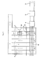
- Such a device comprises, in a manner known per se (see for example US 7159373 ) a plurality of hydraulic channels 11 parallel to each other, which are adjacent, each supplied by a liquid stream produced by a pumping station (not shown) and recycled in closed cycle. At least partial and continuous filtration of the liquid is generally provided.
- the automatic sorting unit comprises an input receptacle of the bulk products, a supply conveyor drawing the products of the input receptacle, at least one item 13, 14 for analyzing the products according to predetermined selection criteria.
- a sorting conveyor 15 capable of discharging the products after analysis upstream (with respect to the direction of circulation of the liquid) of one of the hydraulic channels 11, according to the results of the analysis carried out.
- the liquid is water and the products float in the liquid.
- the invention is nevertheless applicable to any other liquid, and to products carried by a stream of liquid without necessarily floating relative to the liquid.
- the hydraulic channels 11 are each formed of a bottom 16 in the form of a generally horizontal longitudinal strip (preferably having a slight slope downstream promoting the circulation of the liquid) and side walls 17 extending upwards on each side the bottom.
- the side walls 17 have a free upper horizontal rim 18 or parallel to the bottom, and forming a raceway for rollers 19 of a cleaning carriage 20.
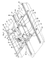
- the cleaning carriage 20 comprises a chassis 21, generally in the form of a frame, of width corresponding to that of a hydraulic channel 11 so as to be able to overcome and overlap the latter, by rolling on the upper edges 18 of the two side walls 17 of the hydraulic channel, said cleaned channel 11, surmounted by the carriage 20, thanks to the rollers 19 mounted freely rotating about horizontal axes transverse to the frame 21.
- each roller 19 is freely rotatably mounted at the end 23 of an arm 22, the other end 24 of which is integral in rotation with a transverse horizontal shaft rotatably mounted relative to the frame 21 by means of two bearings 26.
- the shaft 25 is rotated and held in angular position by means of at least one double-acting jack 27 mounted on the frame 21 and whose actuating rod 28 is articulated to a rod 29 integral in rotation with the tree 25.
- the arms 22 coupled to the same shaft 25, at each of its ends, are parallel to each other and can be placed either in the cleaning position in which the arms 22 are at least substantially horizontal so that the frame 21 is lowered into the cleaned channel 11, in the raised position, called the return position, in which the arms 22 are at least substantially vertical so that the frame 21 is raised above the cleaned channel 11.
- the carriage 20 comprises two parallel transverse shafts each carrying two articulated arms 22 and two rollers 19, which are controlled in position by two synchronized cylinders 27 (fed in parallel by the same source of pressure fluid) or by the same cylinder.
- the rollers 19 are of the shoulder type so as to lock the carriage 20 laterally with respect to the side walls 17.
- the carriage 20 also comprises members 30, 32 for brushing the walls 16, 17 of the cleaned channel 11.
- the carriage 20 carries a pair of bottom brushes and two pairs of side brushes 32.
- the bottom brushes are arranged to rub against the bottom 16 of the cleaned channel 11 when the carriage 20 is in the cleaning position.
- the two bottom brushes 30 are respectively fixed to the ends of an elastic blade 31 fastened by its middle part to the frame 21, the assembly being adapted so that the elastic blade 31 is deformed in elastic flexion when the carriage 20 is in position. cleaning position, the bottom brushes being applied with an elastic stress against the bottom 16.
- the side brushes 32 are arranged to rub against the side walls 17 of the cleaned channel 11 when the carriage 20 is in the cleaning position.
- the two side brushes 32 of the same pair are fixed respectively to the ends of an elastic blade 33 fixed by its median portion on the frame 21, the assembly being adapted so that the elastic blade 33 is deformed in elastic flexion when the carriage 20 is in the cleaning position, the side brushes 32 being applied with an elastic constraint against the corresponding lateral wall 17 facing each other.
- the carriage 20 also carries a hydraulic drive plate 34 whose dimensions correspond as closely as possible to the cross-section of the cleaned channel 11.
- the hydraulic drive plate extends transversely and is mounted relative to the frame 21 so as to block, in the cleaning position, the flow of the liquid flowing in the cleaned channel 11. Accordingly, in the cleaning position, the plate 34 receives on its upstream face 35 the pressure induced by the current of liquid in the cleaned channel 11, which has the effect of driving it, as well as the carriage 20 which it is secured, moving downstream in the cleaned channel 11.
- the hydraulic drive plate 34 is mounted at the downstream end of the carriage 20, so as to also be a barrier to the products possibly located downstream of the carriage 20 which are carried by the stream of liquid in the cleaned channel 11. In this way, the carriage 20 will not interfere with these products. In a variant, nothing prevents the fitting of a hydraulic drive plate rather than the upstream end of the carriage 20, which favors the efficiency of the hydraulic drive by the liquid flow. None prevents either to provide two hydraulic drive plates, one downstream, the other upstream.
- Each hydraulic drive plate is mounted relative to the frame 21 so as to extend into the liquid stream in the cleaning position for the hydraulic drive of the carriage 20, and so as to be entirely located outside the liquid stream in the return position, so as not to interfere with the latter, to allow the carriage 20 to return to the upstream end of the cleaned channel 11.
- the cylinders 27 carried by the frame 21 are supplied with pressurized fluid, for example compressed air if it is pneumatic cylinders, by means of a hose 36 wound on a drum 37 disposed upstream of the cleaned channel 11 , and which is automatically unwound during the cleaning phase as the carriage 20 moves downstream, and re-wound during the return phase of the carriage 20 to the upstream end.
- the drum 37 is coupled to a motor 38 which rotates it in one direction or the other.
- a voltage sensor 39 makes it possible to detect the voltage of the pipe 36. When the voltage in the pipe 36 is sufficient, as detected by the sensor 39, the motor 38 is controlled in the direction of flow of the pipe 36, so that the latter follows the movement of the carriage 20 downstream in the cleaning phase.
- the cylinders 27 are supplied with fluid under pressure in order to place the carriage 20 in the return position, then the motor 38 is controlled so as to wind the pipe 26 on the 37.
- the pipe 26 drives the carriage 20 in upstream movement, the rollers 19 rolling on the side walls 17.
- the length of the arms 22 is such that the carriage 20 is even entirely located above the upper edges 18 of the side walls 17. In this way, the carriage 20 offers no particular resistance to its displacement upstream. under the effect of traction by the pipe 26.
- the carriage 20 is entirely located outside the cleaned channel 11 in the return position makes it possible, in this position, to use the cleaned channel 11 to receive new products, without the risk of interfering with the cleaning carriage 20.
- the operations of cleaning and return of the carriage 20 can be integrated into the general operation of the processing device according to the invention without disturbing any of the phases and without reducing performance or productivity.
- a transfer device 40 is also provided for automatically moving the cleaning carriage 20 from one hydraulic channel 11 to the other, so that the cleaning management of a processing device according to the invention can be fully automated.
- this transfer device 40 comprises a transfer carriage 41 guided and driven on rails 42 extending above the upstream ends of the hydraulic channels 11, perpendicular to the hydraulic channels 11
- the rails 42 are parallel to the sorting conveyor 15 and may extend upstream or below or immediately downstream of the latter. It is sufficient to ensure that the transfer device 40 does not interfere with the operation of the sorting conveyor 15 and vice versa that the sorting conveyor 15 does not interfere with the operation of the transfer device 40.
- the rails 42 of the transfer device 40 extend immediately downstream of the sorting conveyor 15.
- the transfer carriage 41 carries the winding drum 37 of the pipe 36 and the motor 38 driving the drum 37.
- the drum 37 is itself supplied with fluid under pressure by a flexible pipe (not shown) which follows the movements of the carriage 41 on the rails 42 and is connected to the pipe 36.
- the transfer carriage 41 also carries rollers 43, preferably of the shoulder type, enabling the transfer carriage 41 to be guided and moved on the rails 42.
- the carriage 41 also carries a motor 44 for driving this carriage 41 of transfer on the rails 42, this motor 44 being coupled in rotation to a shaft 45 integral with a pair of rollers 43.
- the transfer carriage 41 also carries hooks 46 suspended from the transfer carriage 41, each hook 46 being articulated by its upper end to the transfer carriage 41 about an axis generally orthogonal to the longitudinal direction of the hydraulic channels 11.
- the end The bottom of the hooks 46 is adapted to hook onto the cleaning carriage 20, under a transverse bar of the latter, for example under the shafts 25 of the arms 22 carrying the rollers 19.
- the transfer carriage 41 advantageously comprises two pairs of hooks 46, each pair of hooks 46 being integral with the same shaft 48 and adapted to hook under one of the shafts 25 of the cleaning carriage 20, when the latter is in the return position and is driven upstream movement until coming under the transfer carriage 41.
- a double-acting jack 47 carried by the transfer carriage 41 makes it possible to drive the shaft 48 in rotation and to move each pair of hooks 46 between a hooking position where the hooks 46 are situated under the shaft 25, and a release position in which the cleaning carriage 20 is no longer suspended from the hooks 46 and vice versa.
- the transfer carriage 41 may comprise a single cylinder 47 controlling (via a suitable mechanism) the two pairs of hooks 46.
- the transfer carriage 41 comprises two jacks 47 fed in parallel, a jack 47 for each pair of hooks 46, so that the hooks 46 are controlled in a synchronized manner.
- the rails 42 are arranged at a sufficient height above the hydraulic channels to allow the passage of the cleaning carriage 20 under the rails 42 and therefore under the transfer carriage 41.
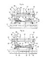
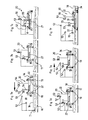
- the cylinders 27 can be actuated to return the arms 22 to the cleaning position. Nevertheless, the carriage 20 then remains suspended from the hooks 46 above the hydraulic channel 11 and does not descend to the cleaning position in the hydraulic channel 11 ( figure 4a ).
- the drive motor 44 of the transfer carriage 41 is then controlled to move the latter over another hydraulic channel 11 to be cleaned.
- the cylinders 27 are again actuated to replace the rollers 19 in contact with the edges 18 of the side walls 17 of the hydraulic channel 11 to be cleaned ( figure 4b ).
- the cylinder (s) 47 for controlling the hooks 46 is (are) actuated (s) in the release position ( figure 4c ), then the cylinders 27 are again actuated to place the arms 22 and the rollers 19 in the cleaning position ( figure 4d ). The cleaning carriage thus released is then driven downstream by the liquid stream and proceeds to the cleaning of the hydraulic channel 11.
- the device according to the invention also incorporates an appropriate control logic that can be embedded in all or part on the cleaning carriage 20 and / or on the transfer carriage 41 and / or incorporated in a fixed control unit.
- the control logic receives signals emitted by different sensors detecting the position and / or stroke of the cleaning carriage 20, the position and / or the travel of the transfer carriage 41, the state and / or stroke of the various motors and cylinders.
- the control logic is adapted and programmed to emit signals to control the appropriate movements of the various motors and cylinders.
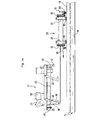
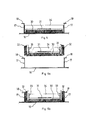
- FIGS 7a to 7f represent a second embodiment of a treatment device according to the invention in different stages of a cleaning process according to the invention.
- This second embodiment differs from the first in that the transfer device does not consist of a second carriage, but by motorized rollers 53 carried by the cleaning carriage 20 itself and cooperating with rails 52. extending above the upstream ends of the hydraulic channels 11, perpendicular to the hydraulic channels 11.
- the rails 52 are parallel to the sorting conveyor 15, and can extend upstream or below or immediately downstream of the this last.
- the rails 52 are similar to the rails 42 of the first embodiment, except that they are offset in the vertical direction relative to each other, that is to say at heights different, so as to be laterally engaged by pairs of rollers 53 of the carriage 20, also offset relative to each other in the vertical direction.
- Each roller 53 of the carriage 20 is carried at the upper end of a support 54 which also carries a motor 55 for driving the roller 53.
- the cleaning carriage 20 comprises four rollers 53, that is to say say two pairs of rollers 53, each pair cooperating with one of the rails 52.
- the cleaning carriage 20 is moved laterally downstream as shown 7e for a distance sufficient to clear the rails 52 and allow it to descend to the cleaning position in the channel 11.
- the rollers 19 can be coupled to low power electric drive motors. These electric motors for driving the rollers 19 can also serve to drive the carriage 20 in the return position in the direction shown. figure 7a .
- the figure 7f represents the cleaning carriage 20 in the cleaning position in the hydraulic channel 11. In this position, the cleaning carriage 20 is driven downstream by the liquid stream exerting pressure on the hydraulic drive plate 34.
- the hydraulic drive blade formed of the plate 34 may be replaced by a blade having another shape and / or provided with openings for the passage of the liquid, or by a plurality of blades or other drive members Hydraulic cleaning trolley 20.
- the hydraulic drive blade can be pivotally mounted relative to the cleaning carriage between a cleaning position where it extends vertically as shown in the figures, a stop preventing its pivoting downstream beyond from this position, and a position folded horizontally upstream in which it substantially no longer interferes with the flow of liquid in the channel, so that the drive of the cleaning carriage upstream is made possible by simple traction on a cable wound on a drum.
- the end of said cable can be coupled to the lower edge of the drive blade so as to control its movement in the folded position upstream.
- the cleaning carriage can be completely free of any actuator.
- the same treatment device according to the invention may comprise several cleaning carriages and / or several transfer devices.
- Other brushing members than simple fixed brushes or brushes may be provided, for example rotary brushes, doctor blades, etc.
- the various motors and jacks may be chosen from actuators of any kind: electrical, electromagnetic, hydraulic, pneumatic...
- Debris removed from the walls of the hydraulic channel by brushing by the cleaning trolley can be extracted from the liquid circulating in the cleaned channel by any centralized filtration system and / or by suction / filtration by a device carried by the cleaning trolley or any other solid / liquid extraction system.
Landscapes
- Physics & Mathematics (AREA)
- Fluid Mechanics (AREA)
- Engineering & Computer Science (AREA)
- Mechanical Engineering (AREA)
- Cleaning By Liquid Or Steam (AREA)
- Cleaning In General (AREA)
Priority Applications (1)
| Application Number | Priority Date | Filing Date | Title |
|---|---|---|---|
| PL11155899T PL2361694T3 (pl) | 2010-02-25 | 2011-02-24 | Urządzenie do przetwarzania produktów jak owoce i warzywa, zawierające wózek czyszczący oraz proces czyszczenia |
Applications Claiming Priority (1)
| Application Number | Priority Date | Filing Date | Title |
|---|---|---|---|
| FR1000780A FR2956596B1 (fr) | 2010-02-25 | 2010-02-25 | Dispositif de traitement de produits tels que des fruits ou legumes a chariot de nettoyage et procede de nettoyage |
Publications (2)
| Publication Number | Publication Date |
|---|---|
| EP2361694A1 true EP2361694A1 (de) | 2011-08-31 |
| EP2361694B1 EP2361694B1 (de) | 2012-11-21 |
Family
ID=43012693
Family Applications (1)
| Application Number | Title | Priority Date | Filing Date |
|---|---|---|---|
| EP11155899A Active EP2361694B1 (de) | 2010-02-25 | 2011-02-24 | Vorrichtung zur Behandlung von Gegenständen wie Obst und Gemüse, mit einem Reinigungswagen sowie Reinigungsverfahren |
Country Status (5)
| Country | Link |
|---|---|
| US (1) | US20110203617A1 (de) |
| EP (1) | EP2361694B1 (de) |
| CA (1) | CA2733120C (de) |
| FR (1) | FR2956596B1 (de) |
| PL (1) | PL2361694T3 (de) |
Cited By (1)
| Publication number | Priority date | Publication date | Assignee | Title |
|---|---|---|---|---|
| TWI695742B (zh) * | 2019-06-26 | 2020-06-11 | 群翊工業股份有限公司 | 具有夾具清潔裝置的烘烤設備 |
Families Citing this family (3)
| Publication number | Priority date | Publication date | Assignee | Title |
|---|---|---|---|---|
| CN107796646B (zh) * | 2017-11-23 | 2023-06-23 | 中南大学 | 模拟深埋隧洞爆破开挖卸荷的试验装置及试验方法 |
| WO2022150742A1 (en) | 2021-01-11 | 2022-07-14 | Durand-Wayland, Inc. | Produce sorting and weighing systems and methods |
| CN117141328B (zh) * | 2023-10-19 | 2026-03-03 | 新余钢铁股份有限公司 | 自卸车车厢的防粘卸料装置、自卸车、应用 |
Citations (4)
| Publication number | Priority date | Publication date | Assignee | Title |
|---|---|---|---|---|
| FR1299581A (fr) * | 1961-06-06 | 1962-07-27 | Sucreries Et Distilleries Du S | Procédé et équipement de nettoyage des entraîneurs hydrauliques à betteraves, dans les sucreries |
| FR2143407A1 (de) * | 1971-06-25 | 1973-02-02 | Reinartz Hans | |
| FR2868042A1 (fr) * | 2004-03-23 | 2005-09-30 | Materiel Arboriculture | Installation de remplissage hydraulique de caisses par des objets flottants tels que des fruits a pompe mixte unique |
| US20050276890A1 (en) * | 2004-06-14 | 2005-12-15 | Sidney Manufacturing, Inc. | Method of and apparatus for processing continuous discrete batches of particulate product |
Family Cites Families (8)
| Publication number | Priority date | Publication date | Assignee | Title |
|---|---|---|---|---|
| DE2151427A1 (de) * | 1971-10-15 | 1973-04-26 | Geiger Maschf Helmut | Rechenreinigungsanlage fuer parallel angeordnete kanaele mit nebeneinander angeordneten rechen |
| SE7307708L (de) * | 1973-05-30 | 1974-12-02 | Profila Ab | |
| IT1004478B (it) * | 1974-04-18 | 1976-07-10 | Pennwalt Corp | Perfezionamento nei sistemi di manipolazione di prodotti ortofrutticoli |
| DE3502227A1 (de) * | 1985-01-24 | 1986-07-24 | Horst 6108 Weiterstadt Bormet | Waschgeraet fuer ablaufrinnen in klaeranlagen |
| GB9021353D0 (en) * | 1990-10-01 | 1990-11-14 | Breach John R | Sorting by size |
| FR2707179B1 (fr) * | 1993-07-06 | 1995-09-15 | Sagep | Rateau laveur des sables de filtration d'eau. |
| KR100210058B1 (ko) * | 1993-09-01 | 1999-07-15 | 윤종용 | 자주식로보트의 전원코드의 장력제어장치 및 그 제어방법 |
| US5718771A (en) * | 1995-09-29 | 1998-02-17 | Brackett Green, U.S.A., Inc. | Retractable traversing trash rake and method for cleaning weedscreen |
-
2010
- 2010-02-25 FR FR1000780A patent/FR2956596B1/fr not_active Expired - Fee Related
-
2011
- 2011-02-24 EP EP11155899A patent/EP2361694B1/de active Active
- 2011-02-24 PL PL11155899T patent/PL2361694T3/pl unknown
- 2011-02-25 US US13/034,999 patent/US20110203617A1/en not_active Abandoned
- 2011-02-25 CA CA2733120A patent/CA2733120C/fr active Active
Patent Citations (5)
| Publication number | Priority date | Publication date | Assignee | Title |
|---|---|---|---|---|
| FR1299581A (fr) * | 1961-06-06 | 1962-07-27 | Sucreries Et Distilleries Du S | Procédé et équipement de nettoyage des entraîneurs hydrauliques à betteraves, dans les sucreries |
| FR2143407A1 (de) * | 1971-06-25 | 1973-02-02 | Reinartz Hans | |
| FR2868042A1 (fr) * | 2004-03-23 | 2005-09-30 | Materiel Arboriculture | Installation de remplissage hydraulique de caisses par des objets flottants tels que des fruits a pompe mixte unique |
| US7159373B2 (en) | 2004-03-23 | 2007-01-09 | Material Pour L'arboriculture Fruitiere | Installation for hydraulically filling crates with floating objects such as fruits and having a single double-acting pump |
| US20050276890A1 (en) * | 2004-06-14 | 2005-12-15 | Sidney Manufacturing, Inc. | Method of and apparatus for processing continuous discrete batches of particulate product |
Cited By (1)
| Publication number | Priority date | Publication date | Assignee | Title |
|---|---|---|---|---|
| TWI695742B (zh) * | 2019-06-26 | 2020-06-11 | 群翊工業股份有限公司 | 具有夾具清潔裝置的烘烤設備 |
Also Published As
| Publication number | Publication date |
|---|---|
| CA2733120A1 (fr) | 2011-08-25 |
| US20110203617A1 (en) | 2011-08-25 |
| PL2361694T3 (pl) | 2013-04-30 |
| FR2956596A1 (fr) | 2011-08-26 |
| CA2733120C (fr) | 2017-08-22 |
| FR2956596B1 (fr) | 2012-02-17 |
| EP2361694B1 (de) | 2012-11-21 |
Similar Documents
| Publication | Publication Date | Title |
|---|---|---|
| EP2361695B1 (de) | Vorrichtung zur Behandlung von Obst und Gemüse, mit einem hydraulisch gesteuerten Reinigungswagen sowie Reinigungsverfahren | |
| EP2361694B1 (de) | Vorrichtung zur Behandlung von Gegenständen wie Obst und Gemüse, mit einem Reinigungswagen sowie Reinigungsverfahren | |
| CA2495504C (fr) | Dispositif d'entrelacage pour machine de palettisation et machine de palettisation equipee d'un tel dispositif | |
| FR3022360A1 (fr) | Dispositif et procede permettant de transporter et de positionner de maniere autonome un robot de nettoyage en regard successivement de lignes de miroirs d'une installation solaire | |
| EP0187174A1 (de) | Fahrbare Vorrichtung zum Reinigen von Behältern, z.B. Müllbehältern | |
| CA2968911A1 (fr) | Chariot de transport d'un convoyeur a bande, installation mobile de convoyage comprenant un tel chariot, et procede de deplacement associe | |
| EP0319420A2 (de) | Selbstfahrende Vorrichtung zum Reinigen von Stränden | |
| EP0366174A1 (de) | Maschine zum Aufsammeln von auf dem Boden liegenden Früchten oder dergleichen | |
| EP2314150B1 (de) | Vorrichtung zum Zerkleinern und Verteilen von Materialballen | |
| EP1554918B1 (de) | Erntemaschine, insbesondere für Porree und dergleichen | |
| EP3728088B1 (de) | Verfahren und vorrichtung zum gruppieren von schwimmartikeln in chargen mit dynamischer hydraulischer überlagerungen der artikel | |
| FR2627059A1 (fr) | Procede et installation pour detacher la depouille ou la peau de carcasses d'animaux | |
| FR3096043A1 (fr) | Dispositif d'accompagnement de produits, installation de conditionnement et procédé de vidange | |
| FR2811652A1 (fr) | Machine de palettisation automatique de produits cylindriques allonges | |
| WO2010012953A2 (fr) | Dispositif d'effeuillaison et de classement des feuilles de pieds de tabac | |
| FR2561227A1 (fr) | Installation de stockage dynamique, notamment pour produits fragiles tels que fromages | |
| FR2623534A1 (fr) | Appareil pour le ramassage des detritus sur les sols souilles, notamment pour le nettoyage des plages | |
| FR2538219A1 (fr) | Dispositif pour rassembler, extraire ou traiter du poisson | |
| BE904457A (fr) | Grattoirs de fumier et leur dispositif d'entrainement hydraulique. | |
| WO1992017058A2 (fr) | Machine a ramasser la volaille au sol | |
| FR3087798A1 (fr) | Balayeuse pourvue d'un dispositif de decolmatage de son filtre a air | |
| FR2624689A1 (fr) | Equipement pour la recolte des tomates | |
| FR2678803A1 (fr) | Dispositif de collecte de champignons. | |
| FR2849648A1 (fr) | Dispositif de dechargement de caisses de vendange | |
| FR2624147A1 (fr) | Machine automotrice pour le nettoyage des plages |
Legal Events
| Date | Code | Title | Description |
|---|---|---|---|
| PUAI | Public reference made under article 153(3) epc to a published international application that has entered the european phase |
Free format text: ORIGINAL CODE: 0009012 |
|
| AK | Designated contracting states |
Kind code of ref document: A1 Designated state(s): AL AT BE BG CH CY CZ DE DK EE ES FI FR GB GR HR HU IE IS IT LI LT LU LV MC MK MT NL NO PL PT RO RS SE SI SK SM TR |
|
| AX | Request for extension of the european patent |
Extension state: BA ME |
|
| 17P | Request for examination filed |
Effective date: 20120118 |
|
| GRAP | Despatch of communication of intention to grant a patent |
Free format text: ORIGINAL CODE: EPIDOSNIGR1 |
|
| GRAS | Grant fee paid |
Free format text: ORIGINAL CODE: EPIDOSNIGR3 |
|
| GRAA | (expected) grant |
Free format text: ORIGINAL CODE: 0009210 |
|
| AK | Designated contracting states |
Kind code of ref document: B1 Designated state(s): AL AT BE BG CH CY CZ DE DK EE ES FI FR GB GR HR HU IE IS IT LI LT LU LV MC MK MT NL NO PL PT RO RS SE SI SK SM TR |
|
| REG | Reference to a national code |
Ref country code: GB Ref legal event code: FG4D Free format text: NOT ENGLISH |
|
| REG | Reference to a national code |
Ref country code: CH Ref legal event code: EP |
|
| REG | Reference to a national code |
Ref country code: AT Ref legal event code: REF Ref document number: 584765 Country of ref document: AT Kind code of ref document: T Effective date: 20121215 |
|
| REG | Reference to a national code |
Ref country code: IE Ref legal event code: FG4D Free format text: LANGUAGE OF EP DOCUMENT: FRENCH |
|
| REG | Reference to a national code |
Ref country code: DE Ref legal event code: R096 Ref document number: 602011000471 Country of ref document: DE Effective date: 20130117 |
|
| REG | Reference to a national code |
Ref country code: NL Ref legal event code: VDEP Effective date: 20121121 |
|
| REG | Reference to a national code |
Ref country code: AT Ref legal event code: MK05 Ref document number: 584765 Country of ref document: AT Kind code of ref document: T Effective date: 20121121 |
|
| REG | Reference to a national code |
Ref country code: LT Ref legal event code: MG4D |
|
| PG25 | Lapsed in a contracting state [announced via postgrant information from national office to epo] |
Ref country code: LT Free format text: LAPSE BECAUSE OF FAILURE TO SUBMIT A TRANSLATION OF THE DESCRIPTION OR TO PAY THE FEE WITHIN THE PRESCRIBED TIME-LIMIT Effective date: 20121121 Ref country code: FI Free format text: LAPSE BECAUSE OF FAILURE TO SUBMIT A TRANSLATION OF THE DESCRIPTION OR TO PAY THE FEE WITHIN THE PRESCRIBED TIME-LIMIT Effective date: 20121121 Ref country code: SE Free format text: LAPSE BECAUSE OF FAILURE TO SUBMIT A TRANSLATION OF THE DESCRIPTION OR TO PAY THE FEE WITHIN THE PRESCRIBED TIME-LIMIT Effective date: 20121121 Ref country code: ES Free format text: LAPSE BECAUSE OF FAILURE TO SUBMIT A TRANSLATION OF THE DESCRIPTION OR TO PAY THE FEE WITHIN THE PRESCRIBED TIME-LIMIT Effective date: 20130304 Ref country code: NO Free format text: LAPSE BECAUSE OF FAILURE TO SUBMIT A TRANSLATION OF THE DESCRIPTION OR TO PAY THE FEE WITHIN THE PRESCRIBED TIME-LIMIT Effective date: 20130221 Ref country code: HR Free format text: LAPSE BECAUSE OF FAILURE TO SUBMIT A TRANSLATION OF THE DESCRIPTION OR TO PAY THE FEE WITHIN THE PRESCRIBED TIME-LIMIT Effective date: 20121121 |
|
| REG | Reference to a national code |
Ref country code: PL Ref legal event code: T3 |
|
| PG25 | Lapsed in a contracting state [announced via postgrant information from national office to epo] |
Ref country code: GR Free format text: LAPSE BECAUSE OF FAILURE TO SUBMIT A TRANSLATION OF THE DESCRIPTION OR TO PAY THE FEE WITHIN THE PRESCRIBED TIME-LIMIT Effective date: 20130222 Ref country code: PT Free format text: LAPSE BECAUSE OF FAILURE TO SUBMIT A TRANSLATION OF THE DESCRIPTION OR TO PAY THE FEE WITHIN THE PRESCRIBED TIME-LIMIT Effective date: 20130321 Ref country code: SI Free format text: LAPSE BECAUSE OF FAILURE TO SUBMIT A TRANSLATION OF THE DESCRIPTION OR TO PAY THE FEE WITHIN THE PRESCRIBED TIME-LIMIT Effective date: 20121121 Ref country code: LV Free format text: LAPSE BECAUSE OF FAILURE TO SUBMIT A TRANSLATION OF THE DESCRIPTION OR TO PAY THE FEE WITHIN THE PRESCRIBED TIME-LIMIT Effective date: 20121121 |
|
| PG25 | Lapsed in a contracting state [announced via postgrant information from national office to epo] |
Ref country code: AT Free format text: LAPSE BECAUSE OF FAILURE TO SUBMIT A TRANSLATION OF THE DESCRIPTION OR TO PAY THE FEE WITHIN THE PRESCRIBED TIME-LIMIT Effective date: 20121121 |
|
| PG25 | Lapsed in a contracting state [announced via postgrant information from national office to epo] |
Ref country code: EE Free format text: LAPSE BECAUSE OF FAILURE TO SUBMIT A TRANSLATION OF THE DESCRIPTION OR TO PAY THE FEE WITHIN THE PRESCRIBED TIME-LIMIT Effective date: 20121121 Ref country code: SK Free format text: LAPSE BECAUSE OF FAILURE TO SUBMIT A TRANSLATION OF THE DESCRIPTION OR TO PAY THE FEE WITHIN THE PRESCRIBED TIME-LIMIT Effective date: 20121121 Ref country code: DK Free format text: LAPSE BECAUSE OF FAILURE TO SUBMIT A TRANSLATION OF THE DESCRIPTION OR TO PAY THE FEE WITHIN THE PRESCRIBED TIME-LIMIT Effective date: 20121121 Ref country code: RS Free format text: LAPSE BECAUSE OF FAILURE TO SUBMIT A TRANSLATION OF THE DESCRIPTION OR TO PAY THE FEE WITHIN THE PRESCRIBED TIME-LIMIT Effective date: 20121121 Ref country code: BG Free format text: LAPSE BECAUSE OF FAILURE TO SUBMIT A TRANSLATION OF THE DESCRIPTION OR TO PAY THE FEE WITHIN THE PRESCRIBED TIME-LIMIT Effective date: 20130221 Ref country code: CZ Free format text: LAPSE BECAUSE OF FAILURE TO SUBMIT A TRANSLATION OF THE DESCRIPTION OR TO PAY THE FEE WITHIN THE PRESCRIBED TIME-LIMIT Effective date: 20121121 |
|
| PG25 | Lapsed in a contracting state [announced via postgrant information from national office to epo] |
Ref country code: NL Free format text: LAPSE BECAUSE OF FAILURE TO SUBMIT A TRANSLATION OF THE DESCRIPTION OR TO PAY THE FEE WITHIN THE PRESCRIBED TIME-LIMIT Effective date: 20121121 Ref country code: RO Free format text: LAPSE BECAUSE OF FAILURE TO SUBMIT A TRANSLATION OF THE DESCRIPTION OR TO PAY THE FEE WITHIN THE PRESCRIBED TIME-LIMIT Effective date: 20121121 |
|
| BERE | Be: lapsed |
Owner name: MAF AGROBOTIC Effective date: 20130228 |
|
| PLBE | No opposition filed within time limit |
Free format text: ORIGINAL CODE: 0009261 |
|
| STAA | Information on the status of an ep patent application or granted ep patent |
Free format text: STATUS: NO OPPOSITION FILED WITHIN TIME LIMIT |
|
| PG25 | Lapsed in a contracting state [announced via postgrant information from national office to epo] |
Ref country code: MC Free format text: LAPSE BECAUSE OF NON-PAYMENT OF DUE FEES Effective date: 20130228 |
|
| 26N | No opposition filed |
Effective date: 20130822 |
|
| REG | Reference to a national code |
Ref country code: IE Ref legal event code: MM4A |
|
| REG | Reference to a national code |
Ref country code: DE Ref legal event code: R097 Ref document number: 602011000471 Country of ref document: DE Effective date: 20130822 |
|
| PG25 | Lapsed in a contracting state [announced via postgrant information from national office to epo] |
Ref country code: AL Free format text: LAPSE BECAUSE OF FAILURE TO SUBMIT A TRANSLATION OF THE DESCRIPTION OR TO PAY THE FEE WITHIN THE PRESCRIBED TIME-LIMIT Effective date: 20121121 Ref country code: IE Free format text: LAPSE BECAUSE OF NON-PAYMENT OF DUE FEES Effective date: 20130224 Ref country code: BE Free format text: LAPSE BECAUSE OF NON-PAYMENT OF DUE FEES Effective date: 20130228 |
|
| PG25 | Lapsed in a contracting state [announced via postgrant information from national office to epo] |
Ref country code: MT Free format text: LAPSE BECAUSE OF FAILURE TO SUBMIT A TRANSLATION OF THE DESCRIPTION OR TO PAY THE FEE WITHIN THE PRESCRIBED TIME-LIMIT Effective date: 20121121 |
|
| REG | Reference to a national code |
Ref country code: CH Ref legal event code: PL |
|
| PG25 | Lapsed in a contracting state [announced via postgrant information from national office to epo] |
Ref country code: LI Free format text: LAPSE BECAUSE OF NON-PAYMENT OF DUE FEES Effective date: 20140228 Ref country code: CH Free format text: LAPSE BECAUSE OF NON-PAYMENT OF DUE FEES Effective date: 20140228 |
|
| PG25 | Lapsed in a contracting state [announced via postgrant information from national office to epo] |
Ref country code: SM Free format text: LAPSE BECAUSE OF FAILURE TO SUBMIT A TRANSLATION OF THE DESCRIPTION OR TO PAY THE FEE WITHIN THE PRESCRIBED TIME-LIMIT Effective date: 20121121 |
|
| PG25 | Lapsed in a contracting state [announced via postgrant information from national office to epo] |
Ref country code: TR Free format text: LAPSE BECAUSE OF FAILURE TO SUBMIT A TRANSLATION OF THE DESCRIPTION OR TO PAY THE FEE WITHIN THE PRESCRIBED TIME-LIMIT Effective date: 20121121 Ref country code: CY Free format text: LAPSE BECAUSE OF FAILURE TO SUBMIT A TRANSLATION OF THE DESCRIPTION OR TO PAY THE FEE WITHIN THE PRESCRIBED TIME-LIMIT Effective date: 20121121 |
|
| PG25 | Lapsed in a contracting state [announced via postgrant information from national office to epo] |
Ref country code: HU Free format text: LAPSE BECAUSE OF FAILURE TO SUBMIT A TRANSLATION OF THE DESCRIPTION OR TO PAY THE FEE WITHIN THE PRESCRIBED TIME-LIMIT; INVALID AB INITIO Effective date: 20110224 Ref country code: MK Free format text: LAPSE BECAUSE OF FAILURE TO SUBMIT A TRANSLATION OF THE DESCRIPTION OR TO PAY THE FEE WITHIN THE PRESCRIBED TIME-LIMIT Effective date: 20121121 Ref country code: LU Free format text: LAPSE BECAUSE OF NON-PAYMENT OF DUE FEES Effective date: 20130224 |
|
| GBPC | Gb: european patent ceased through non-payment of renewal fee |
Effective date: 20150224 |
|
| PG25 | Lapsed in a contracting state [announced via postgrant information from national office to epo] |
Ref country code: GB Free format text: LAPSE BECAUSE OF NON-PAYMENT OF DUE FEES Effective date: 20150224 |
|
| REG | Reference to a national code |
Ref country code: FR Ref legal event code: PLFP Year of fee payment: 6 |
|
| PG25 | Lapsed in a contracting state [announced via postgrant information from national office to epo] |
Ref country code: IS Free format text: LAPSE BECAUSE OF FAILURE TO SUBMIT A TRANSLATION OF THE DESCRIPTION OR TO PAY THE FEE WITHIN THE PRESCRIBED TIME-LIMIT Effective date: 20121121 |
|
| REG | Reference to a national code |
Ref country code: FR Ref legal event code: PLFP Year of fee payment: 7 |
|
| REG | Reference to a national code |
Ref country code: FR Ref legal event code: PLFP Year of fee payment: 8 |
|
| P01 | Opt-out of the competence of the unified patent court (upc) registered |
Effective date: 20230530 |
|
| PGFP | Annual fee paid to national office [announced via postgrant information from national office to epo] |
Ref country code: DE Payment date: 20260218 Year of fee payment: 16 |
|
| PGFP | Annual fee paid to national office [announced via postgrant information from national office to epo] |
Ref country code: IT Payment date: 20260224 Year of fee payment: 16 |
|
| PGFP | Annual fee paid to national office [announced via postgrant information from national office to epo] |
Ref country code: FR Payment date: 20260218 Year of fee payment: 16 |
|
| PGFP | Annual fee paid to national office [announced via postgrant information from national office to epo] |
Ref country code: PL Payment date: 20260121 Year of fee payment: 16 |