EP2361724A2 - Outil de ponçage/finition à plusieurs facettes - Google Patents
Outil de ponçage/finition à plusieurs facettes Download PDFInfo
- Publication number
- EP2361724A2 EP2361724A2 EP09014552A EP09014552A EP2361724A2 EP 2361724 A2 EP2361724 A2 EP 2361724A2 EP 09014552 A EP09014552 A EP 09014552A EP 09014552 A EP09014552 A EP 09014552A EP 2361724 A2 EP2361724 A2 EP 2361724A2
- Authority
- EP
- European Patent Office
- Prior art keywords
- sanding
- tool
- auxiliary
- members
- removably
- Prior art date
- Legal status (The legal status is an assumption and is not a legal conclusion. Google has not performed a legal analysis and makes no representation as to the accuracy of the status listed.)
- Withdrawn
Links
Images



Classifications
-
- B—PERFORMING OPERATIONS; TRANSPORTING
- B24—GRINDING; POLISHING
- B24D—TOOLS FOR GRINDING, BUFFING OR SHARPENING
- B24D15/00—Hand tools or other devices for non-rotary grinding, polishing, or stropping
- B24D15/02—Hand tools or other devices for non-rotary grinding, polishing, or stropping rigid; with rigidly-supported operative surface
Definitions
- the invention relates generally to the field of hand tools. More particularly, the invention relates to the field of handheld sanding and finishing tools.
- Sanding and finishing tools commonly include a member with a flat surface for receiving the back side of a sheet of sandpaper and a clamp or other means for securing the sheet of sandpaper to the tool. These tools are well adapted for sanding most flat surfaces. However, problems are encountered when they are employed to sand surfaces that are confined, narrow, curved either convexly or concavely, or otherwise irregular in some respect.
- the present invention relates to a sanding and finishing tool including a number of interlocking sanding members configured such that the sanding and finishing tool is equipped for sanding and/or finishing jobs of various sizes and shapes, and is further able to easily sand and/or finish in and around various sized edges, crevices and corners.
- the tool of the present invention includes a first sanding member provided with a handle, wherein the handle can also include auxiliary sanding members having auxiliary sanding surfaces.
- the sanding member includes a sanding surface covered by a sanding material, wherein the sanding material is removably attached to the sanding surface.
- the tool further includes any number of additional sanding members, such that each additional sanding member dovetails on to the preceding sanding member, and also includes a sanding surface and material.
- a sanding apparatus in one aspect of the invention, includes a first sanding member formed with a channel and including a first sanding surface configured for sanding variously shaped surfaces.
- a second sanding member has a second sanding surface which is received in the channel of the first sanding member such that the second sanding member is removably attached to the first sanding member.
- the first sanding member substantially covers a second sanding surface, and the second sanding member defines a handle.
- a first sanding material is affixed to the first sanding surface such that the first sanding material substantially covers the first sanding surface.
- a second sanding material is affixed to the second sanding surface such that the second sanding material substantially covers the second sanding surface.
- Either of the first sanding material or the second sanding material is removably affixed to the first sanding surface or the second sanding surface, respectively, The second sanding material is removed from the second sanding surface before the first sanding member is coupled to the second sanding member.
- the first sanding surface and the second sanding surface are covered with a vinyl backing layer.
- a surface of the first sanding material is provided with a pressure sensitive adhesive which is removably joined to the vinyl backing layer on the first sanding surface.
- a surface of the second sanding material is provided with a pressure sensitive adhesive which is removably joined to the vinyl backing layer on the second sanding surface.
- the first sanding surface and the second sanding surface arc covered with one type of hook and loop fastener.
- a surface of the first sanding material is provided with another type of hook and loop fastener which is removably joined to the one type of book and loop fastener on the first sanding surface.
- a surface of the second sanding material is provided with another type of hook and loop fastener which is removably joined to the one type of hook and loop fastener on the second sanding surface.
- the handle preferably has a substantially cylindrical shape and includes an auxiliary sanding member wherein the auxiliary sanding member includes an auxiliary sanding surface configured to receive an auxiliary sanding material.
- the auxiliary sanding member is constructed such that the auxiliary sanding surface is either circular or triangular in shape. Any of the first sanding member and the second sanding member are preferably constructed from a rubber material, and the auxiliary sanding member includes a compressible foam material.
- the handle includes a third sanding member having a third sanding surface.
- the third sanding member is configured to be removably coupled to the second sanding member such that a channel in the second sanding member is constructed to receive the third sanding member.
- the second sanding member and the third sanding member are coupled, the second sanding member substantially covers the third sanding surface.
- a third sanding material is affixed to the third sanding surface such that the third sanding material substantially covers the third sanding surface.
- the third sanding material is removably affixed to the third sanding surface.
- the third sanding surface is covered with a vinyl backing layer.
- a surface of the third sanding material is provided with a pressure sensitive adhesive which is removably joined to the vinyl backing layer on the third sanding surface.
- the third sanding surface is covered with one type of hook and loop fastener.
- a surface of the third sanding material is provided with another type of hook and loop of fastener which is removably joined to the one type of hook and loop fastener on the third sanding surface.
- the first sanding surface, a second sanding surface and the third sanding surface are substantially planar.
- the first sanding member includes a rounded end portion and an angled end portion.
- a first sanding member in another aspect of the invention, includes a first sanding surface configured for sanding variously shaped surfaces.
- the first sanding member is formed with a channel, and the first sanding surface is provided with a first sanding material affixed thereto.
- a second sanding member has a second sanding surface received in the channel of the first sanding member such that the second sanding member is removably attached to the first sanding member. When the first and second sanding members are attached, the first sanding member substantially covers the second sanding surface.
- a third sanding member defines a handle and has a third sanding surface received in a channel of the second sanding member such that the third sanding member is removably attached to the second sanding member. When the second and third sanding members are attached, the second sanding member substantially covers the third sanding surface.
- a second sanding material is affixed to the second sanding surface such that the second sanding material substantially covers a second sanding surface.
- a third sanding material is affixed to the third sanding surface such that the third sanding material substantially covers the third sanding surface.
- the second and third sanding members have substantially planar bottoms and inwardly sloping opposite end portions.
- the first sanding member has a substantially planar bottom, a rounded end portion and an angled end portion.
- Figure 1 illustrates an exploded side view in accordance with a preferred embodiment of the present invention
- Figure 1A is an enlarged cross-sectional view taken on line 1A-1A of Fig. 1 ;
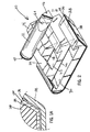
- Figure 2 illustrates a partially assembled perspective view of the embodiment of the present invention shown in Fig. 1 ;
- Figure 3 illustrates a front view of the embodiment of the present invention shown in Figs. 1 and 2 ;
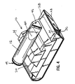
- Figure 4 illustrates a fully assembled perspective view of the embodiment of the present invention shown in Figs. 1-3 ;
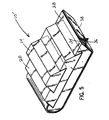
- Figure 5 is a fully assembled perspective view of an alternative embodiment of the invention.
- Figure 6 is a view similar to Fig. 1 showing an alternative means for removably attaching sanding material to the sanding surfaces.
- FIG. 1 A side view of the preferred embodiment of the present invention showing a sanding tool 10 is depicted in Fig. 1 .
- the sanding tool 10 includes a generally cylindrical handle 12 attached to a first sanding member 14.
- the first sanding member 14 has a dovetail shape and includes a first sanding surface 16 covered with a first vinyl backing layer 18.
- a vinyl backing layer 18 runs along a substantially planar bottom of first sanding surface 16 and also extends upwardly for a distance along inwardly angled ends of the first sanding surface 16.
- the sanding tool 10 also includes a second sanding member 20 having a dovetail-shaped channel 22 notched into the second sanding member 20 such that the first sanding member 14 fits into the channel 22 in order to removably couple the second sanding member 20 to the first sanding member 14.
- the channel 22 in the second sanding member 20 is configured such that the first vinyl backing layer 18 is substantially covered by the second sanding member 20 when the second sanding member 20 is coupled to the first sanding member 14.
- the second sanding member 20 includes a second sanding surface 24 covered with a second vinyl backing layer 26.
- the vinyl backing layer 26 runs along a substantially planar bottom of second sanding surface 24 and also runs upwardly for a distance along inwardly angled ends of the second sanding surface 24.
- a third sanding member 28 is configured with a dovetail-shape channel 30 corresponding to the dovetail-shape of the second sanding member 20 such that the channel 30 in the third sanding member 28 is configured to receive the second sanding member 20 and to cover the second vinyl backing layer 26 when the third sanding member 28 is removably coupled to the second sanding member 20.
- the third sanding member 28 includes a third sanding surface 32 covered by a vinyl backing layer 34.
- a layer of pressure sensitive adhesive (PSA) 36 is applied to an upper surface of a sanding material 38.
- the PSA layer 36 frictionally adheres well to the vinyl backing layer 34, but may be easily peeled away for replacement of the sanding material 38.
- the vinyl backing layer 34 and the PSA layer 36 thus permit the removable attachment of the sanding material 38 to the third sanding surface 32.
- the sanding member 28 also includes a curved end portion 40 and an angled end portion 42.
- the vinyl backing layer 34 runs along a substantially planar bottom surface of the third sanding surface 32 and also runs upwardly along the entire length of curved and angled end portions 40 and 42, respectively.
- the handle 12 of the sanding tool 10 may also include first and second auxiliary members 44 and 46 secured on opposite ends for enabling removable and replaceable attachment of sanding materials 48, 50, respectively.
- First auxiliary member 44 includes a circular sanding face 52 having a compressible foam member 54 of similar shape and size attached thereto such as by permanent adhesive.
- a vinyl hacking layer 56 corresponding to the size and shape of the foam member 54 is attached such as by adhesive, to the exterior of the foam member 54.
- a pressure sensitive adhesive (PSA) 58 may be applied to an inner surface of sanding material 48.
- Handle 12 is configured with three tapered surfaces 60 ( Fig.
- second auxiliary member 46 includes a triangularly-shaped face 62 having a compressible foam member 64 of similar shape and size attached thereto, such as by permanent adhesive.
- a vinyl backing layer 66 corresponding to the size and shape of the foam member 64 is attached, such as by adhesive, to the exterior of the foam member 64.
- a pressure sensitive adhesive (PSA) 68 may be applied to the inner surface of sanding material 50. As explained above, the PSA layers 58, 68 will adhere to the respective vinyl backing layers 56, 66 but may be easily peeled away for selective replacement of the respective sanding materials 48, 50.
- the handle 12 of the sanding tool 10 can be constructed from a variety of materials.
- sanding tool 10 is formed from a somewhat compressible material such as natural or synthetic rubber. Rubber materials of varying compressibility (durometer) may be used. It should also be understood that the sanding tool 10 may include more than three sanding members 14, 20, 28 of the preferred embodiment.
- the sanding tool 10 in Fig. 1 is shown such that the second sanding member 20 and the third sanding member 28 are not coupled to the first sanding member 14 and the handle 12 in operation.
- Such a configuration would allow a user of the sanding tool 10 desiring to perform finishing and sanding work to grip the handle 12 and utilize only the first sanding member 14 which can be covered by a sanding material 70 having a pressure sensitive adhesive (PSA) 72 that will removably adhere to the vinyl backing layer 18.
- PSA pressure sensitive adhesive
- the user of the sanding tool 10 would also be able to utilize the auxiliary sanding members 44 and 46 and auxiliary sanding members 48 and 50 if the sanding tool were so equipped.
- the user of the sanding tool 10 could couple the second sanding member 20 to the first sanding member 14 by sliding the first sanding member 14 into the channel 22 of the second sanding member 20.
- the user of the sanding tool 10 would then be able to utilize the second sanding surface 24 after covering the vinyl backing layer 26 with a sanding material 74 having a pressure sensitive adhesive (PSA) 76 that will removably adhere to the vinyl backing layer 26.
- PSA pressure sensitive adhesive
- the sanding material 70 would need to be peelably removed from the vinyl backing layer 18 of the first sanding member 14 prior to inserting the first sanding member 14 into the channel 22 of the second sanding member 20.
- a user of the sanding tool 10 may also removably couple the third sanding member 28 to the second sanding member 20, the third sanding member 28 having the third sanding surface 32 covered by the third sanding material 38.
- the third sanding member 28 is the last sanding member available to couple the sanding tool 10. This is evident as the third sanding member 28 includes the curved end portion 40 and the angled end portion 42. It should he noted that the angled end portion 42 and the curved end portion 40 are part of the third sanding surface 32 and can be configured in different shapes and angles to accommodate the user.
- Fig. 2 depicts a perspective view of the sanding tool 10 of the present invention. This view is intended to show how the sanding members 14, 20, 28 are configured to removably couple to and uncouple from each other. It should be understood that the sanding tool 10 as depicted in Fig. 2 is not necessarily ideally configured for sanding and/or finishing. Rather this figure is intended to show how the sanding members 14, 20, 28 are coupled together. Still referring to Fig. 2 , the first and second auxiliary sanding members 44 and 46 and the respective auxiliary sanding faces 52 and 62 arc constructed in respective circular and triangular shapes. While these shapes are advantageous for sanding and/or finishing in corners, it is contemplated that alternative embodiments can include any other shapes the user may find helpful for sanding and/or finishing.
- Figure 3 depicts a front view of the sanding tool 10 of the present invention.
- the sanding members 14, 20, 28 arc coupled together such that a user of the tool 10 would grip the handle 12 and utilize the third sanding member 28 and the third sanding material 38.
- the user of the sanding tool 10 could also utilize the curved and angled end portions 40 and 42 covered by sanding material 38 to sand and/or finish.
- Figure 4 depicts a perspective view of the fully assembled sanding tool 10. This figure is intended to illustrate how the first vinyl covered sanding surface 16 of first sanding member 14 fits into channel 22 of the second sanding member 20, and how the second vinyl cover sanding surface 24 of the second sanding member 20 fits into the channel 30 of the third sanding member 28 which is equipped with sanding material 38. It should be understood that any of the sanding surfaces described above in the present invention have a sanding material fixed to the sanding surface before sanding and/or finishing can be performed with individual members 14, 20, 28.
- Figure 5 is a view similar to Fig. 4 which illustrates a sanding tool 10 having the cylindrical handle 12 deleted.
- a user will simply grasp the opposite sides of the first sanding member 14 which define a handle.
- the first sanding member 14 in Fig. 5 can be removed so that the interlocked second and third sanding members 20, 28 respectively, can be used for sanding.
- the sides of the second sanding member 20 define the handle.
- Figure 6 illustrates an alternative embodiment of the invention which shows an alternative means of removably attaching the sanding materials 70, 74, 38 to the respective sanding members 14, 20, 28.
- any of the respective sanding surfaces 16,24,32 can be adhesively covered with one type of a hook and loop fastener 78 (e.g. Velcro).
- a cooperating hook and loop fastener 80 is attached such as by adhesive to the back face of sanding materials 70, 74, 38 respectively.
- the foam materials 54, 64 on the opposite ends of the handle 12 can be adhesively covered with hook and loop fastener 78 to cooperate with book and loop fasteners 80 secured on the sanding materials 48 and 50 so that the sanding materials 48 and 50 may be easily removed or replaced if desired.
- the present invention thus discloses two separate embodiments for temporarily affixing sanding materials to various sanding surfaces.
Landscapes
- Engineering & Computer Science (AREA)
- Mechanical Engineering (AREA)
- Finish Polishing, Edge Sharpening, And Grinding By Specific Grinding Devices (AREA)
- Supports Or Holders For Household Use (AREA)
- Polishing Bodies And Polishing Tools (AREA)
Applications Claiming Priority (1)
| Application Number | Priority Date | Filing Date | Title |
|---|---|---|---|
| US12/273,012 US8210910B2 (en) | 2008-11-18 | 2008-11-18 | Multi-faceted sanding/finishing tool |
Publications (2)
| Publication Number | Publication Date |
|---|---|
| EP2361724A2 true EP2361724A2 (fr) | 2011-08-31 |
| EP2361724A3 EP2361724A3 (fr) | 2011-12-21 |
Family
ID=42172395
Family Applications (1)
| Application Number | Title | Priority Date | Filing Date |
|---|---|---|---|
| EP09014552A Withdrawn EP2361724A3 (fr) | 2008-11-18 | 2009-11-23 | Outil de ponçage/finition à plusieurs facettes |
Country Status (3)
| Country | Link |
|---|---|
| US (1) | US8210910B2 (fr) |
| EP (1) | EP2361724A3 (fr) |
| MX (1) | MX2009012448A (fr) |
Families Citing this family (10)
| Publication number | Priority date | Publication date | Assignee | Title |
|---|---|---|---|---|
| US20130045668A1 (en) * | 2011-05-25 | 2013-02-21 | Saint-Gobain Abrasifs | Multi-sided shaped abrasive sanding aid |
| FI20115647A0 (fi) * | 2011-06-23 | 2011-06-23 | Mika Ahonen | Järjestely lattian hiontaan |
| US8834235B1 (en) * | 2013-09-27 | 2014-09-16 | Thomas E. Foster | Flexible sander |
| US9156135B1 (en) | 2014-09-15 | 2015-10-13 | Thomas E. Foster | Flexible sander |
| ITVR20150011U1 (it) * | 2015-03-24 | 2016-09-24 | Aros Srl | Utensile per la lucidatura e/o lappatura di superfici di materiali lapidei. |
| US20160361797A1 (en) * | 2015-06-12 | 2016-12-15 | Speare Tools, Inc. | Sanding sponge with an adhesive and/or method for assembling the same |
| DE102016114096A1 (de) * | 2016-07-29 | 2018-02-01 | Tts Microcell Gmbh | Oberflächen-Bearbeitungsgerät mit einer Krümmungspartie |
| US10603758B1 (en) * | 2016-12-08 | 2020-03-31 | Moog Inc. | Method, apparatus and computer-readable medium for deburring |
| USD875501S1 (en) * | 2018-04-23 | 2020-02-18 | Ted Randall Dedrick | Sanding tool |
| USD1035411S1 (en) * | 2024-03-22 | 2024-07-16 | Wenfeng Li | Knife sharpener |
Family Cites Families (37)
| Publication number | Priority date | Publication date | Assignee | Title |
|---|---|---|---|---|
| US137763A (en) * | 1873-04-15 | Improvement in scythe-rifles | ||
| US129103A (en) * | 1872-07-16 | Improvement in rifles for sharpening harvester-cutters | ||
| US1332101A (en) * | 1920-02-24 | Razor hone and strop | ||
| US148698A (en) * | 1874-03-17 | Improvement in slate and blackboard rubbers | ||
| US785264A (en) * | 1904-06-20 | 1905-03-21 | George E Maier | Razor-strop. |
| US1067280A (en) * | 1912-01-19 | 1913-07-15 | Abraham Smilovetz | Scouring and finishing tool. |
| DE389344C (de) | 1923-03-04 | 1924-02-05 | Wilhelm Simon | Handschleif- oder Polierkoerper |
| US1520642A (en) * | 1923-10-05 | 1924-12-23 | Giroux Gilbert August | Sandpaper holder |
| US1931718A (en) * | 1929-09-16 | 1933-10-24 | Carborundum Co | Fluted rub brick |
| US2904939A (en) * | 1958-11-06 | 1959-09-22 | Raia Peter | Portable adjustable sanding device |
| US3034267A (en) * | 1959-11-04 | 1962-05-15 | Bartholomew E Feeney | Manual contour sander |
| US4189874A (en) * | 1977-06-20 | 1980-02-26 | Labriola Daniel J | Hand held pocket size ski repair and maintenance tool |
| US4249349A (en) | 1978-11-06 | 1981-02-10 | Minnesota Mining And Manufacturing Company | Elongate sanding block |
| US4317248A (en) | 1978-12-18 | 1982-03-02 | T. S. Simms & Co. Limited | Hand tools |
| US4263755A (en) * | 1979-10-12 | 1981-04-28 | Jack Globus | Abrasive product |
| US4845901A (en) | 1987-09-14 | 1989-07-11 | Bass Cabinet Manufacturing, Inc. | Tool kit for finishing slide fitted article of furniture |
| FR2635672B1 (fr) | 1988-08-31 | 1991-09-13 | Minnesota Mining & Mfg | Bloc composite polyfonctionnel pour le traitement manuel de surfaces |
| US4918871A (en) * | 1989-05-04 | 1990-04-24 | Widmann James C | Renewable aromatic cedar block |
| US5157879A (en) * | 1990-05-16 | 1992-10-27 | Fletcher Engineering, Inc. | Broadhead arrow sharpener |
| US5040256A (en) * | 1990-07-05 | 1991-08-20 | Mills Norman T | Combination tape measurer and sharpener |
| US5033552A (en) * | 1990-07-24 | 1991-07-23 | Hu Cheng Te | Multi-function electric tool |
| US5170595A (en) * | 1990-12-19 | 1992-12-15 | Wiand Ronald C | Pull tab for velcro backed marble grinding pad and method for removal |
| US5220752A (en) * | 1991-07-22 | 1993-06-22 | Christopher Cheney | Conformable sanding device incorporating a flexible attachment means |
| EP0619165A1 (fr) * | 1993-04-07 | 1994-10-12 | Minnesota Mining And Manufacturing Company | Article abrasif |
| US5392569A (en) | 1993-09-01 | 1995-02-28 | Stickle; Dean | Edger sanding tool |
| US5558572A (en) | 1994-07-26 | 1996-09-24 | Eze-Lap Diamond Products, Inc. | Package/pedestal for sharpening stone |
| US7311591B2 (en) * | 1994-10-11 | 2007-12-25 | 3M Innovative Properties Company | Abrasive materials |
| US6296558B1 (en) | 1999-05-13 | 2001-10-02 | Daniel L. Poole | Sanding device |
| US6368202B1 (en) * | 2000-10-18 | 2002-04-09 | Richard A. Kaiser | Rotary finishing tool and method of making the same |
| JP2002321158A (ja) | 2001-02-20 | 2002-11-05 | Sakura Color Prod Corp | 研磨用具 |
| USD539111S1 (en) * | 2005-03-30 | 2007-03-27 | Tobias Michael Cardew | Manual sharpener |
| US7186174B1 (en) * | 2005-05-09 | 2007-03-06 | Alfred W Arnold | Sanding block holder |
| WO2007103487A1 (fr) | 2006-03-09 | 2007-09-13 | Full Circle International, Inc. | Outil pour travailler une surface |
| US8157622B2 (en) * | 2006-05-19 | 2012-04-17 | Ali Industries, Inc | Composite support structure for use in sanding and sanders formed therefrom |
| US7320634B1 (en) * | 2006-12-01 | 2008-01-22 | 3M Innovative Properties Company | Sanding tool and dust collection system therefor |
| US20080207099A1 (en) * | 2007-02-28 | 2008-08-28 | Brown John E | Resilient abrasive article and method of manufacture |
| US7927192B2 (en) * | 2007-10-17 | 2011-04-19 | Full Circle International, Inc | Tool for working on a surface |
-
2008
- 2008-11-18 US US12/273,012 patent/US8210910B2/en not_active Expired - Fee Related
-
2009
- 2009-11-18 MX MX2009012448A patent/MX2009012448A/es active IP Right Grant
- 2009-11-23 EP EP09014552A patent/EP2361724A3/fr not_active Withdrawn
Also Published As
| Publication number | Publication date |
|---|---|
| US8210910B2 (en) | 2012-07-03 |
| EP2361724A3 (fr) | 2011-12-21 |
| US20100124873A1 (en) | 2010-05-20 |
| MX2009012448A (es) | 2010-07-02 |
Similar Documents
| Publication | Publication Date | Title |
|---|---|---|
| US8210910B2 (en) | Multi-faceted sanding/finishing tool | |
| US8062101B1 (en) | Sanding glove | |
| CA2435855C (fr) | Eponge de poncage | |
| US7488242B2 (en) | Sanding apparatus with molded elastomeric pad | |
| US6227959B1 (en) | Sanding sponge | |
| US4202139A (en) | Conformable hand sanding pad | |
| CA2730301C (fr) | Assemblages de conversion s'utilisant avec un appareil de modification de surface, et procede associe | |
| WO2005051119A3 (fr) | Sac a dos, poignee amovible et assemblage de roulettes associes | |
| US20070284405A1 (en) | Multifunctional holder for handheld power tool bits | |
| US20220379451A1 (en) | Multi-Purpose Tool and Attachments | |
| US20050095968A1 (en) | Sanding block | |
| US7938717B2 (en) | Conformable sanding pad | |
| US6688958B1 (en) | Hand sander | |
| CA2605989C (fr) | Outil de poncage | |
| US20100009610A1 (en) | Non-motorized hand manipulatable surface modifying tool and method of converting the same | |
| US6835032B1 (en) | Rotary power hand tool having a flexible handle and attachment system | |
| US10124463B2 (en) | Sanding pad | |
| US7775855B2 (en) | Sanding tool with rotatable handle | |
| US7500906B2 (en) | Sanding tool with rotatable handle | |
| US20140000083A1 (en) | Compound holding device for retaining tools | |
| JP7390133B2 (ja) | 手首装着用携帯電話機保持具 | |
| JP2003246164A (ja) | バインダー、紙束取付け具及びノート | |
| NZ569561A (en) | Hand-held sheet material holder |
Legal Events
| Date | Code | Title | Description |
|---|---|---|---|
| PUAI | Public reference made under article 153(3) epc to a published international application that has entered the european phase |
Free format text: ORIGINAL CODE: 0009012 |
|
| AK | Designated contracting states |
Kind code of ref document: A2 Designated state(s): AT BE BG CH CY CZ DE DK EE ES FI FR GB GR HR HU IE IS IT LI LT LU LV MC MK MT NL NO PL PT RO SE SI SK SM TR |
|
| AX | Request for extension of the european patent |
Extension state: AL BA RS |
|
| PUAL | Search report despatched |
Free format text: ORIGINAL CODE: 0009013 |
|
| AK | Designated contracting states |
Kind code of ref document: A3 Designated state(s): AT BE BG CH CY CZ DE DK EE ES FI FR GB GR HR HU IE IS IT LI LT LU LV MC MK MT NL NO PL PT RO SE SI SK SM TR |
|
| AX | Request for extension of the european patent |
Extension state: AL BA RS |
|
| RIC1 | Information provided on ipc code assigned before grant |
Ipc: B24D 15/02 20060101AFI20111115BHEP |
|
| STAA | Information on the status of an ep patent application or granted ep patent |
Free format text: STATUS: THE APPLICATION IS DEEMED TO BE WITHDRAWN |
|
| 18D | Application deemed to be withdrawn |
Effective date: 20120622 |