EP2361758A2 - Procédé d'ajustement des paramètres de pressage d'une presse à poudre céramique ou métallique et presse à poudre céramique ou métallique destinée à l'exécution du procédé - Google Patents
Procédé d'ajustement des paramètres de pressage d'une presse à poudre céramique ou métallique et presse à poudre céramique ou métallique destinée à l'exécution du procédé Download PDFInfo
- Publication number
- EP2361758A2 EP2361758A2 EP11001543A EP11001543A EP2361758A2 EP 2361758 A2 EP2361758 A2 EP 2361758A2 EP 11001543 A EP11001543 A EP 11001543A EP 11001543 A EP11001543 A EP 11001543A EP 2361758 A2 EP2361758 A2 EP 2361758A2
- Authority
- EP
- European Patent Office
- Prior art keywords
- pressing
- press
- measuring
- fixed stop
- sequence
- Prior art date
- Legal status (The legal status is an assumption and is not a legal conclusion. Google has not performed a legal analysis and makes no representation as to the accuracy of the status listed.)
- Granted
Links
Images

Classifications
-
- B—PERFORMING OPERATIONS; TRANSPORTING
- B30—PRESSES
- B30B—PRESSES IN GENERAL
- B30B11/00—Presses specially adapted for forming shaped articles from material in particulate or plastic state, e.g. briquetting presses, tabletting presses
- B30B11/005—Control arrangements
-
- B—PERFORMING OPERATIONS; TRANSPORTING
- B22—CASTING; POWDER METALLURGY
- B22F—WORKING METALLIC POWDER; MANUFACTURE OF ARTICLES FROM METALLIC POWDER; MAKING METALLIC POWDER; APPARATUS OR DEVICES SPECIALLY ADAPTED FOR METALLIC POWDER
- B22F3/00—Manufacture of workpieces or articles from metallic powder characterised by the manner of compacting or sintering; Apparatus specially adapted therefor ; Presses and furnaces
- B22F3/02—Compacting only
- B22F3/03—Press-moulding apparatus therefor
-
- B—PERFORMING OPERATIONS; TRANSPORTING
- B28—WORKING CEMENT, CLAY, OR STONE
- B28B—SHAPING CLAY OR OTHER CERAMIC COMPOSITIONS; SHAPING SLAG; SHAPING MIXTURES CONTAINING CEMENTITIOUS MATERIAL, e.g. PLASTER
- B28B17/00—Details of, or accessories for, apparatus for shaping the material; Auxiliary measures taken in connection with such shaping
- B28B17/0063—Control arrangements
- B28B17/0081—Process control
-
- B—PERFORMING OPERATIONS; TRANSPORTING
- B28—WORKING CEMENT, CLAY, OR STONE
- B28B—SHAPING CLAY OR OTHER CERAMIC COMPOSITIONS; SHAPING SLAG; SHAPING MIXTURES CONTAINING CEMENTITIOUS MATERIAL, e.g. PLASTER
- B28B3/00—Producing shaped articles from the material by using presses; Presses specially adapted therefor
- B28B3/02—Producing shaped articles from the material by using presses; Presses specially adapted therefor wherein a ram exerts pressure on the material in a moulding space; Ram heads of special form
- B28B3/08—Producing shaped articles from the material by using presses; Presses specially adapted therefor wherein a ram exerts pressure on the material in a moulding space; Ram heads of special form with two or more rams per mould
- B28B3/086—The rams working in different directions
-
- B—PERFORMING OPERATIONS; TRANSPORTING
- B22—CASTING; POWDER METALLURGY
- B22F—WORKING METALLIC POWDER; MANUFACTURE OF ARTICLES FROM METALLIC POWDER; MAKING METALLIC POWDER; APPARATUS OR DEVICES SPECIALLY ADAPTED FOR METALLIC POWDER
- B22F3/00—Manufacture of workpieces or articles from metallic powder characterised by the manner of compacting or sintering; Apparatus specially adapted therefor ; Presses and furnaces
- B22F3/02—Compacting only
- B22F3/03—Press-moulding apparatus therefor
- B22F2003/033—Press-moulding apparatus therefor with multiple punches working in the same direction
Definitions
- the invention relates to a method for adjusting the press parameter of a ceramic or metal powder press with the above-mentioned features according to claim 1 or to a ceramic or metal powder press for carrying out the method with the above-mentioned features according to claim 6.
- Ceramic or metal powder presses have a die in whose die opening a powder or granules is pressed into a compact by means of stamping.
- the punches are each seated on stamp carriers, which are adjustably arranged and controllable along a punch movement path as a function of adjustable pressing parameters.
- a press drive is driven, which applies a main pressing force to press the compact by means of the punch.
- two or more punches are guided into the die opening of one or both sides.
- Each of the stamp sits on a separate stamp carrier.
- the punch carriers are adjustable relative to a base support or a base plate in order to be able to adjust the individual punches relative to one another in different positions.
- the individual punch carriers are supported by so-called fixed stops relative to the base carrier, so that in each case on one side of the Die opening considered the stamp relative to each other and occupy a defined pressing position relative to the stamp carriers and base members.
- a problem in the operation of such presses is that when filling the powder or granules in the die opening fluctuations of the filled powder and powder composition occur, which in a conventional control on pressing forces or individual pressing positions of the individual dies by means of predetermined set values to errors part height of the pressed Lead the pressed body.
- the object of the invention is to provide a method for adjusting the press parameter of a ceramic or metal powder press or a ceramic or metal powder press for carrying out such a method so as to compensate for changing ones Press conditions an improved and more accurate adjustment of press parameters is made possible.
- a method for adjusting the press parameter of a ceramic or metal powder press in which in a die opening of a die by means of pistons carried on stamp carriers stamped powder and / or granules, a compact is pressed to a predetermined Press Economics-, wherein during pressing within a press cycle for pressing a At least one actuator is controlled along a succession of desired values of such a compact, while compliance with the sequence of desired values is checked during the pressing, and a readjustment of the at least one actuator is carried out in the event of a deviation from the sequence of desired values, in particular greater than a tolerance value.
- a distance between a first measuring point on a fixed stop, which supports one of the punch carrier on one side of the die opening, and a second measuring point on a fixed stop, which one of the punch carrier on a side opposite thereto the die opening is supported, is measured.
- a control signal is thus regulated in particular, which serves to drive the actuator.
- measuring points By measuring measuring points, that is to say predeterminable points on such fixed stops supporting the punch carriers, measuring points are determined which lie as close as possible to the punches which dive into the die opening during the pressing. As a result, an influence of compressions and thermal changes which can occur between different pressing cycles is best eliminated, so that the multiplicity of two or more of the measured distances and the setpoint values predetermined for them are not or only to a small extent influenced by such influences.
- deviations of the distance measured during a pressing cycle from the desired value advantageously correspond to a variation of the quantity of the powder and / or granulate to be pressed in the die opening. Accordingly, a deviation measured in this way can be used as a direct control variable in order to be able to correct the at least one actuator, in particular a control signal for the main press drive, during the same press cycle.
- effects influencing the measurements such as bending or compression of the height of an upper piston position measured to date for regulation, do not affect this distance measurement if the distance is determined as closely as possible to the resulting pressed part.
- the tolerance value can be suitably determined depending on the accuracy of the pressed body dimension to be achieved. In extreme cases, an identity of the measured value and the setpoint or a tolerance value equal to zero may be required.
- a position of the end stops of the fixed stops facing the punch carrier to be supported, a position of markings spaced therefrom against the fixed stops and / or a position of measuring elements leading away from the fixed stop are used as the measuring points above or below the die. This makes it possible to measure at positions that give almost measured values, as if directly a stamp position would be measured, which is not possible because of the immersion of the stamp in the die opening. Also, compared to measurements on the stamp carriers influences of their deflection during pressing completely or at least almost completely excluded.
- a position is advantageously used on at least one centrally located fixed stop, in particular a fixed stop which lies in line of force between the die opening of the die and a force introduction region of a / of the press drive.
- a press drive in particular a main press cylinder
- the main press drive Under the press drive is the main press drive to understand, which applies the actual pressing force.
- auxiliary drives such as the actuators, which cause movement of the punch carrier relative to each other, since their influence on the one hand negligible relative to the press drive with regard to the high force differences and their effect in particular to the Pressend ein out when applying the punch carrier to the fixed stops in Essentially neutralized.
- Such auxiliary drives, in particular auxiliary cylinders serve e.g. for adjusting the individual punch carrier relative to each other. However, their adjustment usually does not cause any force acting on the powder pressing force, since they essentially serve to adjust the individual punch carrier when removing a pressed part.
- the main press drive in addition to a main press cylinder, other drive forms can also be used, such as e.g. mechanical drives, pneumatic drives or electric motor drives.
- a ceramic or metal powder press with a die opening of a die and punches carried on stamp carriers, which are arranged and adjustable relative to one another, is preferred, so that from powder and / or granules a pressed body can be pressed to a predetermined pressed body dimension, and with a control device which is designed and / or accesses a program during the Pressing within a press cycle for pressing such a compact at least one actuator along a sequence of setpoints to control, for which during the pressing compliance with the sequence of setpoints can be tested and in a deviation from the sequence of setpoints - in particular greater tolerance value - a readjustment of at least one actuator is feasible.
- the press is advantageous by a position measuring device with which, for comparison with the sequence of nominal values, a distance between a first measuring point on a fixed stop, which supports one of the punch carrier on one side of the die opening, and a second measuring point on a fixed stop, which is one of the punch carrier is supported on an opposite side of the die opening, is measurable.
- the position measuring device is preferably designed as a fixed stop distance measuring device and as such measures measuring points of a position of the punch carrier to be supported facing end side edges of the fixed stops, a position of spaced therefrom marks on the fixed stops and / or a position away from the fixed stop measuring elements.
- the position-measuring device may advantageously be designed as a fixed-stop distance measuring device, wherein at least one of the measuring points is located at a centrally located fixed stop, in particular a fixed stop, which is arranged in line of force between the die opening of the die and a force introduction region of a press drive.
- a position-measuring device which has measuring elements, the one of the fixed stops or one of the base support away and to a Lead measuring device out.
- a direct distance measurement can be carried out without detouring over two position measured values and a calculated distance determination.
- rigid linkages which are easy to assemble and, as mechanical elements, are not rendered useless by the influence of dust or whirled-up powder residues.
- At least one of the fixed stops and a base support supporting them at least in the final press position can be designed as at least two independent components, wherein the measuring point lies on the fixed stop itself. This solution is particularly preferred because the closer the measuring point is to the die opening, the more advantageous the effect of readjustment.
- At least one of the fixed stops has a base carrier or is rigidly connected at least in the final press position in the force flow line with the base carrier, wherein the measuring point is located on the base carrier.
- the control device of the press is in particular designed and / or accesses a program for carrying out such a preferred method.
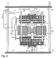
- Fig. 1 and 2 can be seen centrally in an exemplary ceramic or metal powder press a die 0 is arranged in the die opening so-called powder P is compressible into a compact T.
- powder P is generally understood a powdered and / or granular material.
- punches 7, 8, 17, 18 can be inserted into the die opening or relative to the die 0.
- the punches 7, 8, 17, 18 are each supported by a punch carrier 3, 4, 1, 2 or are fastened to the stamp carriers 3, 4, 1, 2. An adjustment of the stamp 7, 8, 17, 18 is carried out accordingly by an adjustment of the punch carrier 3, 4, 1, 2 along the punch movement path.
- two of the punches 7, 8 can be inserted from below or two punches 17, 18 from above into the die opening. However, more or less punch and corresponding punch carrier can be used in such a press arrangement.
- the individual die carriers 3, 4, 1 , 2 by means of actuators 9 - 12 relative to an associated upper base support. 5 or a lower base support 6 adjustably mounted.
- the actuators 9 - 12 are formed by hydraulic adjusting drives. However, other drive systems can be used.
- guide rods 13 are attached to the lower base support 13 parallel to the punch path, along which the individual punch carrier 1 - 4 and the upper base support 5 and the die 0 are mounted adjustable.
- This arrangement can be fixed directly on a lower press frame 14 of the actual press by means of the lower base support 6, which is also referred to as a base plate.
- the exemplary press has from the lower press frame 14 upwardly leading side press frame 15, which on the upper side of the above-described arrangement in a transversely over the arrangement leading upper press frame 16 lead.
- an actual press drive is attached as an actuator 29, which applies a main pressing force.
- the press drive can be driven mechanically, electrically or hydraulically and brings about a pressing force on the upper base support 5 for pressing, so that the arrangement of the base supports 5, 6, the stamp carriers 1 - 4 arranged therebetween and the punches 7, 8, 17 fastened thereon , 18 is compressed along the stamp path.
- the base supports 5, 6 or the base plates are not firmly inserted into the press frame 14-16, but are releasably inserted again via adapter fastening elements 28.
- a fixed to a substrate attachment of the lower base support 6 to the lower press frame 14 can between the lower base support 6 and the lower press frame 14 optionally also an alternative or further press drive 29 * be arranged.
- fixed stops 19, 20 are respectively arranged between the upper base carrier 5 and the upper punch carriers 1, 2, which in the final press position constitute a rigid abutment of the punch carriers 1 , 2 effect on the upper base support 5.
- the fixed stop 19, which is designed as a fixed stop for the stamp carrier 2 furthest from the upper base support 5, protrudes there, just like a piston rod of the actuator 10 for this punch carrier 2, through a passage opening 21 which is formed in the stamp carrier 1 lying above it. therethrough.
- the lower punch carrier 3, 4 are supported relative to the lower base support 6 via fixed stops 22, 23.
- a fixed stop 19, 20, 22, 23 is thus understood in particular a stop, which is arranged as a support element for a punch carrier in the force path between the filled with powder P die opening and a press drive or a press base and on which is supported in a final press position of the punch carrier ,
- the fixed stop thus the possible movement distance of the adjacent stamp carrier and attached stamp is limited.
- the Pressend ein is understood in particular that any further increasing pressing forces cause any changes in the position or the distance between the moving stamp carriers and the fixed stop more.
- control device C For controlling the various actuators 9 - 12 and the press drive as the actuator 29 is a control device C, which corresponding control signals s1, s2, s3, ..., s29 applies to this.
- the control device C can apply further control signals, for example, to motor-adjustable fixed stops, which can be adapted as further pressing parameters for adapting the pressed-body dimension.
- the arrangement additionally has at least one position measuring device S which is used to determine a current position of at least part of the fixed stops 19, 20, 22, 23 and optionally a current position of the upper or Lower base support 5, 6 is arranged in the press.
- the control device C is a distance or a distance d (t) of two measuring points or points on the fixed stops 19, 20, 22, 23, in particular a fixed stop 19 above or a fixed stop 23 below the die opening or die (0) at various times t1, t2, t3, ... of the advancing time t during pressing.
- the two measuring points on the fixed stops 19, 23 are preferably set as close as possible to the die opening, in particular with regard to a force flow in the final press position. This results in a distance d (t), which is more independent of a commonly measured Distance between the upper press frame 16 and the upper base support 5 results. This applies even with different powder fillings of the die opening between different pressing cycles.
- an image can optionally be taken by means of a camera in which the control device C and a suitable program are used to search for desired structures, for example a fixed stop edge or a mark on the fixed stop.
- a first method sequence currently measured positions or distances d (t1), d (t2), d (t3) or corresponding measured values m2, m4 are measured at different times t1, t2, t3 and in particular after a pressing of such a compact T with the desired predetermined compact dimension as reference values, reference distance or nominal values d soll (t) are stored in the memory device M and / or the processor C.
- desired values d soll (t) can also be determined in other ways, in particular on the basis of the powder quality and the predetermined compact dimension by calculation.
- the individual measured positions or distances d (t) are measured independently of fixed reference positions h0, eg a height of the lower press frame 14 or a height h0 * of the upper press frame 16.
- a preferred method for press parameter adjustment comprises a plurality of individual method steps S1-S5.
- reference values or preferably setpoint values d (t) determined therefrom are stored in the memory device M.
- a first method step S1 it is checked whether the desired compact dimension dT end has been reached. If so, the pressing process or at least the readjustment of the at least one actuator 29 is terminated. If not, in a second method step S2 a measurement of the instantaneous positions of the fixed stops 19, 23 is carried out and the resulting measured values m2, m4 or the distance d (t) between them are determined.
- a subsequent third method step S3 relates to a check of the distance d (t) just measured in relation to the setpoint value d soll (t) stored for the corresponding time t1, t2,....
- the method jumps to the first method step S1 while maintaining the control.
- step S5 the pressing means are changed by the control device C such that a readjustment of the at least an actuator 29 still in the same press cycle is made so that the compact to be pressed in this cycle T is pressed with the desired compact dimension.
- a pressing force or a pressing pressure p which acts on the entire arrangement of the press components via the press drive 29, is readjusted. Thereafter, the first step S1 is jumped.
- the measured values m2, m3 it is particularly preferable to measure the respective instantaneous position of the front side edges of the fixed stops 19, 22 facing the punch carrier 2, 3 to be supported, and then determine their spacing therefrom.
- markings x which are spaced therefrom may also be formed on the fixed stops 20, 23, which are detected for distance measurement, so that any occlusions of the end faces in the case of easily deflecting punch carriers do not falsify the measurement result.
- Fig. 1 shows the components of the ceramic or metal powder press during a pressing operation before reaching the final press position for example, a third time t3 in the distance-time diagram, which exemplifies a curve from setpoint values d soll (t) and a curve at the momentary pressing process measured distances d (t) shows.
- the punches 7, 8, 17, 18 already compress the powder P present in the die opening.
- the stamp carriers 1 - 4 are not yet on their fixed stops 20, 19, 22 and 23 respectively. Nevertheless, powder fluctuations already have an influence on this pressing stage, which is why the checking of the distance d (t) and, if necessary, the readjustment of the control value 29 is already carried out. It is particularly advantageous to start measuring and comparing the distances shortly before reaching the final press position.
- Fig. 2 In contrast, shows the Pressend ein in which the powder was pressed in the die opening to the compact T.
- the punch carrier 1 - 4 firmly supported on the fixed stops 20, 19, 22 and 23 respectively.
- FIG. 2 a preferred embodiment of a position measuring device S *.
- This position measuring device S * or parts thereof are arranged directly on components of the pressing tool, for example on one of the fixed stops 23 or one of the base supports 5, 6.
- the position measuring device S * extends starting parallel to the pressing direction leading laterally next to the stamp carriers 3, 4, 1 , 2 and optionally base supports 6, 5.
- a measuring element S ° laterally leads away from one of the lower fixed stops 23, wherein the measuring element S ° moves in the case of movement of the fixed stop 23 along the adjustment direction of the punch uniformly together with the movement of the fixed stop 23.
- Another such measuring element S ° leads laterally away from the upper base body 5.
- the further measuring element S ° moves longitudinally in the case of a movement of the base body 5
- the adjusting direction of the punches is uniform along with the movement of the base body 5.
- elements, in particular rod-shaped elements of the two measuring elements S ° project substantially into one another in a measuring device. The measuring device can thus determine a relative adjustment of the two measuring elements S ° and thus directly a change in the distance d (t).
- height-adjustable fixed stops are also possible as these, if at all, are only adjusted between press cycles and act as rigid components during a press cycle.
- Described above is to determine the set values and the distances during a pressing operation at predetermined times during the pressing. However, this does not rule out using a different reference as a criterion for the measurements, for example taking the distance measurements when certain pressing forces or pressures are reached.
Landscapes
- Engineering & Computer Science (AREA)
- Mechanical Engineering (AREA)
- Chemical & Material Sciences (AREA)
- Ceramic Engineering (AREA)
- Manufacturing & Machinery (AREA)
- Automation & Control Theory (AREA)
- Press-Shaping Or Shaping Using Conveyers (AREA)
- Powder Metallurgy (AREA)
- Presses And Accessory Devices Thereof (AREA)
Applications Claiming Priority (1)
| Application Number | Priority Date | Filing Date | Title |
|---|---|---|---|
| DE201010008986 DE102010008986A1 (de) | 2010-02-24 | 2010-02-24 | Verfahren zur Pressparameteranpassung einer Keramik- oder Metallpulverpresse und Keramik- oder Metallpulverpresse zum Durchführen des Verfahrens |
Publications (3)
| Publication Number | Publication Date |
|---|---|
| EP2361758A2 true EP2361758A2 (fr) | 2011-08-31 |
| EP2361758A3 EP2361758A3 (fr) | 2014-01-15 |
| EP2361758B1 EP2361758B1 (fr) | 2016-04-20 |
Family
ID=43797836
Family Applications (1)
| Application Number | Title | Priority Date | Filing Date |
|---|---|---|---|
| EP11001543.5A Active EP2361758B1 (fr) | 2010-02-24 | 2011-02-24 | Procédé d'adjustement des paramètres de pressage d'une presse à poudre céramique ou métallique et presse à poudre céramique ou métallique destinée à l'exécution du procédé |
Country Status (2)
| Country | Link |
|---|---|
| EP (1) | EP2361758B1 (fr) |
| DE (1) | DE102010008986A1 (fr) |
Cited By (5)
| Publication number | Priority date | Publication date | Assignee | Title |
|---|---|---|---|---|
| DE102012019312A1 (de) * | 2012-10-01 | 2014-04-03 | Dorst Technologies Gmbh & Co. Kg | Verfahren zum Steuern einer Keramik- und/oder Metallpulver-Presse bzw. Keramik- und/oder Metallpulver-Presse |
| ITMO20130028A1 (it) * | 2013-02-08 | 2014-08-09 | Mec Ferretti Claudio S R L Off | Stampo perfezionato per piastrelle ceramiche. |
| DE102013113665A1 (de) * | 2013-12-06 | 2015-06-11 | Fette Compacting Gmbh | Presse |
| EP3170654A1 (fr) * | 2015-10-16 | 2017-05-24 | Dorst Technologies GmbH & Co. KG | Outil de presse en céramique et/ou en poudre métallique, presse et procédé de montage d'un dispositif de compression de poudre métallique et/ou de céramique |
| EP4079427A1 (fr) * | 2021-04-22 | 2022-10-26 | GKN Sinter Metals Engineering GmbH | Procédé de détermination d'un paramétré d'une matière et outil de compression destiné à la fabrication d'un comprimé cru |
Families Citing this family (3)
| Publication number | Priority date | Publication date | Assignee | Title |
|---|---|---|---|---|
| CN104384513B (zh) * | 2014-12-09 | 2016-05-11 | 常熟市华德粉末冶金有限公司 | 粉末冶金侧孔成形模具 |
| DE102017004803A1 (de) | 2017-05-18 | 2018-11-22 | Cosateq Gmbh | Verfahren zum Betrieb einer Pulverpresse mit Lagenregelung und Pulverpresse zur Ausführung des Verfahrens |
| DE102017114458B4 (de) * | 2017-06-29 | 2019-10-10 | Gkn Sinter Metals Engineering Gmbh | Ebenenplatte eines Pressenwerkzeugs |
Family Cites Families (10)
| Publication number | Priority date | Publication date | Assignee | Title |
|---|---|---|---|---|
| JPH0791568B2 (ja) * | 1987-04-14 | 1995-10-04 | 株式会社ヨシツカ精機 | 粉末成形用サイジングプレス |
| DE3919821C2 (de) * | 1989-06-15 | 1994-04-07 | Mannesmann Ag | Verfahren und Vorrichtung zum Herstellen von maßhaltigen Preßlingen |
| JPH0557497A (ja) * | 1991-09-04 | 1993-03-09 | Sumitomo Electric Ind Ltd | Nc粉末成形機 |
| JPH07115234B2 (ja) * | 1991-11-25 | 1995-12-13 | 株式会社ヨシツカ精機 | 粉末成形プレスにおける加圧位置の補正方法 |
| DE9203546U1 (de) * | 1992-03-17 | 1993-07-22 | Komage - Gellner & Co. Maschinenfabrik KG, 54427 Kell | Vorrichtung zum Pressen von Formteilen aus einer feinkörnigen Masse |
| DE10051236A1 (de) * | 2000-10-16 | 2002-04-25 | Dorst Masch & Anlagen | Verfahren und Vorrichtung zum Bestimmen von Pressparametern zum Pressen komplex aufgebauter Presslinge |
| DE10301224A1 (de) * | 2003-01-15 | 2004-08-05 | Maschinenfabrik Lauffer Gmbh & Co Kg | Verfahren zur Endpositionsregelung einer Presse für maßgenaue Formkörper |
| JP2006187793A (ja) * | 2005-01-07 | 2006-07-20 | Hitachi Powdered Metals Co Ltd | 粉末成形装置 |
| EP1849590B1 (fr) * | 2006-04-29 | 2013-05-15 | Fette GmbH | Presse |
| WO2008114827A1 (fr) * | 2007-03-20 | 2008-09-25 | Tungaloy Corporation | Procédé de moulage par compression de plaquette jetable |
-
2010
- 2010-02-24 DE DE201010008986 patent/DE102010008986A1/de not_active Withdrawn
-
2011
- 2011-02-24 EP EP11001543.5A patent/EP2361758B1/fr active Active
Non-Patent Citations (1)
| Title |
|---|
| None |
Cited By (13)
| Publication number | Priority date | Publication date | Assignee | Title |
|---|---|---|---|---|
| CN105102208B (zh) * | 2012-10-01 | 2018-01-23 | 道尔斯特技术有限两合公司 | 用于控制陶瓷或金属粉末挤压机的方法及该挤压机 |
| WO2014053120A1 (fr) * | 2012-10-01 | 2014-04-10 | Dorst Technologies Gmbh & Co. Kg | Procédé de commande d'une presse à poudre céramique ou métallique, et presse à poudre céramique ou métallique |
| JP2015530260A (ja) * | 2012-10-01 | 2015-10-15 | ドアスト テクノロジーズ ゲゼルシャフト ミット ベシュレンクテル ハフツング ウント コンパニー コマンディートゲゼルシャフトDorst Technologies GmbH & Co. KG | セラミック粉末または金属粉末プレス機を制御する方法もしくはセラミック粉末または金属粉末プレス機 |
| CN105102208A (zh) * | 2012-10-01 | 2015-11-25 | 道尔斯特技术有限两合公司 | 用于控制陶瓷或金属粉末挤压机的方法以及陶瓷或金属粉末挤压机 |
| DE102012019312A1 (de) * | 2012-10-01 | 2014-04-03 | Dorst Technologies Gmbh & Co. Kg | Verfahren zum Steuern einer Keramik- und/oder Metallpulver-Presse bzw. Keramik- und/oder Metallpulver-Presse |
| US10906262B2 (en) | 2012-10-01 | 2021-02-02 | Dorst Technologies Gmbh & Co. Kg | Method for controlling a ceramic or metal powder press, and ceramic or metal powder press |
| ITMO20130028A1 (it) * | 2013-02-08 | 2014-08-09 | Mec Ferretti Claudio S R L Off | Stampo perfezionato per piastrelle ceramiche. |
| DE102013113665A1 (de) * | 2013-12-06 | 2015-06-11 | Fette Compacting Gmbh | Presse |
| DE102013113665B4 (de) * | 2013-12-06 | 2015-09-03 | Fette Compacting Gmbh | Presse |
| US9314946B2 (en) | 2013-12-06 | 2016-04-19 | Fette Compacting Gmbh | Press |
| EP3170654A1 (fr) * | 2015-10-16 | 2017-05-24 | Dorst Technologies GmbH & Co. KG | Outil de presse en céramique et/ou en poudre métallique, presse et procédé de montage d'un dispositif de compression de poudre métallique et/ou de céramique |
| EP4079427A1 (fr) * | 2021-04-22 | 2022-10-26 | GKN Sinter Metals Engineering GmbH | Procédé de détermination d'un paramétré d'une matière et outil de compression destiné à la fabrication d'un comprimé cru |
| US12358048B2 (en) | 2021-04-22 | 2025-07-15 | Gkn Sinter Metals Engineering Gmbh | Method for determining a parameter of a material and pressing tool for the production of a green compact |
Also Published As
| Publication number | Publication date |
|---|---|
| EP2361758B1 (fr) | 2016-04-20 |
| DE102010008986A1 (de) | 2011-08-25 |
| EP2361758A3 (fr) | 2014-01-15 |
Similar Documents
| Publication | Publication Date | Title |
|---|---|---|
| EP2361758B1 (fr) | Procédé d'adjustement des paramètres de pressage d'une presse à poudre céramique ou métallique et presse à poudre céramique ou métallique destinée à l'exécution du procédé | |
| EP2707208B1 (fr) | Dispositif et procédé d'étalonnage et d'ajustement d'un dispositif de mesure d'une presse à comprimés | |
| EP1844924B1 (fr) | Procédé de régulation de la quantité d'agents actifs de tablettes pendant la production d'une presse rotative pour comprimés | |
| EP2537067B1 (fr) | Procédé et dispositif pour compenser activement une erreur de coin entre des objets pouvant être disposés de manière sensiblement parallèle | |
| EP0403038B1 (fr) | Procédé et dispositif pour fabriquer des articles pressés à dimensions exactes | |
| DE602004010293T2 (de) | Verfahren zur erhöhung der steuergenauigkeit des weges eines produkts in einer richtmaschine mit ineinandergreifenden walzen und zur durchführung desselben verwendete richtanlage | |
| EP3310508B1 (fr) | Procédé et dispositif de fabrication de moules de matière de moulage pour la coulée de métaux | |
| EP2903811A1 (fr) | Procédé de commande d'une presse à poudre céramique ou métallique, et presse à poudre céramique ou métallique | |
| EP2408590B1 (fr) | Procédé et dispositif pour installer une machine | |
| DE69011924T2 (de) | Vorrichtung zur selbsttätigen Korrektur der Pressdichte bei der Herstellung von Dachziegeln. | |
| EP1793946A1 (fr) | Procede pour realiser une piece par cintrage | |
| DE102015221615A1 (de) | System zum Kalibrieren einer Ultraschallschweissvorrichtung | |
| DE102018125919A1 (de) | Verfahren zum Bewegen einer bewegbaren Formaufspannplatte | |
| DE102014213888A1 (de) | Justiervorrichtung und Justierverfahren | |
| DE102010060308B4 (de) | Vorrichtung und Verfahren zur Mehrfachabfüllung hochviskoser Materialien | |
| EP3529065A1 (fr) | Dispositif de compression | |
| EP3953164A1 (fr) | Procédé et dispositif de mesure servant à mesurer ou à étalonner des ustensiles de presses | |
| EP2329895B1 (fr) | Presse à cintrer et outil de cintrage doté d'un dispositif de retenue pour une pièce usinée | |
| EP1849590A1 (fr) | Presse | |
| DE69030307T2 (de) | Verfahren zum Positionieren eines Bauteils, das mit einer Platte verbunden ist oder einen Teil derselben bildet, sowie Vorrichtung zum Durchführen des Verfahren, und nach diesem Verfahren hergestellte Platte | |
| DE102014107127B4 (de) | Pulverpresse | |
| DE10301224A1 (de) | Verfahren zur Endpositionsregelung einer Presse für maßgenaue Formkörper | |
| EP2851187B1 (fr) | Procédé destiné à la fabrication d'une pièce pressée en matériau pulvérulent | |
| EP1053863B1 (fr) | Dispositif pour la fabrication des pièces moulées | |
| CH695668A5 (de) | Mess- und Steuervorrichtung in einer Abkantfpresse. |
Legal Events
| Date | Code | Title | Description |
|---|---|---|---|
| PUAI | Public reference made under article 153(3) epc to a published international application that has entered the european phase |
Free format text: ORIGINAL CODE: 0009012 |
|
| AK | Designated contracting states |
Kind code of ref document: A2 Designated state(s): AL AT BE BG CH CY CZ DE DK EE ES FI FR GB GR HR HU IE IS IT LI LT LU LV MC MK MT NL NO PL PT RO RS SE SI SK SM TR |
|
| AX | Request for extension of the european patent |
Extension state: BA ME |
|
| PUAL | Search report despatched |
Free format text: ORIGINAL CODE: 0009013 |
|
| AK | Designated contracting states |
Kind code of ref document: A3 Designated state(s): AL AT BE BG CH CY CZ DE DK EE ES FI FR GB GR HR HU IE IS IT LI LT LU LV MC MK MT NL NO PL PT RO RS SE SI SK SM TR |
|
| AX | Request for extension of the european patent |
Extension state: BA ME |
|
| RIC1 | Information provided on ipc code assigned before grant |
Ipc: B30B 11/00 20060101AFI20131211BHEP Ipc: B22F 3/03 20060101ALI20131211BHEP Ipc: B28B 3/08 20060101ALI20131211BHEP Ipc: B28B 17/00 20060101ALI20131211BHEP |
|
| 17P | Request for examination filed |
Effective date: 20140709 |
|
| RBV | Designated contracting states (corrected) |
Designated state(s): AL AT BE BG CH CY CZ DE DK EE ES FI FR GB GR HR HU IE IS IT LI LT LU LV MC MK MT NL NO PL PT RO RS SE SI SK SM TR |
|
| GRAP | Despatch of communication of intention to grant a patent |
Free format text: ORIGINAL CODE: EPIDOSNIGR1 |
|
| RIC1 | Information provided on ipc code assigned before grant |
Ipc: B22F 3/03 20060101ALI20150909BHEP Ipc: B28B 3/08 20060101ALI20150909BHEP Ipc: B28B 17/00 20060101ALI20150909BHEP Ipc: B30B 11/00 20060101AFI20150909BHEP |
|
| INTG | Intention to grant announced |
Effective date: 20151002 |
|
| GRAS | Grant fee paid |
Free format text: ORIGINAL CODE: EPIDOSNIGR3 |
|
| GRAA | (expected) grant |
Free format text: ORIGINAL CODE: 0009210 |
|
| AK | Designated contracting states |
Kind code of ref document: B1 Designated state(s): AL AT BE BG CH CY CZ DE DK EE ES FI FR GB GR HR HU IE IS IT LI LT LU LV MC MK MT NL NO PL PT RO RS SE SI SK SM TR |
|
| REG | Reference to a national code |
Ref country code: GB Ref legal event code: FG4D Free format text: NOT ENGLISH |
|
| REG | Reference to a national code |
Ref country code: CH Ref legal event code: EP |
|
| REG | Reference to a national code |
Ref country code: AT Ref legal event code: REF Ref document number: 791943 Country of ref document: AT Kind code of ref document: T Effective date: 20160515 |
|
| REG | Reference to a national code |
Ref country code: IE Ref legal event code: FG4D Free format text: LANGUAGE OF EP DOCUMENT: GERMAN |
|
| REG | Reference to a national code |
Ref country code: DE Ref legal event code: R096 Ref document number: 502011009463 Country of ref document: DE |
|
| REG | Reference to a national code |
Ref country code: CH Ref legal event code: NV Representative=s name: PATENTANWALT DIPL.-ING. (UNI.) WOLFGANG HEISEL, CH |
|
| REG | Reference to a national code |
Ref country code: LT Ref legal event code: MG4D |
|
| REG | Reference to a national code |
Ref country code: NL Ref legal event code: MP Effective date: 20160420 |
|
| PG25 | Lapsed in a contracting state [announced via postgrant information from national office to epo] |
Ref country code: LT Free format text: LAPSE BECAUSE OF FAILURE TO SUBMIT A TRANSLATION OF THE DESCRIPTION OR TO PAY THE FEE WITHIN THE PRESCRIBED TIME-LIMIT Effective date: 20160420 Ref country code: FI Free format text: LAPSE BECAUSE OF FAILURE TO SUBMIT A TRANSLATION OF THE DESCRIPTION OR TO PAY THE FEE WITHIN THE PRESCRIBED TIME-LIMIT Effective date: 20160420 Ref country code: NO Free format text: LAPSE BECAUSE OF FAILURE TO SUBMIT A TRANSLATION OF THE DESCRIPTION OR TO PAY THE FEE WITHIN THE PRESCRIBED TIME-LIMIT Effective date: 20160720 Ref country code: NL Free format text: LAPSE BECAUSE OF FAILURE TO SUBMIT A TRANSLATION OF THE DESCRIPTION OR TO PAY THE FEE WITHIN THE PRESCRIBED TIME-LIMIT Effective date: 20160420 Ref country code: PL Free format text: LAPSE BECAUSE OF FAILURE TO SUBMIT A TRANSLATION OF THE DESCRIPTION OR TO PAY THE FEE WITHIN THE PRESCRIBED TIME-LIMIT Effective date: 20160420 |
|
| PG25 | Lapsed in a contracting state [announced via postgrant information from national office to epo] |
Ref country code: PT Free format text: LAPSE BECAUSE OF FAILURE TO SUBMIT A TRANSLATION OF THE DESCRIPTION OR TO PAY THE FEE WITHIN THE PRESCRIBED TIME-LIMIT Effective date: 20160822 Ref country code: RS Free format text: LAPSE BECAUSE OF FAILURE TO SUBMIT A TRANSLATION OF THE DESCRIPTION OR TO PAY THE FEE WITHIN THE PRESCRIBED TIME-LIMIT Effective date: 20160420 Ref country code: SE Free format text: LAPSE BECAUSE OF FAILURE TO SUBMIT A TRANSLATION OF THE DESCRIPTION OR TO PAY THE FEE WITHIN THE PRESCRIBED TIME-LIMIT Effective date: 20160420 Ref country code: HR Free format text: LAPSE BECAUSE OF FAILURE TO SUBMIT A TRANSLATION OF THE DESCRIPTION OR TO PAY THE FEE WITHIN THE PRESCRIBED TIME-LIMIT Effective date: 20160420 Ref country code: LV Free format text: LAPSE BECAUSE OF FAILURE TO SUBMIT A TRANSLATION OF THE DESCRIPTION OR TO PAY THE FEE WITHIN THE PRESCRIBED TIME-LIMIT Effective date: 20160420 Ref country code: ES Free format text: LAPSE BECAUSE OF FAILURE TO SUBMIT A TRANSLATION OF THE DESCRIPTION OR TO PAY THE FEE WITHIN THE PRESCRIBED TIME-LIMIT Effective date: 20160420 Ref country code: GR Free format text: LAPSE BECAUSE OF FAILURE TO SUBMIT A TRANSLATION OF THE DESCRIPTION OR TO PAY THE FEE WITHIN THE PRESCRIBED TIME-LIMIT Effective date: 20160721 |
|
| REG | Reference to a national code |
Ref country code: DE Ref legal event code: R097 Ref document number: 502011009463 Country of ref document: DE |
|
| PG25 | Lapsed in a contracting state [announced via postgrant information from national office to epo] |
Ref country code: DK Free format text: LAPSE BECAUSE OF FAILURE TO SUBMIT A TRANSLATION OF THE DESCRIPTION OR TO PAY THE FEE WITHIN THE PRESCRIBED TIME-LIMIT Effective date: 20160420 Ref country code: EE Free format text: LAPSE BECAUSE OF FAILURE TO SUBMIT A TRANSLATION OF THE DESCRIPTION OR TO PAY THE FEE WITHIN THE PRESCRIBED TIME-LIMIT Effective date: 20160420 Ref country code: CZ Free format text: LAPSE BECAUSE OF FAILURE TO SUBMIT A TRANSLATION OF THE DESCRIPTION OR TO PAY THE FEE WITHIN THE PRESCRIBED TIME-LIMIT Effective date: 20160420 Ref country code: RO Free format text: LAPSE BECAUSE OF FAILURE TO SUBMIT A TRANSLATION OF THE DESCRIPTION OR TO PAY THE FEE WITHIN THE PRESCRIBED TIME-LIMIT Effective date: 20160420 |
|
| PLBE | No opposition filed within time limit |
Free format text: ORIGINAL CODE: 0009261 |
|
| STAA | Information on the status of an ep patent application or granted ep patent |
Free format text: STATUS: NO OPPOSITION FILED WITHIN TIME LIMIT |
|
| PG25 | Lapsed in a contracting state [announced via postgrant information from national office to epo] |
Ref country code: SM Free format text: LAPSE BECAUSE OF FAILURE TO SUBMIT A TRANSLATION OF THE DESCRIPTION OR TO PAY THE FEE WITHIN THE PRESCRIBED TIME-LIMIT Effective date: 20160420 |
|
| 26N | No opposition filed |
Effective date: 20170123 |
|
| PG25 | Lapsed in a contracting state [announced via postgrant information from national office to epo] |
Ref country code: BE Free format text: LAPSE BECAUSE OF NON-PAYMENT OF DUE FEES Effective date: 20170228 Ref country code: SI Free format text: LAPSE BECAUSE OF FAILURE TO SUBMIT A TRANSLATION OF THE DESCRIPTION OR TO PAY THE FEE WITHIN THE PRESCRIBED TIME-LIMIT Effective date: 20160420 |
|
| PG25 | Lapsed in a contracting state [announced via postgrant information from national office to epo] |
Ref country code: MC Free format text: LAPSE BECAUSE OF FAILURE TO SUBMIT A TRANSLATION OF THE DESCRIPTION OR TO PAY THE FEE WITHIN THE PRESCRIBED TIME-LIMIT Effective date: 20160420 |
|
| GBPC | Gb: european patent ceased through non-payment of renewal fee |
Effective date: 20170224 |
|
| REG | Reference to a national code |
Ref country code: IE Ref legal event code: MM4A |
|
| REG | Reference to a national code |
Ref country code: FR Ref legal event code: ST Effective date: 20171031 |
|
| PG25 | Lapsed in a contracting state [announced via postgrant information from national office to epo] |
Ref country code: LU Free format text: LAPSE BECAUSE OF NON-PAYMENT OF DUE FEES Effective date: 20170224 |
|
| PG25 | Lapsed in a contracting state [announced via postgrant information from national office to epo] |
Ref country code: FR Free format text: LAPSE BECAUSE OF NON-PAYMENT OF DUE FEES Effective date: 20170228 |
|
| REG | Reference to a national code |
Ref country code: BE Ref legal event code: MM Effective date: 20170228 |
|
| PG25 | Lapsed in a contracting state [announced via postgrant information from national office to epo] |
Ref country code: IE Free format text: LAPSE BECAUSE OF NON-PAYMENT OF DUE FEES Effective date: 20170224 Ref country code: GB Free format text: LAPSE BECAUSE OF NON-PAYMENT OF DUE FEES Effective date: 20170224 |
|
| PG25 | Lapsed in a contracting state [announced via postgrant information from national office to epo] |
Ref country code: MT Free format text: LAPSE BECAUSE OF FAILURE TO SUBMIT A TRANSLATION OF THE DESCRIPTION OR TO PAY THE FEE WITHIN THE PRESCRIBED TIME-LIMIT Effective date: 20160420 |
|
| PG25 | Lapsed in a contracting state [announced via postgrant information from national office to epo] |
Ref country code: AL Free format text: LAPSE BECAUSE OF FAILURE TO SUBMIT A TRANSLATION OF THE DESCRIPTION OR TO PAY THE FEE WITHIN THE PRESCRIBED TIME-LIMIT Effective date: 20160420 |
|
| PG25 | Lapsed in a contracting state [announced via postgrant information from national office to epo] |
Ref country code: HU Free format text: LAPSE BECAUSE OF FAILURE TO SUBMIT A TRANSLATION OF THE DESCRIPTION OR TO PAY THE FEE WITHIN THE PRESCRIBED TIME-LIMIT; INVALID AB INITIO Effective date: 20110224 |
|
| PG25 | Lapsed in a contracting state [announced via postgrant information from national office to epo] |
Ref country code: BG Free format text: LAPSE BECAUSE OF FAILURE TO SUBMIT A TRANSLATION OF THE DESCRIPTION OR TO PAY THE FEE WITHIN THE PRESCRIBED TIME-LIMIT Effective date: 20160420 |
|
| PG25 | Lapsed in a contracting state [announced via postgrant information from national office to epo] |
Ref country code: CY Free format text: LAPSE BECAUSE OF NON-PAYMENT OF DUE FEES Effective date: 20160420 |
|
| PG25 | Lapsed in a contracting state [announced via postgrant information from national office to epo] |
Ref country code: MK Free format text: LAPSE BECAUSE OF FAILURE TO SUBMIT A TRANSLATION OF THE DESCRIPTION OR TO PAY THE FEE WITHIN THE PRESCRIBED TIME-LIMIT Effective date: 20160420 |
|
| PG25 | Lapsed in a contracting state [announced via postgrant information from national office to epo] |
Ref country code: TR Free format text: LAPSE BECAUSE OF FAILURE TO SUBMIT A TRANSLATION OF THE DESCRIPTION OR TO PAY THE FEE WITHIN THE PRESCRIBED TIME-LIMIT Effective date: 20160420 |
|
| PG25 | Lapsed in a contracting state [announced via postgrant information from national office to epo] |
Ref country code: IS Free format text: LAPSE BECAUSE OF FAILURE TO SUBMIT A TRANSLATION OF THE DESCRIPTION OR TO PAY THE FEE WITHIN THE PRESCRIBED TIME-LIMIT Effective date: 20160820 |
|
| PGFP | Annual fee paid to national office [announced via postgrant information from national office to epo] |
Ref country code: SK Payment date: 20240313 Year of fee payment: 14 |
|
| REG | Reference to a national code |
Ref country code: DE Ref legal event code: R082 Ref document number: 502011009463 Country of ref document: DE Representative=s name: MEISSNER BOLTE PATENTANWAELTE RECHTSANWAELTE P, DE |
|
| PGFP | Annual fee paid to national office [announced via postgrant information from national office to epo] |
Ref country code: DE Payment date: 20250829 Year of fee payment: 15 |
|
| PGFP | Annual fee paid to national office [announced via postgrant information from national office to epo] |
Ref country code: IT Payment date: 20250829 Year of fee payment: 15 |
|
| REG | Reference to a national code |
Ref country code: SK Ref legal event code: MM4A Ref document number: E 22103 Country of ref document: SK Effective date: 20250224 |
|
| PGFP | Annual fee paid to national office [announced via postgrant information from national office to epo] |
Ref country code: AT Payment date: 20250901 Year of fee payment: 15 |
|
| PGFP | Annual fee paid to national office [announced via postgrant information from national office to epo] |
Ref country code: CH Payment date: 20250829 Year of fee payment: 15 |
|
| PG25 | Lapsed in a contracting state [announced via postgrant information from national office to epo] |
Ref country code: SK Free format text: LAPSE BECAUSE OF NON-PAYMENT OF DUE FEES Effective date: 20250224 |