EP2361799A2 - Dispositif d'alimentation électrique et procédé de détection d'état sans contact de charge connectée à un dispositif d'alimentation électrique - Google Patents
Dispositif d'alimentation électrique et procédé de détection d'état sans contact de charge connectée à un dispositif d'alimentation électrique Download PDFInfo
- Publication number
- EP2361799A2 EP2361799A2 EP20110001585 EP11001585A EP2361799A2 EP 2361799 A2 EP2361799 A2 EP 2361799A2 EP 20110001585 EP20110001585 EP 20110001585 EP 11001585 A EP11001585 A EP 11001585A EP 2361799 A2 EP2361799 A2 EP 2361799A2
- Authority
- EP
- European Patent Office
- Prior art keywords
- voltage
- load
- power supply
- supply device
- circuit
- Prior art date
- Legal status (The legal status is an assumption and is not a legal conclusion. Google has not performed a legal analysis and makes no representation as to the accuracy of the status listed.)
- Withdrawn
Links
- 238000000034 method Methods 0.000 title claims description 24
- 239000003990 capacitor Substances 0.000 claims abstract description 119
- 238000001514 detection method Methods 0.000 claims description 7
- 238000010276 construction Methods 0.000 description 15
- 238000007599 discharging Methods 0.000 description 12
- 239000008186 active pharmaceutical agent Substances 0.000 description 9
- 238000010586 diagram Methods 0.000 description 6
- 230000002159 abnormal effect Effects 0.000 description 4
- 230000005856 abnormality Effects 0.000 description 3
- 239000013256 coordination polymer Substances 0.000 description 3
- 230000003111 delayed effect Effects 0.000 description 3
- 238000004891 communication Methods 0.000 description 2
- 230000001172 regenerating effect Effects 0.000 description 2
- HBBGRARXTFLTSG-UHFFFAOYSA-N Lithium ion Chemical compound [Li+] HBBGRARXTFLTSG-UHFFFAOYSA-N 0.000 description 1
- 230000001133 acceleration Effects 0.000 description 1
- 238000013459 approach Methods 0.000 description 1
- 239000000446 fuel Substances 0.000 description 1
- 229910052739 hydrogen Inorganic materials 0.000 description 1
- 239000001257 hydrogen Substances 0.000 description 1
- 229910001416 lithium ion Inorganic materials 0.000 description 1
- 230000007257 malfunction Effects 0.000 description 1
- 238000012986 modification Methods 0.000 description 1
- 230000004048 modification Effects 0.000 description 1
Images




Classifications
-
- B—PERFORMING OPERATIONS; TRANSPORTING
- B60—VEHICLES IN GENERAL
- B60L—PROPULSION OF ELECTRICALLY-PROPELLED VEHICLES; SUPPLYING ELECTRIC POWER FOR AUXILIARY EQUIPMENT OF ELECTRICALLY-PROPELLED VEHICLES; ELECTRODYNAMIC BRAKE SYSTEMS FOR VEHICLES IN GENERAL; MAGNETIC SUSPENSION OR LEVITATION FOR VEHICLES; MONITORING OPERATING VARIABLES OF ELECTRICALLY-PROPELLED VEHICLES; ELECTRIC SAFETY DEVICES FOR ELECTRICALLY-PROPELLED VEHICLES
- B60L3/00—Electric devices on electrically-propelled vehicles for safety purposes; Monitoring operating variables, e.g. speed, deceleration or energy consumption
- B60L3/04—Cutting off the power supply under fault conditions
-
- B—PERFORMING OPERATIONS; TRANSPORTING
- B60—VEHICLES IN GENERAL
- B60L—PROPULSION OF ELECTRICALLY-PROPELLED VEHICLES; SUPPLYING ELECTRIC POWER FOR AUXILIARY EQUIPMENT OF ELECTRICALLY-PROPELLED VEHICLES; ELECTRODYNAMIC BRAKE SYSTEMS FOR VEHICLES IN GENERAL; MAGNETIC SUSPENSION OR LEVITATION FOR VEHICLES; MONITORING OPERATING VARIABLES OF ELECTRICALLY-PROPELLED VEHICLES; ELECTRIC SAFETY DEVICES FOR ELECTRICALLY-PROPELLED VEHICLES
- B60L50/00—Electric propulsion with power supplied within the vehicle
- B60L50/50—Electric propulsion with power supplied within the vehicle using propulsion power supplied by batteries or fuel cells
- B60L50/51—Electric propulsion with power supplied within the vehicle using propulsion power supplied by batteries or fuel cells characterised by AC-motors
-
- B—PERFORMING OPERATIONS; TRANSPORTING
- B60—VEHICLES IN GENERAL
- B60L—PROPULSION OF ELECTRICALLY-PROPELLED VEHICLES; SUPPLYING ELECTRIC POWER FOR AUXILIARY EQUIPMENT OF ELECTRICALLY-PROPELLED VEHICLES; ELECTRODYNAMIC BRAKE SYSTEMS FOR VEHICLES IN GENERAL; MAGNETIC SUSPENSION OR LEVITATION FOR VEHICLES; MONITORING OPERATING VARIABLES OF ELECTRICALLY-PROPELLED VEHICLES; ELECTRIC SAFETY DEVICES FOR ELECTRICALLY-PROPELLED VEHICLES
- B60L50/00—Electric propulsion with power supplied within the vehicle
- B60L50/50—Electric propulsion with power supplied within the vehicle using propulsion power supplied by batteries or fuel cells
- B60L50/60—Electric propulsion with power supplied within the vehicle using propulsion power supplied by batteries or fuel cells using power supplied by batteries
- B60L50/66—Arrangements of batteries
-
- B—PERFORMING OPERATIONS; TRANSPORTING
- B60—VEHICLES IN GENERAL
- B60L—PROPULSION OF ELECTRICALLY-PROPELLED VEHICLES; SUPPLYING ELECTRIC POWER FOR AUXILIARY EQUIPMENT OF ELECTRICALLY-PROPELLED VEHICLES; ELECTRODYNAMIC BRAKE SYSTEMS FOR VEHICLES IN GENERAL; MAGNETIC SUSPENSION OR LEVITATION FOR VEHICLES; MONITORING OPERATING VARIABLES OF ELECTRICALLY-PROPELLED VEHICLES; ELECTRIC SAFETY DEVICES FOR ELECTRICALLY-PROPELLED VEHICLES
- B60L53/00—Methods of charging batteries, specially adapted for electric vehicles; Charging stations or on-board charging equipment therefor; Exchange of energy storage elements in electric vehicles
- B60L53/10—Methods of charging batteries, specially adapted for electric vehicles; Charging stations or on-board charging equipment therefor; Exchange of energy storage elements in electric vehicles characterised by the energy transfer between the charging station and the vehicle
- B60L53/14—Conductive energy transfer
-
- Y—GENERAL TAGGING OF NEW TECHNOLOGICAL DEVELOPMENTS; GENERAL TAGGING OF CROSS-SECTIONAL TECHNOLOGIES SPANNING OVER SEVERAL SECTIONS OF THE IPC; TECHNICAL SUBJECTS COVERED BY FORMER USPC CROSS-REFERENCE ART COLLECTIONS [XRACs] AND DIGESTS
- Y02—TECHNOLOGIES OR APPLICATIONS FOR MITIGATION OR ADAPTATION AGAINST CLIMATE CHANGE
- Y02T—CLIMATE CHANGE MITIGATION TECHNOLOGIES RELATED TO TRANSPORTATION
- Y02T10/00—Road transport of goods or passengers
- Y02T10/60—Other road transportation technologies with climate change mitigation effect
- Y02T10/70—Energy storage systems for electromobility, e.g. batteries
-
- Y—GENERAL TAGGING OF NEW TECHNOLOGICAL DEVELOPMENTS; GENERAL TAGGING OF CROSS-SECTIONAL TECHNOLOGIES SPANNING OVER SEVERAL SECTIONS OF THE IPC; TECHNICAL SUBJECTS COVERED BY FORMER USPC CROSS-REFERENCE ART COLLECTIONS [XRACs] AND DIGESTS
- Y02—TECHNOLOGIES OR APPLICATIONS FOR MITIGATION OR ADAPTATION AGAINST CLIMATE CHANGE
- Y02T—CLIMATE CHANGE MITIGATION TECHNOLOGIES RELATED TO TRANSPORTATION
- Y02T10/00—Road transport of goods or passengers
- Y02T10/60—Other road transportation technologies with climate change mitigation effect
- Y02T10/7072—Electromobility specific charging systems or methods for batteries, ultracapacitors, supercapacitors or double-layer capacitors
-
- Y—GENERAL TAGGING OF NEW TECHNOLOGICAL DEVELOPMENTS; GENERAL TAGGING OF CROSS-SECTIONAL TECHNOLOGIES SPANNING OVER SEVERAL SECTIONS OF THE IPC; TECHNICAL SUBJECTS COVERED BY FORMER USPC CROSS-REFERENCE ART COLLECTIONS [XRACs] AND DIGESTS
- Y02—TECHNOLOGIES OR APPLICATIONS FOR MITIGATION OR ADAPTATION AGAINST CLIMATE CHANGE
- Y02T—CLIMATE CHANGE MITIGATION TECHNOLOGIES RELATED TO TRANSPORTATION
- Y02T90/00—Enabling technologies or technologies with a potential or indirect contribution to GHG emissions mitigation
- Y02T90/10—Technologies relating to charging of electric vehicles
- Y02T90/14—Plug-in electric vehicles
Definitions
- the present invention relates to a power supply device that is installed on a hybrid car, electric vehicle or fuel-cell vehicle and supplies electric power to a driving electric motor for running the vehicle, and a method for detecting the non-contact state of a load connected to a power supply device.
- a power supply device has been developed that includes a contactor on the output side through which a load is connected to the power supply device (see Japanese Patent Laid-Open Publication No. 2006-216516 ).
- the load connected to this power supply device is a DC/AC inverter.
- a large-capacitance capacitor is connected in parallel to the input side of the DC/AC inverter.
- a driving electric motor and an electric generator are connected to the output side of the DC/AC inverter.
- the known power supply device includes a connection detecting plug that is constructed integrally with a connector that connects the load to the power supply device so that the connection state of the connector can be detected.
- the integrally-constructed connection detecting plug is simultaneously connected to the power supply device when the connector is connected to the power supply device. Accordingly, the power supply device can detect that the connection detecting plug is connected, and as a result can detect that the load is detected.
- the connection detecting plug includes a short circuit that short-circuits a pair of contacts, for example. This type of connection detecting plug short-circuits the contacts that connect the connection detecting plug in the case where the connector is connected, and opens the contacts in the case where the connector is not connected. Accordingly, the power supply device can detect whether a short circuit is established by the connection detecting plug, and as a result can determine whether the connector of the load is connected.
- the connector since the connector necessarily includes the connection detecting plug for detecting the connection state of the load, there is a problem that the construction of the connector becomes complicated. On the other hand, in the case of construction that the load is fastened without using the connector by fastening screws or the like, there is a problem that it is impossible to distinguish whether the connection state or the non-contact state of the load.
- the present invention is devised to solve the above problems. It is a primal object to provide a power supply device that is simply constructed without providing a connector with a connection detecting plug for connecting a load or without using a connector but capable of distinguishing whether the connection state or the non-contact state of the load with the load being directly connected to the power supply device.
- a power supply device includes a battery, a positive terminal contactor, a negative terminal contactor, and a control portion.
- the battery includes rechargeable battery cells and supplies electric power to a load.
- the positive terminal contactor is serially connected to the positive side of the battery.
- the negative terminal contactor is serially connected to the negative side of the battery.
- the control portion determines whether the load connected to the output sides of the positive terminal contactor and the negative terminal contactor is in a connected state or a non-contact state.
- the control portion includes a voltage detecting circuit, and a determination circuit. The voltage detecting circuit detects the capacitor voltage of a capacitor that is connected to the output sides of the positive terminal contactor and the negative terminal contactor.
- the determination circuit compares the capacitor voltage detected by the voltage detecting circuit with a predetermined voltage, and determines the connected state of the load. According to this construction, when the power supply device is connected to a load, without using specially-designed circuits such as a connector including a connection detecting plug, the determination circuit compares the capacitor voltage detected by the voltage detecting circuit with a predetermined voltage, and can determine the connected state of the load. Therefore, this power supply device has an advantage that a load can be directly connected to the power supply device.
- the control portion includes a contactor controlling circuit that controls opening/closing of the negative terminal contactor.
- the voltage detecting circuit detects the capacitor voltage with the negative terminal contactor being closed by the contactor controlling circuit.
- the determination circuit determines that the load is in the connected state.
- the predetermined voltage is a voltage value not less than 50% of the battery voltage of the battery. According to this construction, if it is determined that a large amount of electric charge is stored in the capacitor, it is possible to directly determine that the load is properly connected to the power supply device. Conversely, if the amount of electric charge stored in the capacitor is small, it is possible to determine that the load is in the non-contact state or that the electric charge is discharged.
- the power supply device further includes a precharge circuit that is connected in parallel to the positive terminal contactor and includes a series circuit of a precharge resistance and a precharge relay.
- the control portion includes a relay controlling circuit that controls the precharge relay of the precharge circuit.
- the power supply device further includes a current detecting circuit that detects the current flowing through the battery.
- the determination circuit determines that the load is in the non-contact state. According to this construction, if the current value is small, it can be determined that the load is opened, that is, in the non-contact state.
- the determination circuit conducts a plurality of determination operations for determining whether the load is in the connected state or the non-contact state periodically at a predetermined period of time, wherein if it is determined continuously for a predetermined number of times that the load is in the non-contact state it is concluded that the load is in the non-contact state. According to this construction, it is possible to reduce false detection, and to highly reliably detect the non-contact state.
- the voltage detecting circuit detects the capacitor voltage when a predetermined period of time has elapsed after the precharge relay is turned ON.
- the determination circuit compares the capacitor voltage detected by the voltage detecting circuit with a second predetermined voltage and determines whether the load is in the connected state or the non-contact state. According to this construction, it is possible to distinguish whether the non-contact state of the load or the state where the electric charge of the capacitor is discharged.
- a predetermined voltage range as the second predetermined voltage has upper and lower limit values.
- the determination circuit determines that the load is in the non-contact state.
- the voltage detecting circuit also serves as a circuit that detects the voltages of battery cells of the battery. According to this construction, since the voltage detecting circuit for battery cells can be used also to detect the connected state of the load, the power supply device has an advantage that the circuitry can be further simplified by this construction in addition to by eliminating a connector including a connection detecting plug, or the like.
- a method for detecting the non-contact state of a load connected to a power supply device is a method for detecting the non-contact state of a load connected to a power supply device.
- the capacitor voltage of a capacitor is detected by a voltage detecting circuit.
- the capacitor is connected to the output sides of a positive terminal contactor and a negative terminal contactor.
- the positive and negative terminal contactors are the positive and negative sides of a battery, respectively.
- the battery includes rechargeable battery cells for supplying electric power to a load. Increase of the capacitor voltage is detected by the voltage detecting circuit.
- a determination circuit for determining the connected state of the load if the detection voltage detected by the voltage detecting circuit is lower than a predetermined voltage and the increase of the capacitor voltage falls within a predetermined range.
- an ignition switch ON is turned ON before the capacitor voltage of a capacitor is detected. According to this construction, when the ignition key is turned ON, the non-contact state such as disconnection of the load can be detected. Therefore, safety can be ensured.
- Fig. 1 shows a vehicle system that includes a power supply device according to an embodiment connected to a vehicle-side load.
- the illustrated vehicle power supply device is installed a hybrid car, electric vehicle or fuel cell electric vehicle, and drives an electric motor 23 connected as load for running the vehicle.
- This vehicle power supply device 100 includes a driving battery 1 including a plurality of battery units 2 that are connected to each other in series, a positive terminal contactor 3A that is serially connected to the positive side of the driving battery 1 and supplies electric power to the vehicle-side load 20, a negative terminal contactor 3B that is serially connected to the negative side of the driving battery, a precharge circuit 4 that is connected in parallel to the positive terminal contactor 3A, and a control portion 10 that detects the voltage of the driving battery 1 and controls opening/closing of the contactor.
- the vehicle power supply device 100 is connected to the vehicle-side load 20, and drives the vehicle-side load 20.
- the electric vehicle such as hybrid car and electric vehicle as the vehicle-side load 20 includes a large-capacitance vehicle-side capacitor 21, a DC/AC inverter 25 connected in parallel to the vehicle-side capacitor 21, the driving electric motor 23, and an electric generator 24.
- the driving electric motor 23 serves as main vehicle-side load.
- the vehicle-side capacitor 21 and the DC/AC inverter 25 are connected to the positive/negative output terminals of the vehicle power supply device 100.
- the DC/AC inverter 25 converts DC electric power supplied from the vehicle power supply device 100 into AC electric power to supply the converted electric power to the driving electric motor 23, and also converts AC electric power generated by the electric generator 24 into DC electric power to return the converted electric power to the vehicle power supply device 100 for recharging the driving battery 1.
- the large-capacitance vehicle-side capacitor 21 is connected to the driving battery in parallel.
- This vehicle-side capacitor 21 supplies electric power to the driving battery 1 as well as the vehicle-side load 20 with contacts of contactors being closed.
- the vehicle-side capacitor 21 supplies a large momentary amount of electric power to the vehicle-side load 20.
- the vehicle-side capacitor 21 is connected in parallel to the driving battery 1, it is possible to increase the available momentary amount of electric power supplied to the vehicle-side load 20.
- the available amount of electric power supplied to the vehicle-side load 20 from the vehicle-side capacitor 21 is proportional to the capacitance of the vehicle-side capacitor 21. For this reason, a capacitor with very large capacitance (e.g., 4000 to 6000 ⁇ F) is used as the vehicle-side capacitor 21.
- the driving battery 1 includes two battery units 2 that are serially connected to each other.
- Each of the battery units 2 includes a plurality of battery modules that are serially connected to each other.
- the battery module includes a plurality of rechargeable battery cells that are arranged side by side and are serially connected to each other.
- the rechargeable batteries are nickel-hydrogen batteries or lithium-ion rechargeable batteries.
- the battery module includes five to six rechargeable batteries serially connected to each other.
- the battery module includes four or less, or seven or more rechargeable batteries serially connected to each other.
- each of the battery units 2 includes seven to eight battery modules serially connected to each other.
- the output voltage of the driving battery 1 can be set at a value of 200 to 400 V, for example.
- a DC/DC converter (not shown) can be connected to the output side of the driving battery in the vehicle power supply device to increase the voltage of the driving battery so that electric power with the increased voltage can be supplied to the vehicle-side load.
- the output voltage of this driving battery can set at a value of 150 to 400V, for example.
- the vehicle power supply device does not necessarily include the battery units 2 composed of the battery modules.
- each battery unit can be composed of serially-connected battery cells.
- the driving battery does not necessarily include the two battery units.
- the amount of current supplied from the driving battery 1 can be detected by a current sensor (not shown) that is serially connected to the driving battery 1. Also, the voltage of each of battery unit 2 can be obtained by detecting the voltage between the both ends of the battery unit 2.
- the contactors are connected to the output sides of the vehicle power supply device 100.
- the contactor can be turned ON/OFF (closed/opened) by an ignition switch of the vehicle.
- the contactor When the ignition switch is turned ON, the contactor is also turned ON (closed) so that the vehicle power supply device 100 gets ready to supply electric power to the driving electric motor 23.
- the contactor When the ignition switch is turned OFF, the contactor is also turned OFF so that the output sides of the vehicle power supply device 100 are disconnected from the load. Accordingly, it is possible to prevent that the driving battery 1 is discharged and wastes electric power, and additionally to improve safety.
- positive and negative terminal contactors 3A and 3B are provided as the contactors.
- the positive terminal contactor 3A is connected between the positive terminal of the driving battery 1 and the positive output terminal.
- the negative terminal contactor 3B is connected between the negative terminal side of the driving battery 1 and the negative output terminal.
- Each of the positive and negative terminal contactors 3A and 3B has an exciting coil that controls ON/OFF of the contact of the contactor.
- the positive and negative terminal contactors 3A and 3B are relays that include the exciting coils for independently controlling ON/OFF of the contacts of the contactors. In the positive and negative terminal contactors 3A and 3B, the contact is turned ON when the exciting coil is energized, while the contact is turned OFF when the exciting coil is stopped being energized.
- the precharge circuit 4 is constructed of a series circuit of a precharge resistor 5 and a precharge relay 6.
- the precharge circuit 4 precharges the vehicle-side capacitor 21 when the ignition switch is turned ON (for example, when an ignition key is turned ON). Specifically, when the ignition switch is turned ON, while the positive terminal contactor 3A is held OFF, the negative terminal contactor 3B is brought into the closed state so that the vehicle-side capacitor 21 is precharged by the precharge circuit 4, which is connected to the positive terminal contactor 3A. After the vehicle-side capacitor 21 has been precharged, the positive terminal contactor 3A is switched from the opened state to the closed state so that the driving battery 1 is connected to the load 20. Subsequently, the precharge relay 6 of the precharge circuit 4 is turned OFF.
- the exciting coils of the positive and negative terminal contactors 3A and 3B are de-energized.
- the positive and negative terminal contactors 3A and 3B with the exciting coils being de-energized are turned OFF if the positive and negative terminal contactors 3A and 3B properly operate.
- the exciting coils of the positive and negative terminal contactors 3A and 3B are de-energized so that both the positive and negative terminal contactors 3A and 3B are brought into the OFF state by the control operation of the control portion 10. After that, the control portion 10 determines whether both the positive and negative terminal contactors 3A and 3B are actually properly brought into the OFF state.
- the control portion 10 controls the opening/closing of the precharge relay 6, and the positive and negative terminal contactors 3A and 3B for the precharge operation. Also, the control portion detects and monitors the voltage of the driving battery 1. In addition, the control portion 10 also serves to determine whether the connected state of the vehicle-side load 20 is a connected state or a non-contact state.
- the thus-constructed control portion 10 can be incorporated in an engine control unit (ECU) on the power supply device 100, so-called battery ECU.
- ECU engine control unit
- the voltage detecting circuit 12 also serves as a circuit that detects the voltages of battery cells of the driving battery 1. That is, the voltage detecting circuit 12 detects the voltages of the battery modules or battery cells, which compose the driving battery 1, by switching the battery modules or battery cells by using a multiplexer, or the like. On the other hand, the voltage detecting circuit can also serve as a detecting portion for detecting the capacitor voltage of the output side (i.e., vehicle-side) of the capacitor 21. Accordingly, the required number of sensors can be reduced. Therefore, the circuit can be simplified and can be manufactured at low cost. That is, when the ignition key is turned ON, the contactor controlling circuit 14 closes the negative terminal contactor 3B so that the ground line is switched.
- the voltage detecting circuit 12 detects the capacitor voltage. Accordingly, the determination circuit 13 determines whether the vehicle-side load 20 is in the connected state or the non-contact state. Therefore, there is an advantage that the voltage detecting circuit 12 for battery cells can also serve to detect the connected state of the vehicle-side load 20.
- the detection voltage detected by the voltage detecting circuit 21 referred to as the capacitor voltage for convenience, however the capacitor voltage is not limited to the voltage of the vehicle-side capacitor 21. That is, the contactor voltage will be detected as the capacitor voltage if the vehicle-side load 20 is not connected.
- Figs. 2 to 6 are timing charts of the precharge operation of the precharge circuit 4, the positive terminal, and the negative terminal contactor 3B.
- Fig. 2 is a timing chart showing conventional precharge operation in the normal state.
- Fig. 3 is a timing chart showing conventional precharge operation in a non-contact state where a high-voltage line is opened.
- Fig. 4 is a timing chart showing the precharge operation in the normal state according to this embodiment.
- Fig. 5 is a timing chart showing the precharge operation with electric charge being still stored in the vehicle-side capacitor 21.
- Fig. 6 is a timing chart showing the precharge operation in the non-contact state and the capacitor voltage detected by the voltage detecting circuit 12. As shown in Figs.
- the negative terminal contactor 3B and the precharge relay 6 are simultaneously closed.
- the connected state that is, in the normal state
- the vehicle-side capacitor 21 is charged by the driving battery 1.
- the voltage value of a high-voltage line detected by the voltage detecting circuit 12 i.e., the capacitor voltage
- the non-contact state that is, in an abnormal state
- the circuit since the circuit is opened, current does not flow through the vehicle-side capacitor 21 so that the voltage of the high-voltage line immediately increases to the battery voltage.
- the determination circuit 13 determines whether the connected state or the non-contact state based on the voltage increase difference.
- the control portion 10 includes the determination circuit 13, which detects that the high-voltage line is opened by disconnection, poor contact or the like, in other words, that the vehicle power supply device 100 is not properly connected to the vehicle-side load 20.
- This determination circuit 13 performs the determining operation at ignition key start, in other words, when the ignition key is turned ON.
- the abnormal state such as disconnection can be determined based on the capacitor voltage as discussed above, a capacitor voltage value is produced if electric charge is still stored in the vehicle-side capacitor 21. For this reason, it is necessary to distinguish the capacitor voltage produced by the electric charge stored in the vehicle-side capacitor 21 from the capacitor voltage produced by the abnormal state.
- the vehicle-side capacitor 21 will keep its capacitor voltage value high.
- some vehicles forcedly discharge the vehicle-side capacitor 21 after the ignition key is turned OFF.
- the increasing degree of capacitor voltage is monitored in this embodiment. Specifically, the time rate of the increase of capacitor voltage is measured to detect the normal state if the rate falls within a predetermined range and detect the abnormal state if the rate falls out of the predetermined range.
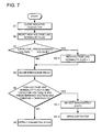
- Step S1 the negative terminal contactor 3B is first closed by the contactor controlling circuit 14. Subsequently, in Step S2, a high-voltage line normality flag is reset that indicates that the high-voltage line is in the normal state. In this step, the high-voltage line normality flag is reset to 0 (zero). Subsequently, in Step S3, the voltage detecting circuit 12 detects the capacitor voltage, and compares the detected capacitor voltage with the predetermined voltage.
- the predetermined voltage is a threshold voltage value for determining whether the electric charge is still stored in the vehicle-side capacitor 21.
- the predetermined voltage can be set at an arbitrary value, e.g., a value in the range of 10% to 80%.
- the predetermined voltage is set at 50% of the battery voltage (BV/2).
- the determination circuit 13 determines whether the capacitor voltage CV is larger than 50% of the battery voltage BV. If the capacitor voltage CV is not larger than 50% of the battery voltage BV, the procedure goes to Step S4. On the other hand, if the capacitor voltage CV is larger than 50% of the battery voltage BV, the procedure goes to Step S3-1.
- Step S3-1 the high-voltage line normality flag is set to 1 (one) for indicating the normal state.
- Step S4 both, the capacitor voltage is thus detected with both the positive and negative terminal contactors 3A and 3B being opened. Accordingly, it is determined whether electric charge is still stored in the vehicle-side capacitor 21. As shown in Fig. 5 , if the capacitor voltage is detected, it is determined that the vehicle-side load 20 is connected. At this time, the connected state is confirmed. Accordingly, the voltage line normality flag can be set at 1 (one).
- Step S4 the precharge relay 6 is closed by the relay controlling circuit 15 so that the procedure performs the precharge operation.
- Step S5 non-contact state determining operation is performed where the determination circuit 13 determines whether the increase of the capacitor voltage agrees with non-contact state determining conditions.
- the capacitor voltage is detected again by the voltage detecting circuit 12 so that the detected capacitor voltage is compared with a second predetermined voltage.
- a range of 100% ⁇ 20% (i.e., 80% to 120%) of the battery voltage BV is employed as the second predetermined voltage.
- the range as said second predetermined voltage has upper and lower limit values, even if the voltage detecting circuit malfunctions, it can be determined that the detected value overflows. As a result, it is possible prevent that it is wrongly detected that the detected capacitor voltage reaches the full range.
- a current value be additionally included in the non-contact state determining conditions. Current does not flow in the non-contact state. For this reason, when a current value detected by the current detecting circuit 11 is compared with a threshold current value, if the current value is lower than the threshold current value, the non-contact state can be detected.
- the current value can be set at 1.5 A.
- the non-contact state determination conditions it is determined whether all the following conditions are satisfied as the non-contact state determination conditions.
- the first condition it is determined whether the high-voltage line normality flag is 0 (zero).
- the second condition it is determined whether the capacitor voltage falls within the predetermined range.
- the third condition it is determined whether the current value detected by the current detecting circuit 11 is lower than the predetermined current threshold value.
- the non-contact state where disconnection or the like occurs, the current does not flow into the vehicle-side capacitor 21. Accordingly, the capacitor voltage immediately sharply increases, and the current does not flow. As a result, the current value is low. In this case, in order to properly detect the non-contact state, the non-contact state is detected if all the above three conditions are satisfied.
- a plurality of non-contact state determining operations be performed periodically at a predetermined period of time. In this case, if the non-contact state is detected continuously for a predetermined number of times, it is concluded that the non-contact state is detected. In this embodiment, the non-contact state determining operations is performed periodically at an interval of 10 ms. If the non-contact state is detected continuously for five times, the procedure goes to Step S5-1. In Step S5-1, the determination circuit 13 concludes the non-contact state, and confirms high-voltage line error. Subsequently, the procedure goes to Step S5-2 where the contactor is turned OFF.
- Step 5 if the non-contact state determining conditions are not satisfied in Step 5, the procedure goes to Step S6 where the determination circuit 13 detects the connected state.
- the precharge operation is continued. That is, predetermined processes of precharge operation are sequentially performed such as process for closing the positive terminal contactor 3A, and process for turning the precharge relay 6 OFF.
- the negative terminal contactor 3B and the precharge relay 6 are not simultaneously closed, but as shown in the timing charts of Figs. 4 to 6 , after the negative terminal contactor 3B is closed, the precharge relay 6 is closed at delayed timing. Accordingly, it is possible distinguish the capacitor voltage produced by electric charge stored in the vehicle-side capacitor 21 from the capacitor voltage caused by the non-contact state. That is, in the case of the non-contact state, as shown in Fig. 6 , when both the negative terminal contactor 3B and the precharge relay 6 are closed, the battery voltage of the driving battery 1 will be detected by the voltage detecting circuit 12. On the other hand, in the case where the electric charge is still stored in the vehicle-side capacitor 21, as shown in Fig.
- the capacitor voltage of the vehicle-side capacitor 21 can be detected by the voltage detecting circuit 12. Since the negative terminal contactor 3B and the precharge relay 6 are closed at different timing, it is possible distinguish the capacitor voltage produced by electric charge stored in the vehicle-side capacitor from the capacitor voltage caused by the non-contact state. Therefore, it is possible to properly detect the non-contact state. It is noted that it is enough for the delayed time of the precharge relay 6 closing from the negative terminal contactor 3B closing to allow the voltage detecting circuit 12 to detect the voltage.
- the delayed time can be set at arbitrary time, e.g., a value in the range of 5 to 50 ms.
- the determination circuit 13 can detect the connected state of the vehicle-side load 20 by using the voltage detecting circuit 12 and the current detecting circuit 11, which are existing circuits.
- the vehicle power supply device can be directly fastened to the vehicle-side load by screws and the like without using a complicated connector having an interlock mechanism. Therefore, there is an advantage that the vehicle power supply device can be simply connected to the vehicle-side load.
- voltage variation is monitored at the beginning of precharge operation, it is possible to quickly and properly detect the connected state.
- the negative terminal contactor 3B is closed when the capacitor voltage is detected in the aforementioned precharge operation, in the case where the negative connection line of the voltage detecting circuit 12 is connected to the negative terminal of the driving battery 1, the closing operation of the negative terminal contactor 3B can be eliminated.
- the contactors are arranged on the positive and negative terminal sides in the foregoing embodiment, the present invention is not limited to this construction. The contactor may be provided only on the positive or negative terminal side.
- the vehicle power supply device can be used as a battery system for vehicles.
- the power supply device can be installed on electric vehicles such as hybrid cars that are driven by both an engine and a motor, and electric vehicles that are driven only by a motor.
- the power supply device can be used as a power supply device for these types of vehicles.
- Fig. 8 is a block diagram showing an exemplary hybrid car that is driven both by an engine and an electric motor, and includes the power supply device.
- the illustrated vehicle HV with the power supply device includes an electric motor 93 and an engine 96 that drive the vehicle HV, a battery system 100B that supplies electric power to the electric motor 93, and an electric generator 94 that charges batteries of the battery system 100B.
- the battery system 100B is connected to the electric motor 93 and the electric generator 94 via a DC/AC inverter 95.
- the vehicle HV is driven both by the electric motor 93 and the engine 96 with the batteries of the battery system 100B being charged/discharged.
- the electric motor 93 is energized with electric power and drives the vehicle in a poor engine efficiency range, e.g., in acceleration or in a low speed range.
- the electric motor 93 is energized by electric power is supplied from the battery system 100B.
- the electric generator 94 is driven by the engine 96 or by regenerative braking when users brake the vehicle so that the batteries of the battery system 100B are charged.
- Fig. 9 shows an exemplary electric vehicle that is driven only by an electric motor, and includes the power supply device.
- the illustrated vehicle EV with the power supply device includes an electric motor 93 that drives the vehicle EV, a battery system 100C that supplies electric power to the electric motor 93, and an electric generator 94 that charges batteries of the battery system 100C.
- the electric motor 93 is energized by electric power that is supplied from the battery system 100C.
- the electric generator 94 can be driven by vehicle EV regenerative braking so that the batteries of the battery system 100C are charged.
- the power supply device can be used not only as power supply of mobile unit such as vehicle but also as stationary power storage.
- stationary power storage devices can be provided by an electric power system for home use or plant use that is charged with solar electric power or with midnight electric power and is discharged when necessary, a power supply for street lights that is charged with solar electric power during the daytime and is discharged during the nighttime, or a backup power supply for signal lights that drives signal lights in the event of a power failure.
- Fig. 10 shows a circuit diagram according to this embodiment.
- This illustrated power supply device 100 includes battery units 82 each of which includes a plurality of battery packs 81 that are connected to each other. In each of battery packs 81, a plurality of battery cells are connected to each other in serial and/or in parallel.
- the battery packs 81 are controlled by a power supply controller 84.
- the power supply device 100 After the battery units 82 are charged by a charging power supply CP, the power supply device 100 drives a load LD.
- the power supply device 100 has a charging mode and a discharging mode.
- the Load LD and the charging power supply CP are connected to the power supply device 100 through a discharging switch DS and a charging switch CS, respectively.
- the discharging switch DS and the charging operation switch CS are turned ON/OFF by the power supply controller 84 of the power supply device 100.
- the power supply controller 84 turns charging operation switch CS ON, and turns the discharging switch DS OFF so that the power supply device 100 can be charged by the charging power supply CP.
- the power supply controller 84 turns the charging operation switch CS OFF, and turns the discharging switch DS ON.
- operation is switched from the charging mode to the discharging mode so that the power supply device 100 can be discharged to supply power to the load LD.
- the charging operation switch CS may be turned ON, while the discharging switch DS may be turned ON so that the load LD can be supplied with electric power while the power supply device 100 can be charged.
- the load LD driven by the power supply device 100 is connected to the power supply device 100 through the discharging switch DS.
- the power supply controller 84 turns the discharging switch DS ON so that the power supply device 100 is connected to the load LD.
- the load LD is driven with electric power from the power supply device 100.
- Switching elements such as FET can be used as the discharging switch DS.
- the discharging switch DS is turned ON/OFF by the power supply controller 84 of the power supply device 100.
- the power supply controller 84 includes a communication interface for communicating with an external device. In the power supply device according to the embodiment shown in Fig.
- the power supply controller is connected to a host device HT based on existing communications protocols such as UART and RS-232C.
- the power supply device may include a user interface that allows users to operate the electric power system if necessary.
- Each of the battery packs 81 includes signal terminals and power supply terminals.
- the signal terminals include a pack input/output terminal DI, a pack abnormality output terminal DA, and a pack connection terminal DO.
- the pack input/output terminal DI serves as a terminal for providing/receiving signals to/from other battery packs and the power supply controller 84.
- the pack connection terminal DO serves as a terminal for providing/receiving signals to/from other battery packs as slave packs.
- the pack abnormality output terminal DA serves as a terminal for providing an abnormality signal of the battery pack to the outside.
- the power supply terminal is a terminal for connecting one of the battery packs 81 to another battery pack in series or in parallel.
- the battery units 82 are connected to an output line OL through parallel connection switched 85, and are connected in parallel to each other.
- a power supply device and a method for detecting the non-contact state of a load connected to a power supply device according to the present invention can be suitably applied to power supple devices of plug-in hybrid vehicles and hybrid electric vehicles that can switch between the EV drive mode and the HEV drive mode, electric vehicles, and the like. It should be apparent to those with an ordinary skill in the art that while various preferred embodiments of the invention have been shown and described, it is contemplated that the invention is not limited to the particular embodiments disclosed, which are deemed to be merely illustrative of the inventive concepts and should not be interpreted as limiting the scope of the invention, and which are suitable for all modifications and changes falling within the scope of the invention as defined in the appended claims.
Landscapes
- Engineering & Computer Science (AREA)
- Power Engineering (AREA)
- Transportation (AREA)
- Mechanical Engineering (AREA)
- Life Sciences & Earth Sciences (AREA)
- Sustainable Development (AREA)
- Sustainable Energy (AREA)
- Electric Propulsion And Braking For Vehicles (AREA)
- Charge And Discharge Circuits For Batteries Or The Like (AREA)
- Keying Circuit Devices (AREA)
Applications Claiming Priority (1)
| Application Number | Priority Date | Filing Date | Title |
|---|---|---|---|
| JP2010043132A JP5575506B2 (ja) | 2010-02-26 | 2010-02-26 | 車両用電源装置及びこの電源装置を備える車両 |
Publications (1)
| Publication Number | Publication Date |
|---|---|
| EP2361799A2 true EP2361799A2 (fr) | 2011-08-31 |
Family
ID=44208465
Family Applications (1)
| Application Number | Title | Priority Date | Filing Date |
|---|---|---|---|
| EP20110001585 Withdrawn EP2361799A2 (fr) | 2010-02-26 | 2011-02-25 | Dispositif d'alimentation électrique et procédé de détection d'état sans contact de charge connectée à un dispositif d'alimentation électrique |
Country Status (4)
| Country | Link |
|---|---|
| US (1) | US8575940B2 (fr) |
| EP (1) | EP2361799A2 (fr) |
| JP (1) | JP5575506B2 (fr) |
| CN (1) | CN102166959A (fr) |
Cited By (7)
| Publication number | Priority date | Publication date | Assignee | Title |
|---|---|---|---|---|
| FR2978879A1 (fr) * | 2011-08-02 | 2013-02-08 | Renault Sa | Procede de diagnostic d'un court-circuit dans un ensemble electrique d'un vehicule automobile comprenant une composante capacitive et dispositif de diagnostic |
| WO2014202879A1 (fr) | 2013-06-18 | 2014-12-24 | Renault S.A.S | Procédé de gestion d'une charge alimentée par un convertisseur lui-même alimenté par une batterie, et système correspondant |
| EP2695762A3 (fr) * | 2012-08-09 | 2017-11-01 | GS Yuasa International Ltd. | Appareil de stockage électrique et appareil de commutation de trajet de puissance |
| EP3385108A4 (fr) * | 2016-07-15 | 2019-02-13 | LG Chem, Ltd. | Système et procédé permettant d'empêcher une ouverture anormale de contacteur par le biais d'une détection de fonctionnement en temps réel |
| CN111301173A (zh) * | 2020-04-09 | 2020-06-19 | 宁德时代新能源科技股份有限公司 | 负载接入检测方法、开关电路与电池管理系统 |
| CN114641407A (zh) * | 2019-11-18 | 2022-06-17 | 纬湃科技有限责任公司 | 用于控制具有电动机的车辆的电池和接头之间的连接的方法和装置 |
| FR3132599A1 (fr) * | 2022-02-04 | 2023-08-11 | Psa Automobiles Sa | Surveillance d’un circuit de précharge d’un circuit d’interface d’un système |
Families Citing this family (62)
| Publication number | Priority date | Publication date | Assignee | Title |
|---|---|---|---|---|
| US9252631B2 (en) * | 2011-06-08 | 2016-02-02 | Andrew V. Latham | Data center battery enhancement method and system |
| US8941264B2 (en) * | 2011-06-20 | 2015-01-27 | Bae Systems Information And Electronic Systems Integration Inc. | Apparatus for bi-directional power switching in low voltage vehicle power distribution systems |
| US20130026992A1 (en) * | 2011-07-25 | 2013-01-31 | Joy Ride Technology Co., Ltd. | Rechargeable battery device, and power supplying system incorporating the same |
| JP5502918B2 (ja) * | 2011-10-13 | 2014-05-28 | 株式会社日本自動車部品総合研究所 | 組電池の充放電装置 |
| KR101241226B1 (ko) * | 2011-10-27 | 2013-03-13 | 현대자동차주식회사 | 친환경 차량의 메인 릴레이 모니터링장치 및 방법 |
| US9341665B2 (en) * | 2012-04-18 | 2016-05-17 | Lear Corporation | Method and apparatus for high voltage isolation monitor for a vehicle |
| US9283852B2 (en) * | 2012-05-09 | 2016-03-15 | Schneider Electric USA, Inc. | Diagnostic receptacle for electric vehicle supply equipment |
| GB2502053B (en) * | 2012-05-14 | 2014-09-24 | Nicoventures Holdings Ltd | Electronic smoking device |
| GB2502055A (en) * | 2012-05-14 | 2013-11-20 | Nicoventures Holdings Ltd | Modular electronic smoking device |
| JP2013248971A (ja) * | 2012-05-31 | 2013-12-12 | Honda Motor Co Ltd | 電動車両における電力供給装置 |
| JP6365725B2 (ja) * | 2012-08-09 | 2018-08-01 | 株式会社Gsユアサ | 蓄電装置及び電力経路開閉装置 |
| GB2507103A (en) | 2012-10-19 | 2014-04-23 | Nicoventures Holdings Ltd | Electronic inhalation device |
| GB2507104A (en) | 2012-10-19 | 2014-04-23 | Nicoventures Holdings Ltd | Electronic inhalation device |
| KR101428262B1 (ko) * | 2012-12-10 | 2014-08-07 | 현대자동차주식회사 | 차량 배터리 전원 제어 장치 |
| US9190682B2 (en) * | 2013-01-04 | 2015-11-17 | Lilliputian Systems, Inc. | Fuel cell system having a safety mode |
| CN103078386A (zh) * | 2013-01-25 | 2013-05-01 | 贠爱茹 | 一种集成式电源管理系统 |
| DE102013202812A1 (de) * | 2013-02-21 | 2014-08-21 | Robert Bosch Gmbh | Steuerschaltung |
| EP2969638A1 (fr) | 2013-03-11 | 2016-01-20 | Volvo Truck Corporation | Procédé et agencement pour le fonctionnement d'un véhicule électrique hybride |
| JP6107283B2 (ja) * | 2013-03-25 | 2017-04-05 | 三菱自動車工業株式会社 | 電源装置 |
| US9726725B2 (en) * | 2013-08-02 | 2017-08-08 | Jtekt Corporation | Power circuit abnormality detection method |
| JP6146332B2 (ja) * | 2013-09-11 | 2017-06-14 | トヨタ自動車株式会社 | リレーの固着判別システム |
| US9925878B2 (en) | 2013-09-26 | 2018-03-27 | Ford Global Technologies, Llc | Bus pre-charge control using a buck converter |
| GB2519101A (en) | 2013-10-09 | 2015-04-15 | Nicoventures Holdings Ltd | Electronic vapour provision system |
| US10107847B2 (en) * | 2014-03-25 | 2018-10-23 | Ford Global Technologies, Llc | Diagnostic method for contactor resistance failure |
| CN103995211A (zh) * | 2014-05-30 | 2014-08-20 | 长城汽车股份有限公司 | 车用高压系统的检测方法及系统 |
| CN104827910B (zh) * | 2014-07-14 | 2017-07-11 | 北汽福田汽车股份有限公司 | 电动汽车的高压系统控制方法、系统及具有其的车辆 |
| US9947497B2 (en) | 2014-09-30 | 2018-04-17 | Johnson Controls Technology Company | Integrated connector having sense and switching conductors for a relay used in a battery module |
| KR102296132B1 (ko) * | 2015-02-16 | 2021-08-31 | 삼성에스디아이 주식회사 | 배터리 팩 및 그의 구동방법 |
| US10114060B2 (en) | 2015-02-16 | 2018-10-30 | Continental Automotive Systems, Inc. | Negative battery main contactor status determination |
| KR102285145B1 (ko) * | 2015-05-11 | 2021-08-04 | 삼성에스디아이 주식회사 | 전기 이동 수단 및 그 제어 방법 |
| GB2540135B (en) | 2015-07-01 | 2021-03-03 | Nicoventures Holdings Ltd | Electronic aerosol provision system |
| KR102436418B1 (ko) * | 2015-07-02 | 2022-08-25 | 삼성에스디아이 주식회사 | 배터리 팩의 전류 측정 방법 |
| US10300791B2 (en) * | 2015-12-18 | 2019-05-28 | Ge Global Sourcing Llc | Trolley interfacing device having a pre-charging unit |
| US9931949B2 (en) * | 2016-02-26 | 2018-04-03 | Ford Global Technologies, Llc | Fault detection in a multi-high voltage bus system |
| FR3048387B1 (fr) * | 2016-03-02 | 2019-06-21 | Alstom Transport Technologies | Installation amelioree de recharge par conduction d'un vehicule |
| US20200097058A1 (en) * | 2016-03-09 | 2020-03-26 | Razer (Asia-Pacific) Pte. Ltd. | Computing devices, power supply devices, methods for controlling a computing device, and methods for controlling a power supply device |
| EP3272236B1 (fr) * | 2016-07-22 | 2021-06-16 | Fontem Holdings 1 B.V. | Dispositif à fumer électronique |
| US10384627B2 (en) * | 2016-08-09 | 2019-08-20 | Ford Global Technologies, Llc | Pre-charging load using main contactor coil |
| US10516189B2 (en) * | 2016-11-15 | 2019-12-24 | Ford Global Technologies, Llc | High voltage bus contactor fault detection |
| KR102371597B1 (ko) * | 2017-04-06 | 2022-03-07 | 현대자동차주식회사 | 차량의 급속충전 제어 장치 및 방법 |
| CN108859762A (zh) * | 2017-05-08 | 2018-11-23 | 华晨汽车集团控股有限公司 | 一种新能源车用动力电池继电器的控制系统及检测方法 |
| JP6885559B2 (ja) * | 2017-06-12 | 2021-06-16 | 株式会社サムソン | リレーのセルフチェックを行う制御装置 |
| CN107253439B (zh) * | 2017-06-29 | 2019-09-24 | 科力远混合动力技术有限公司 | 混合动力汽车高压系统的预充电控制电路及控制方法 |
| JP6545230B2 (ja) * | 2017-08-31 | 2019-07-17 | 本田技研工業株式会社 | 車両の電源システム |
| CN109581090B (zh) * | 2017-09-28 | 2021-02-23 | 比亚迪股份有限公司 | 主控预充器的寿命测试装置和寿命测试系统 |
| GB201721821D0 (en) | 2017-12-22 | 2018-02-07 | Nicoventures Holdings Ltd | Electronic aerosol provision system |
| CN109177761A (zh) * | 2018-09-28 | 2019-01-11 | 吉林大学 | 一种电动汽车非接触式充电装置 |
| JP6793700B2 (ja) * | 2018-10-16 | 2020-12-02 | 矢崎総業株式会社 | 車両用電源回路 |
| JP7189009B2 (ja) * | 2018-12-25 | 2022-12-13 | トヨタ自動車株式会社 | 車両の制御装置 |
| CN110601601B (zh) * | 2019-08-30 | 2021-05-11 | 广东志高暖通设备股份有限公司 | 预充电控制电路及充电单元、空调 |
| CN112255577A (zh) * | 2019-10-30 | 2021-01-22 | 蜂巢能源科技有限公司 | 用于检测接触器粘连的方法及系统 |
| CN113125872B (zh) * | 2019-12-31 | 2022-10-18 | 比亚迪股份有限公司 | 一种充放电电路的检测方法、检测系统、存储介质及车辆 |
| CN111267621B (zh) * | 2020-03-31 | 2023-05-30 | 郑州智驱科技有限公司 | 一种电动汽车预充保护方法及系统 |
| KR102646734B1 (ko) * | 2020-11-26 | 2024-03-13 | 엘지이노텍 주식회사 | 직류/직류 컨버터 및 이의 제어 방법 |
| US11400831B1 (en) | 2021-01-15 | 2022-08-02 | Ford Global Technologies, Llc | Pre-charge via bi-directional DC/DC converter and auxiliary battery |
| KR20230011796A (ko) * | 2021-07-14 | 2023-01-25 | 주식회사 엘지에너지솔루션 | 배터리 장치, 배터리 관리 시스템 및 프리차지 방법 |
| CN113899954B (zh) * | 2021-08-31 | 2024-04-09 | 博科能源系统(深圳)有限公司 | 负载检测方法及电池管理系统 |
| JP7767816B2 (ja) * | 2021-10-01 | 2025-11-12 | マツダ株式会社 | 車両のコンタクタ故障判定装置 |
| JP7613415B2 (ja) * | 2022-04-27 | 2025-01-15 | トヨタ自動車株式会社 | 状態検出システムおよび接続ケーブル |
| CN115424375B (zh) * | 2022-08-29 | 2024-12-31 | 长园共创电力安全技术股份有限公司 | 一种智能互联的接地线防误系统及其地线挂接、拆除方法 |
| KR20240037089A (ko) * | 2022-09-14 | 2024-03-21 | 현대자동차주식회사 | 직류 컨버터, 이를 포함하는 차량 및 그들의 제어 방법 |
| US20250170895A1 (en) * | 2023-11-28 | 2025-05-29 | Fisker Inc. | Intelligent high voltage interlock loop with individualized detection of connector connectivity |
Citations (1)
| Publication number | Priority date | Publication date | Assignee | Title |
|---|---|---|---|---|
| JP2006216516A (ja) | 2005-02-07 | 2006-08-17 | Sanyo Electric Co Ltd | 車両用の電源装置と電源装置の溶着検出方法 |
Family Cites Families (17)
| Publication number | Priority date | Publication date | Assignee | Title |
|---|---|---|---|---|
| JP3487952B2 (ja) * | 1995-04-14 | 2004-01-19 | 株式会社日立製作所 | 電気自動車の駆動装置及び駆動制御方法 |
| TW472426B (en) * | 1998-10-06 | 2002-01-11 | Hitachi Ltd | Battery apparatus and control system therefor |
| JP2001327001A (ja) * | 2000-05-11 | 2001-11-22 | Toyota Motor Corp | ハイブリッド車両におけるシステムリレーの診断装置およびその方法 |
| JP3966702B2 (ja) * | 2001-08-31 | 2007-08-29 | 松下電器産業株式会社 | バッテリ制御装置 |
| JP3706585B2 (ja) * | 2002-02-19 | 2005-10-12 | 三洋電機株式会社 | ハイブリッドカーのバッテリ状態表示方法とバッテリ状態表示装置 |
| JP4604485B2 (ja) * | 2003-12-25 | 2011-01-05 | トヨタ自動車株式会社 | 電源系統の異常検知装置 |
| JP2005354789A (ja) * | 2004-06-09 | 2005-12-22 | Hitachi Ltd | 電気車の制御装置 |
| JP4565963B2 (ja) * | 2004-10-27 | 2010-10-20 | ダイハツ工業株式会社 | 故障検出処理装置 |
| JP4622583B2 (ja) * | 2005-03-01 | 2011-02-02 | トヨタ自動車株式会社 | 故障診断装置および車両 |
| JP4529851B2 (ja) * | 2005-09-20 | 2010-08-25 | トヨタ自動車株式会社 | 電源回路の異常検知装置 |
| JP4749190B2 (ja) * | 2006-03-24 | 2011-08-17 | 三洋電機株式会社 | 車両用の電源装置とこの電源装置のコンタクターの溶着を判別する溶着検出方法 |
| JP4678374B2 (ja) * | 2007-01-04 | 2011-04-27 | トヨタ自動車株式会社 | 負荷装置の制御装置、および車両 |
| US7768237B2 (en) * | 2007-05-11 | 2010-08-03 | Gm Global Technology Operations, Inc. | Simplified automatic discharge function for vehicles |
| JP2009038925A (ja) * | 2007-08-02 | 2009-02-19 | Sanyo Electric Co Ltd | 車両用の電源装置とその制御方法 |
| JP5193660B2 (ja) * | 2008-04-03 | 2013-05-08 | 株式会社日立製作所 | 電池モジュール及びそれを備えた蓄電装置並びに電機システム |
| JP5106272B2 (ja) * | 2008-06-30 | 2012-12-26 | パナソニック株式会社 | 劣化判定回路、電源装置、及び二次電池の劣化判定方法 |
| US8049372B2 (en) * | 2008-07-01 | 2011-11-01 | GM Global Technology Operations LLC | Precharging a high-voltage bus using a voltage-regulated power supply |
-
2010
- 2010-02-26 JP JP2010043132A patent/JP5575506B2/ja active Active
-
2011
- 2011-02-25 EP EP20110001585 patent/EP2361799A2/fr not_active Withdrawn
- 2011-02-25 CN CN2011100482354A patent/CN102166959A/zh active Pending
- 2011-02-25 US US13/035,143 patent/US8575940B2/en active Active
Patent Citations (1)
| Publication number | Priority date | Publication date | Assignee | Title |
|---|---|---|---|---|
| JP2006216516A (ja) | 2005-02-07 | 2006-08-17 | Sanyo Electric Co Ltd | 車両用の電源装置と電源装置の溶着検出方法 |
Cited By (14)
| Publication number | Priority date | Publication date | Assignee | Title |
|---|---|---|---|---|
| WO2013017779A3 (fr) * | 2011-08-02 | 2013-12-27 | Renault Sas | Procédé de diagnostic d'un court-circuit dans un ensemble électrique d'un véhicule automobile comprenant une composante capacitive et dispositif de diagnostic |
| FR2978879A1 (fr) * | 2011-08-02 | 2013-02-08 | Renault Sa | Procede de diagnostic d'un court-circuit dans un ensemble electrique d'un vehicule automobile comprenant une composante capacitive et dispositif de diagnostic |
| EP2695762A3 (fr) * | 2012-08-09 | 2017-11-01 | GS Yuasa International Ltd. | Appareil de stockage électrique et appareil de commutation de trajet de puissance |
| US10298011B2 (en) | 2012-08-09 | 2019-05-21 | Gs Yuasa International Ltd. | Electric storage apparatus and power path switch apparatus |
| WO2014202879A1 (fr) | 2013-06-18 | 2014-12-24 | Renault S.A.S | Procédé de gestion d'une charge alimentée par un convertisseur lui-même alimenté par une batterie, et système correspondant |
| EP3385108A4 (fr) * | 2016-07-15 | 2019-02-13 | LG Chem, Ltd. | Système et procédé permettant d'empêcher une ouverture anormale de contacteur par le biais d'une détection de fonctionnement en temps réel |
| CN114641407B (zh) * | 2019-11-18 | 2023-08-22 | 纬湃科技有限责任公司 | 用于控制具有电动机的车辆的电池和接头之间的连接的方法和装置 |
| US12024035B2 (en) | 2019-11-18 | 2024-07-02 | Vitesco Technologies GmbH | Method and device for controlling a connection between a battery and a socket of an electric motor vehicle |
| CN114641407A (zh) * | 2019-11-18 | 2022-06-17 | 纬湃科技有限责任公司 | 用于控制具有电动机的车辆的电池和接头之间的连接的方法和装置 |
| CN111301173A (zh) * | 2020-04-09 | 2020-06-19 | 宁德时代新能源科技股份有限公司 | 负载接入检测方法、开关电路与电池管理系统 |
| CN111301173B (zh) * | 2020-04-09 | 2023-12-15 | 宁德时代新能源科技股份有限公司 | 负载接入检测方法、开关电路与电池管理系统 |
| US12009682B2 (en) | 2020-04-09 | 2024-06-11 | Contemporary Amperex Technology Co., Limited | Load access detection method, switch circuit, and battery management system |
| EP3922503A4 (fr) * | 2020-04-09 | 2022-03-23 | Contemporary Amperex Technology Co., Limited | Procédé de détection d'accès à la charge, circuit de commutation et système de gestion de batterie |
| FR3132599A1 (fr) * | 2022-02-04 | 2023-08-11 | Psa Automobiles Sa | Surveillance d’un circuit de précharge d’un circuit d’interface d’un système |
Also Published As
| Publication number | Publication date |
|---|---|
| US20110210746A1 (en) | 2011-09-01 |
| CN102166959A (zh) | 2011-08-31 |
| US8575940B2 (en) | 2013-11-05 |
| JP5575506B2 (ja) | 2014-08-20 |
| JP2011182530A (ja) | 2011-09-15 |
Similar Documents
| Publication | Publication Date | Title |
|---|---|---|
| US8575940B2 (en) | Power supply device and method for detecting non-contact state of load connected to power supply device | |
| US10804575B2 (en) | Secondary battery system and method for diagnosing abnormality in battery pack | |
| US9956882B2 (en) | Electric power storage system | |
| CN110226275B (zh) | 电气系统和用于使电气系统通电的方法 | |
| CN1770586B (zh) | 电源控制器、电动车和电池控制单元 | |
| US10093190B2 (en) | Charging control device | |
| EP2509186B1 (fr) | Appareil d'alimentation électrique et son procédé de contrôle | |
| CN105324274B (zh) | 车辆用电源系统 | |
| US7768237B2 (en) | Simplified automatic discharge function for vehicles | |
| EP2940827B1 (fr) | Dispositif d'alimentation électrique utilisant un véhicule électrique | |
| EP2607178B1 (fr) | Alimentation électrique pour alimenter une charge électrique d'un véhicule | |
| CN102811887B (zh) | 车辆用电源装置 | |
| US8513918B2 (en) | Vehicle battery control system having a voltage sensor that measures a voltage between a contactor and an inverter equipment | |
| EP2413453A2 (fr) | Dispositif d'alimentation doté d'un circuit de préchargement pour charger le disjoncteur | |
| US20140343776A1 (en) | Power supply system for vehicle | |
| EP2671761A1 (fr) | Dispositif de gestion d'alimentation électrique | |
| CN104823347B (zh) | 蓄电系统 | |
| CN103998946B (zh) | 监视系统和车辆 | |
| JP2012182892A (ja) | 電源装置 | |
| CN118613389A (zh) | 用于电动交通工具的车载电气系统 | |
| JP2015077036A (ja) | 車両の電源システム、及び電源ユニット | |
| CN114475489A (zh) | 汽车的电源系统及汽车、汽车的电源系统的控制方法 | |
| JP2014223003A (ja) | 蓄電システム | |
| CN114788120A (zh) | 车载电池系统 | |
| CN118953060A (zh) | 车辆电机控制方法、装置、存储介质及电子装置 |
Legal Events
| Date | Code | Title | Description |
|---|---|---|---|
| PUAI | Public reference made under article 153(3) epc to a published international application that has entered the european phase |
Free format text: ORIGINAL CODE: 0009012 |
|
| AK | Designated contracting states |
Kind code of ref document: A2 Designated state(s): AL AT BE BG CH CY CZ DE DK EE ES FI FR GB GR HR HU IE IS IT LI LT LU LV MC MK MT NL NO PL PT RO RS SE SI SK SM TR |
|
| AX | Request for extension of the european patent |
Extension state: BA ME |
|
| STAA | Information on the status of an ep patent application or granted ep patent |
Free format text: STATUS: THE APPLICATION IS DEEMED TO BE WITHDRAWN |
|
| 18D | Application deemed to be withdrawn |
Effective date: 20150901 |