EP2361815B1 - Couplage actif entre un train d'atterrissage et une caisse dans un véhicule - Google Patents
Couplage actif entre un train d'atterrissage et une caisse dans un véhicule Download PDFInfo
- Publication number
- EP2361815B1 EP2361815B1 EP11154699.0A EP11154699A EP2361815B1 EP 2361815 B1 EP2361815 B1 EP 2361815B1 EP 11154699 A EP11154699 A EP 11154699A EP 2361815 B1 EP2361815 B1 EP 2361815B1
- Authority
- EP
- European Patent Office
- Prior art keywords
- adjustment
- vehicle
- setpoint value
- frequency range
- actuator device
- Prior art date
- Legal status (The legal status is an assumption and is not a legal conclusion. Google has not performed a legal analysis and makes no representation as to the accuracy of the status listed.)
- Active
Links
- 230000008878 coupling Effects 0.000 title description 6
- 238000010168 coupling process Methods 0.000 title description 6
- 238000005859 coupling reaction Methods 0.000 title description 6
- 230000001133 acceleration Effects 0.000 claims description 70
- 230000000694 effects Effects 0.000 claims description 26
- 238000000034 method Methods 0.000 claims description 26
- 230000009471 action Effects 0.000 claims description 17
- 230000008030 elimination Effects 0.000 claims description 10
- 238000003379 elimination reaction Methods 0.000 claims description 10
- 238000001514 detection method Methods 0.000 description 30
- 239000000725 suspension Substances 0.000 description 16
- 230000008901 benefit Effects 0.000 description 5
- 230000002349 favourable effect Effects 0.000 description 5
- 238000006073 displacement reaction Methods 0.000 description 4
- 238000001914 filtration Methods 0.000 description 4
- 230000001419 dependent effect Effects 0.000 description 3
- 230000010354 integration Effects 0.000 description 3
- 230000006872 improvement Effects 0.000 description 2
- 238000009434 installation Methods 0.000 description 2
- 230000010355 oscillation Effects 0.000 description 2
- 230000009467 reduction Effects 0.000 description 2
- 230000004044 response Effects 0.000 description 2
- 230000003068 static effect Effects 0.000 description 2
- 238000007096 Glaser coupling reaction Methods 0.000 description 1
- 230000000712 assembly Effects 0.000 description 1
- 238000000429 assembly Methods 0.000 description 1
- 230000008094 contradictory effect Effects 0.000 description 1
- 238000005516 engineering process Methods 0.000 description 1
- 239000003112 inhibitor Substances 0.000 description 1
- 230000005764 inhibitory process Effects 0.000 description 1
- 238000013178 mathematical model Methods 0.000 description 1
- 230000007246 mechanism Effects 0.000 description 1
- 230000007935 neutral effect Effects 0.000 description 1
Images

Classifications
-
- B—PERFORMING OPERATIONS; TRANSPORTING
- B61—RAILWAYS
- B61F—RAIL VEHICLE SUSPENSIONS, e.g. UNDERFRAMES, BOGIES OR ARRANGEMENTS OF WHEEL AXLES; RAIL VEHICLES FOR USE ON TRACKS OF DIFFERENT WIDTH; PREVENTING DERAILING OF RAIL VEHICLES; WHEEL GUARDS, OBSTRUCTION REMOVERS OR THE LIKE FOR RAIL VEHICLES
- B61F5/00—Constructional details of bogies; Connections between bogies and vehicle underframes; Arrangements or devices for adjusting or allowing self-adjustment of wheel axles or bogies when rounding curves
- B61F5/02—Arrangements permitting limited transverse relative movements between vehicle underframe or bolster and bogie; Connections between underframes and bogies
- B61F5/22—Guiding of the vehicle underframes with respect to the bogies
Definitions
- the present invention relates to a method for adjusting a force effect and / or a relative position between a chassis and a car body of a vehicle, in particular a rail vehicle, in which acts on a force acting between the chassis, in particular a chassis frame of the chassis, and the car body actuator / or a relative position between the chassis and the car body is set in a plane of action, wherein the plane of action is defined by a vehicle longitudinal direction and a vehicle transverse direction of the vehicle and the adjustment of the force and / or the relative position in response to a Einstellvorgabe to implement a predetermined setting concept for the force effect and / or the relative position takes place, the adjustment of the force effect and / or the relative position being dependent on at least two different setting specifications for at least two presettable differences ed adjustment concepts.
- the present invention furthermore relates to a corresponding vehicle and to a control device which is suitable for carrying out the method according to the invention.
- the car body In rail vehicles - but also in other vehicles - the car body is usually supported by one or more spring stages on one or more chassis (for example, wheel units with pairs of wheels or sets of wheels, bogies, etc.).
- chassis for example, wheel units with pairs of wheels or sets of wheels, bogies, etc.
- driving dynamic requirements are placed on such chassis. These include, among other things, the demand for quiet and stable vehicle running, high driving safety and high comfort and low road load.
- the present invention is therefore based on the object to provide a method or a vehicle of the type mentioned above, which does not have the above-mentioned disadvantages or at least to a lesser extent and in particular in a simple way in a compact, space-saving design a high Level of comfort for the passengers with favorable wear characteristics allows.
- the present invention solves this problem starting from a method according to the preamble of claim 1 by the features stated in the characterizing part of claim 1.
- the present invention solves this problem further starting from a vehicle according to the preamble of claim 11 by the features stated in the characterizing part of claim 11.
- the present invention is based on the technical teaching that allows a simple way in a compact, space-saving design a high degree of comfort for the passengers with favorable wear characteristics, if the adjustment of the force and / or the relative position in dependence on several different setting specifications for a plurality of different adjustment concepts, using as one of at least two adjustment specifications an angular acceleration adjustment preset of an angular acceleration adjustment concept relating to minimizing an angular acceleration of the chassis about a rotational axis parallel to a vehicle height direction in a predetermined angular acceleration frequency range.
- the present invention therefore relates to a defined by the features of the above claim 1 method for adjusting a force effect and / or a relative position between a chassis and a car body of a vehicle, in particular a rail vehicle, in which one between the chassis and the Car body acting actuator means a force and / or a relative position between the chassis and the car body is set in a plane of action, wherein the plane of action by a vehicle longitudinal direction and a vehicle transverse direction of the vehicle is defined.
- the setting of the Force action and / or the relative position takes place as a function of an adjustment target for realizing a predefinable adjustment concept for the force effect and / or the relative position, the adjustment of the force effect and / or the relative position depending on at least two different setting specifications for at least two predetermined different adjustment concepts ,
- an angular acceleration adjustment preset of an angular acceleration adjustment concept is used, which involves minimizing, in particular substantially eliminating, an angular acceleration of the chassis about a rotational axis parallel to a vehicle height direction in a predetermined angular acceleration frequency range.
- the actuator device hereby integrates the function of a so-called roll damper or rotational inhibition, so that even at higher speeds (especially in the straight track) a stable vehicle running is achieved.
- the other adjustment concepts may be any (different) variants of the active engagement in the coupling between the chassis and the car body, via which the fulfillment of dynamic driving requirements (for example, the improvement of comfort, the reduction of wear on the chassis and / or on the track etc.) can be realized or ensured.
- any desired variables can be specified or used, adhering to the car body and / or on the chassis, a state adjusts, in which the pursued with the associated adjustment concept driving dynamic goal is achieved.
- any desired values with regard to one or more accelerations on the vehicle body and / or on the chassis, with respect to one or more relative movements between the car body and the chassis or even with respect to one or more force effects (forces and / or moments) can be specified.
- the described functional integration via the actuator device by taking into account different setting specifications of the different setting concepts can basically be done in any suitable manner.
- a control device based on a previously determined mathematical model of the vehicle (in particular a model of the coupling between the vehicle body and chassis) using the input variables required for the respective adjustment concept (often Measured values that are representative of accelerations, relative movements, force effects, etc.) and the different setting specifications directly generate at least one output variable that takes into account the actuator input as an input to drive a corresponding component of the actuator in a manner that takes into account all setting constraints ,
- an input variable for the actuator device is determined using each of the at least two different setting specifications and the actuator device is supplied.
- the setting of the force effect and / or the relative position then takes place as a function of the supplied input variables.
- a simple superimposition of the supplied input variables preferably takes place in order to realize the functional integration described, and thus therefore the joint consideration of all setting specifications.
- the adjustment of the force effect and / or the relative position takes place as a function of a sum of the supplied input variables.
- a first setting input of a first setting concept is used as one of the at least two setting instructions, the first setting concept minimizing, in particular substantially eliminating, first oscillations of the carbody relative to the chassis in the vehicle transverse direction in a first Frequency range.
- the first frequency range may be selected in any suitable manner.
- the first frequency range preferably extends above 0.5 Hz to 1.0 Hz.
- the first frequency range preferably extends from 1.0 Hz to 15 Hz, more preferably from 1.0 Hz to 6.0 Hz Way unwanted high-frequency transverse vibrations of the car body (which are perceived in this first frequency range of the passengers as particularly disturbing) significantly reduced, possibly even completely eliminated.
- the actuator device hereby integrates the function of a transverse damper, so that a particularly high ride comfort for the passengers is achieved.
- a first detection quantity is detected, which is representative of the transverse acceleration acting on the vehicle body in the vehicle transverse direction, while the first setting input used is a first desired value that is representative of a lateral acceleration desired value.
- the first detection amount and the first setpoint a first input for the Detected actuator and supplied to the actuator.
- an arbitrary value not equal to zero can be specified for the lateral acceleration setpoint, as long as this value is not perceived as disturbing by the passengers. It is preferably provided that the lateral acceleration be reduced as far as possible, so that the transverse acceleration target value preferably has the value zero in these cases.
- a second setting input of a second setting concept is used as one of the at least two setting instructions, the second setting concept minimizing, in particular substantially eliminating, a positional deviation of the carbody relative to the chassis in the vehicle transverse direction in a second Frequency range.
- the second frequency range can also be selected in any suitable manner.
- the second frequency range extends below 0.5 Hz to 2.0 Hz.
- the second frequency range extends from 0 Hz to 1.0 Hz, more preferably from 0 Hz to 0.5 Hz.
- the actuator device hereby integrates the function of a centering device.
- a second detection variable is detected, which is representative of the transverse deflection of the car body from a desired position in the vehicle transverse direction, while a second setpoint is used as a second setpoint, which is representative of a Querlenklenksollwert.
- a second input variable for the actuator device is determined and supplied to the actuator device. If necessary, an arbitrary value not equal to zero can be specified for the transverse deflection setpoint.
- the transverse deflection target value can be varied as a function of the respective current driving state of the vehicle (driving speed, curvature of the route, etc.).
- the angular acceleration frequency range can be chosen arbitrarily within suitable limits.
- the angular acceleration frequency range extends above 0.5 Hz to 1.0 Hz.
- the angular acceleration frequency range extends from 1.0 Hz to 15 Hz, more preferably from 3.0 Hz to 9.0 Hz. This can be undesirable High-frequency torsional vibrations of the chassis with respect to the car body (by a parallel to the vehicle height direction of rotation axis) significantly reduced, possibly even completely eliminated, which are particularly disadvantageous for the driving stability of the vehicle in this angular acceleration frequency range.
- a third detection quantity which is representative of the angular acceleration of the chassis about the rotation axis, is preferably detected, while a third setpoint value, which is representative of an angular acceleration setpoint, is used as the angular acceleration setting instruction.
- a third input variable for the actuator device is then determined and supplied to the actuator device.
- an arbitrary value other than zero may be specified for the desired angular acceleration value, as long as the respective predefined criteria for a sufficiently stable vehicle run are still met at this value.
- the desired angular acceleration value can be varied as a function of the current driving state (driving speed, curvature of the travel path, etc.). It is preferably provided that the angular acceleration be reduced as far as possible, so that the angular acceleration setpoint preferably has the value zero in these cases.
- a fourth setting specification of a fourth setting concept is used as one of the at least two setting instructions, the fourth setting concept minimizing, in particular substantially eliminating, a restoring moment generated by a supporting device of the carbody on the chassis relates to a vehicle height direction parallel axis of rotation in a fourth frequency range.
- the fourth frequency range can in turn be selected arbitrarily (within suitable limits).
- the fourth frequency range extends below 0.5 Hz to 2.0 Hz.
- the fourth frequency range extends from 0 Hz to 1.0 Hz, more preferably from 0 Hz to 0.5 Hz.
- the actuator device By actively supporting the boring movement via the actuator device, the restoring moment of the support device can be considerably reduced, possibly even completely eliminated, which leads to a considerable reduction in wear.
- the actuator device hereby integrates the function of an active steering device of the chassis.
- a fourth detection amount representative of the restoring torque of the supporting device it is preferable to detect a fourth detection amount representative of the restoring torque of the supporting device, while using as the fourth setting preset a fourth setpoint representative of a restoring torque setpoint.
- a fourth input variable for the actuator device is then determined and supplied to the actuator device.
- the restoring torque setpoint optionally to specify an arbitrary value not equal to zero in order, for example, to achieve a specific wear pattern.
- the restoring torque setpoint may be varied depending on any suitable criteria (for example, depending on the running time of the chassis), for example, to achieve a particular wear pattern. In other variants, it is provided to reduce the restoring moment as far as possible, the restoring torque setpoint then having the value zero.
- the abovementioned further setting specifications can be combined with one another in any desired manner, so that optionally a multiplicity of functions can be advantageously integrated in the actuator device.
- different detection variables may possibly be derived from the same measured values.
- the above-described third detection variable (angular acceleration) and the fourth detection variable (restoring torque) can be determined from signals measured on the chassis, which are representative of the angular acceleration acting on the chassis. This results in a further simplification of the overall system.
- Another possible application of the present invention is, for example, as a setting concept to make the steering of the chassis (especially equipped with tilting technology for the car body vehicles) such that the lateral force between the vehicle and the road (ie, for example, the track) transmitted evenly over both wheelsets becomes.
- the present invention further relates to a by the features of the above.
- Claim 11 defined vehicle, in particular rail vehicle, with a car body, a chassis and a control device for performing a method according to any one of the preceding claims, wherein the car body is supported on the chassis via a support means.
- the control device comprises an actuator device, which is connected to the vehicle body and the chassis and is designed to set a force effect and / or a relative position between the vehicle body and the chassis in a plane of action, wherein the plane of action is defined by a vehicle longitudinal direction and a vehicle transverse direction of the vehicle ,
- the control device is designed for adjusting the force effect and / or the relative position as a function of an adjustment target for realizing a predefinable adjustment concept for the force effect and / or the relative position, wherein the control device further for adjusting the force effect and / or the relative position in dependence on at least two different setting specifications for at least two predetermined different adjustment concepts is formed.
- the control means is arranged to use as one of the at least two setting specifications an angular acceleration setting of an angular acceleration adjustment concept relating to the minimization, in particular the substantially complete elimination, of an angular acceleration of the chassis about a rotational axis parallel to a vehicle height direction in a predetermined angular acceleration frequency range.
- the actuator device can in principle be designed in any suitable manner in order to realize the functions described above.
- the actuator device comprises at least two actuator units acting in the vehicle transverse direction between the vehicle body and the chassis, since in a particularly simple manner both forces and moments can be generated in the plane of action. In particular, this further unnecessary additional abutment elements or the like.
- the two actuator units are arranged in the vehicle longitudinal direction on both sides of a chassis center, in particular substantially symmetrically to the center of the chassis, since hereby a particularly favorable introduction of force can be achieved.
- the two actuator units are arranged in the region of a leading end and a trailing end of the chassis, since hereby particularly favorable leverage ratios are achieved.
- the actuator units can in principle be designed in any suitable manner. In particular, they can work according to any active principle (electrical, fluidic, etc.) or any combination of these principles of action. Likewise, they can execute any active movements (translational, rotational) or any combinations thereof.
- at least one of the actuator units comprises a linear actuator, in particular a hydraulic cylinder, oriented at least mainly in the vehicle transverse direction.
- the actuator device comprises at least one actuator unit with a first actuator and a second actuator, wherein the first actuator is adapted to generate forces and / or actuating movements between the chassis and the car body in a first working frequency range, the second Actuator is adapted to generate forces and / or actuating movements between the chassis and the car body in a second operating frequency range.
- the first operating frequency range is preferably at least partially, in particular completely, above the second operating frequency range. This makes it possible in a simple manner to carry out the above-described settings in the different frequency ranges with a single compact actuator unit.
- the second operating frequency range extends from 0 Hz to 2 Hz, more preferably from 0.5 Hz to 1.0 Hz.
- the first operating frequency range preferably extends from 0.5 Hz to 15 Hz, more preferably from 3.0 Hz to 9.0 Hz, extends.
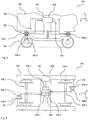
- the vehicle 101 comprises a car body 102 which is supported in the region of its two ends on a chassis in the form of a bogie 103.
- a chassis in the form of a bogie 103.
- the present invention may be used in conjunction with other configurations in which the body is supported on a chassis only.
- a vehicle coordinate system (predetermined by the wheel contact level of the bogie 103) is shown in the figures x, y, z in which the x-coordinate denotes the longitudinal direction of the rail vehicle 101, the y-coordinate the transverse direction of the rail vehicle 101 and the z-coordinate the height direction of the rail vehicle 101.
- the bogie 103 comprises two wheel units in the form of wheelsets 103.1, 103.2, on each of which a bogie frame 103.4 is supported via a primary suspension 103.3.
- the car body 102 is in turn supported by a secondary suspension 103.5 on the bogie frame 103.4.
- the primary suspension 103.3 and the secondary suspension 103.5 are in FIG. 1 simplified as coil springs shown. It is understood, however, that the primary suspension 103.3 or secondary suspension 103.5 can be any suitable spring device.
- the vehicle 101 furthermore comprises a control device 105 with an actuator device 106, by means of which, according to a method according to the invention, an adjustment of the force action between the chassis 103 and the vehicle body 102 is undertaken.
- the actuator device 106 comprises a first actuator unit in the form of a first hydraulic cylinder 106.1 and a second actuator unit in the form of a second hydraulic cylinder 106.2, each of which is articulated at one end to the bogie frame 103.4 and at the other end to the body 102.
- the hydraulic cylinders 106.1, 106.2 are supplied separately with hydraulic energy via a power supply device 106.3 of the actuator device 106 as a function of the control signals of a control unit 107 of the control device 105, as will be explained in more detail below.
- the hydraulic cylinders 106.1, 106.2 are each double-acting hydraulic cylinders which can generate both tensile forces and compressive forces along their longitudinal direction.
- the longitudinal axes of the two hydraulic cylinders 106.1, 106.2 extend in the in the Figures 1 and 2 shown idle state of the vehicle 101 (with nominal load in the straight, level track standing) substantially parallel to the vehicle transverse direction (y-direction), so that via the hydraulic cylinder 106.1, 106.2 between the chassis 103 and the car body 102 each have a force exerted in a plane of action can, which is parallel to the vehicle longitudinal direction (x-direction) and the vehicle transverse direction (y-direction).
- the hydraulic cylinders 106.1, 106.2 are arranged in the vehicle longitudinal direction in each case in the region of one of the ends of the bogie frame 103.4, wherein they substantially point symmetrical to a point on the (vertical to the vehicle height direction) center vertical axis 103.6 of the bogie 103 arranged. This results in particularly favorable kinematic conditions for the force attack.
- the control of the power supply device 106.3 by the control unit 107 and thus the adjustment of the force in the respective hydraulic cylinder 106.1, 106.2 is carried out in dependence on several setting specifications, which serve to implement several adjustment concepts for the force between the chassis 103 and the car body 102.
- a corresponding control law is respectively stored in the control unit 107, according to which in each case an output signal of the control unit 107 is generated and supplied to the energy supply device 106.3 of the actuator unit 106 as an input variable.
- the energy supply device 106.3 then adjusts the adjustment of the force effect as a function of the supplied input variables, superimposing the supplied input variables on each other by a simple summation so as to determine a manipulated variable for the respective hydraulic cylinder 106.1, 106.2, which satisfies all the adjustment concepts.
- the substantially complete elimination of first oscillations of the car body 102 relative to the chassis 103 in the vehicle transverse direction (y direction) in a predetermined first frequency range is tracked as a first adjustment concept.
- the first frequency range extends from 1.0 Hz to 6.0 Hz, that is to say in a region in which such transverse vibrations are usually perceived as particularly disturbing by the passengers of the vehicle 101.
- a first detection quantity E1 which is representative of the lateral acceleration acting on the vehicle body 102 in the vehicle transverse direction (y-direction), is detected in a well-known manner via a first detection device 108 of the control device 105 (comprising one or more acceleration sensors and arranged in the vehicle body 103) is.
- This first detection variable E1 is transmitted to the control unit 107, which filters out the relevant portions of the first detection quantity E1 in the first frequency range via suitable filtering (for example a bandpass filter or the like).
- the control unit 107 uses a first setpoint S1, for a given Lateral acceleration setpoint is representative. Since the lateral acceleration in the present example is ideally to be reduced to the value zero, the lateral acceleration setpoint (over the entire first frequency range) has the value zero.
- a first input variable EA1 for the energy supply unit 106.3 is then determined in the control unit 107 and supplied to the energy supply unit 106.3.
- the substantially complete elimination of a positional deviation of the carbody 102 relative to the chassis 102 in the vehicle transverse direction (y-direction) is tracked in a predetermined second frequency range.
- the second frequency range extends from 0 Hz to 1 Hz.
- a second detection variable E2 is detected in the present example via in the respective hydraulic cylinder 106.1, 106.2 integrated displacement sensors, which is representative of the transverse deflection of the car body 102 from a desired position in the vehicle transverse direction (y-direction).
- This second detection variable E2 is transmitted to the control unit 107, which filters out the relevant portions of the second detection quantity E2 in the second frequency range via suitable filtering (for example a low-pass filter or the like).
- the control unit 107 uses a second setpoint value S2, which is representative of a predetermined transverse deflection setpoint. Since the transverse deflection or position deviation in the vehicle transverse direction is ideally to be reduced to the value zero in the present example, the transverse deflection target value in the present example (over the entire second frequency range) has the value zero.
- a second input variable EA2 for the Energy supply unit 106.3 determined and supplied to the power supply unit 106.3.
- an angular acceleration adjustment concept is pursued in which the substantially complete elimination of angular acceleration of the car body 102 relative to the chassis 103 is rotationally parallel to a vehicle height direction (z-direction) in a predetermined angular acceleration frequency range.
- third frequency range is tracked.
- the angular acceleration frequency range or third frequency range extends from 3.0 Hz to 9.0 Hz in order to prevent unwanted high-frequency torsional vibrations of the chassis 103 with respect to the vehicle body 102, which are particularly disadvantageous for the driving stability of the vehicle 101.
- a third detection variable E3 which is representative of the angular acceleration of the chassis frame 103.4 about the axis of rotation, is detected in a well-known manner via a second detection device 109 of the control device 105 (comprising one or more acceleration sensors and arranged on the bogie frame 103.4).
- This third detection quantity E3 is likewise transmitted to the control unit 107, which filters out the relevant portions of the third detection quantity E3 in the third frequency range via suitable filtering (for example a bandpass filter or the like).
- a third setpoint S3 is used, which is representative of a predetermined angular acceleration target value. Since the angular acceleration in the present example is to be eliminated as much as possible in the present example, the angular acceleration setpoint also has the value zero.
- a third input variable EA3 for the energy supply unit 106.3 is then determined in the control unit 107 and supplied to the energy supply unit 106.3.
- the fourth frequency range extends from 0 Hz to 1.0 Hz, so that the low-frequency, the current curvature of the travel corresponding quasi static Auscardschulen of the chassis 103 with respect to the car body 102 can be actively generated by the actuator 106 at Bogenfahrt.
- a fourth detection quantity E4 is detected, which is representative of the restoring moment of the secondary suspension 103.5.
- the fourth detection variable E4 used is the turn-off angle between the vehicle body 102 and the chassis 103, which is determined from the difference between the signals of the displacement sensors integrated in the respective hydraulic cylinders 106.1, 106.2.
- This fourth detection quantity E4 is subjected to further filtering (for example a low-pass filter or the like) in the control unit 107, in which the relevant portions of this detection quantity E4 are filtered out in the fourth frequency range, which ultimately corresponds to the quasi static angle of turn 103 of the chassis 103 with respect to the car body 102 , From the mechanical conditions of the secondary suspension 103.5, it is then possible to deduce the restoring moment of the secondary suspension 103.5.
- filtering for example a low-pass filter or the like
- a fourth setpoint S4 is used, which is representative of a predetermined Ragstellmomentsollwert. Since in the present example the total restoring torque acting between the vehicle body 102 and the chassis 103 should be eliminated as much as possible (ie the restoring torque resulting from the deflection of the secondary suspension 103.5 should be compensated as far as possible by the force action of the hydraulic cylinders 106.1, 106.2), the restoring torque setpoint likewise has the value zero on.
- a fourth input variable EA4 for the energy supply unit 106.3 is then determined in the control unit 107 and supplied to the energy supply unit 106.3.
- the function of an active transverse suspension is integrated via the first adjustment concept, with which a particularly high level of ride comfort for the passengers is achieved.
- the function of a centering device is integrated, which is in terms of compliance with the airspace profile of advantage.
- the third adjustment concept integrates the function of a roll damper or a rotation inhibitor, which enables stable vehicle travel even at higher speeds (especially in straight track).
- the function of an active steering device of the chassis 103 is integrated via the fourth adjustment concept, which is advantageous in terms of the wear behavior on the wheel and rail.
- FIG. 3 A further advantageous embodiment of the vehicle 201 according to the invention is shown in FIG FIG. 3 shown.
- the vehicle 201 corresponds in its basic design and mode of operation to the vehicle 101 FIGS. 1 and 2 , so that only the differences should be discussed here.
- identical components are provided with the same reference numerals, while similar components are provided with reference numerals increased by 100. Unless otherwise stated below, the features, functions and benefits of this will be determined Components referred to the above statements in connection with the first embodiment.
- the first actuator unit 206.1 and the second actuator unit 206.2 are each formed by a compact unit which has its own (not shown) power supply unit and a first actuator in the form of a first hydraulic cylinder 206.3 and a second actuator in the form of a second hydraulic cylinder 206.4 includes.
- Each of the hydraulic cylinders 206.3, 206.4 is fed via a separate first or second valve unit of the energy supply unit (not shown in greater detail).
- the first valve unit operates in a first operating frequency range, so that the first hydraulic cylinder generates 206.3 forces between the chassis 103 and the car body 102 in the first working frequency range.
- the second valve unit operates in a second operating frequency range, so that the second hydraulic cylinder generates 206.4 forces between the chassis 103 and the car body 102 in the second operating frequency range.
- the second operating frequency range extends from 0 Hz to 2 Hz, while the first operating frequency range extends from 0.5 Hz to 15 Hz. This makes it possible in a simple manner to carry out the above-described settings in the partially different first to fourth frequency ranges with a single compact actuator unit.
- control unit supplies the first to fourth input variables EA1 to EA4 to both actuator units 206.1 and 206.2, which carry out the above-described superimposition according to equation (1), then determine the forces to be set for the moment and magnitude in their hydraulic cylinders 206.3, 206.4 and supply them accordingly with hydraulic energy.
- the determination of the forces to be set in the control unit 107 is carried out and then already corresponding control signals to the respective actuator 206.1 and 206.2 are transmitted.
- FIG. 3 A further advantageous embodiment of the vehicle 301 according to the invention is shown in FIG FIG. 3 represented (whose view those FIG. 2 corresponds).
- the vehicle 301 corresponds in its basic design and operation of the vehicle 101 from FIGS. 1 and 2 , so that only the differences should be discussed here.
- identical components are provided with the identical reference numerals, while similar components are provided with reference numerals increased by the value 200.
- the difference from the execution FIGS. 1 and 2 is in the design of the control device 305.
- the first actuator unit in the form of a first hydraulic cylinder 306.1 and the second actuator unit in the form of a second hydraulic cylinder 306.2 and the central power supply unit 106.3 are combined to form a compact unit which is attached to the car body 102 .
- Each of the hydraulic cylinders 306.1, 306.2 is fed via a separate first or second valve unit of the energy supply unit 106.3 (not shown in greater detail).
- the longitudinal axis and thus the effective direction of the respective hydraulic cylinder 306.1, 306.2 runs substantially parallel to the vehicle longitudinal direction (x-direction).
- the force or displacement of the respective hydraulic cylinder 306.1, 306.2 is transmitted in each case via a simple coupling mechanism 306.5 or 306.6 on the bogie frame 103.4.
- the coupling gear 306.5 or 306.6 each includes a pivotally hinged to the car body 102 angle lever 306.7 or 306.8, via which it is achieved that the transmitted force or displacement in the vehicle transverse direction on the bogie frame 103.4 acts (so that an introduction of force in the bogie frame 103.4 as in the first Embodiment is achieved).
- This design has the advantage that comparatively little space is required in the bogie 103. So only the space for the articulation of the linkage 306.5 or 306.6 must be provided. This is particularly advantageous in view of the very limited availability of installation space in modern bogies.
- the power supply unit 106.3 and the two hydraulic cylinders 306.1, 306.2 can be designed as described in the first embodiment.
- the two hydraulic cylinders 306.1, 306.2 can be made identical.
- the first valve unit can also operate in a first operating frequency range, similar to the second exemplary embodiment, so that the first hydraulic cylinder 306.1 generates forces between the chassis 103 and the vehicle body 102 in the first operating frequency range.
- the second valve unit can then operate in a second operating frequency range, so that the second hydraulic cylinder 306.2 forces between the chassis 103 and the car body 102 in the second.
- the second operating frequency range may range from 0 Hz to 2 Hz, while the first operating frequency range may range from 0.5 Hz to 15 Hz. This makes it possible in a simple manner to carry out the above-described settings in the partially different first to fourth frequency ranges with a single compact actuator unit.
- control unit 107 again supplies the first to fourth input variables EA1 to EA4 to the power supply unit 106.3, which performs the above-described superimposition according to equation (1), then the current time in magnitude and direction in their hydraulic cylinders 306.1, 306.2 Determined forces and supplies them accordingly with hydraulic energy.
Landscapes
- Engineering & Computer Science (AREA)
- Mechanical Engineering (AREA)
- Vehicle Body Suspensions (AREA)
Claims (15)
- Procédé pour ajuster d'un effet de force et/ou une position relative entre un châssis et une caisse de wagon d'un véhicule, notamment un véhicule ferroviaire, dans lequel- un effet de force et/ou une position relative est ajusté entre le châssis (103), en particulier un cadre (103.4) du châssis (103), et la caisse de wagon (102) par un dispositif d'actionnement (106; 206; 306) agissant entre le châssis (103) et la caisse de wagon (102) dans un plan d'action, dans lequel- le plan d'action est défini par une direction longitudinale de véhicule et une direction latérale de véhicule du véhicule,- l'ajustement de l'effet de force et/ou de la position relative est fait en fonction d'une directive d'ajustement pour réaliser un concept d'ajustement prédéterminable pour l'effet de force et/ou la position relative, et- l'ajustement de l'effet de force et/ou la position relative est fait en fonction d'au moins deux directives d'ajustement différentes pour au moins deux concepts d'ajustement différents prédéterminables,
caractérisé en ce que,- comme l'une des au moins deux directives d'ajustement, une directive d'ajustement d'accélération angulaire d'un concept d'ajustement d'accélération angulaire est utilisée, qui concerne la minimisation, en particulier, l'élimination sensiblement complète, d'une accélération angulaire du châssis (103) autour d'un axe de rotation parallèle à la direction de hauteur de véhicule dans une plage de fréquence d'accélération angulaire prédéterminée. - Procédé selon la revendication 1, caractérisé en ce que,- en utilisant chacune des au moins deux directives d'ajustement différentes, une variable d'entrée au dispositif d'actionnement (106; 206) est déterminée et fournie au dispositif d'actionnement (106; 206), et- l'ajustement de l'effet de force et/ou de la position relative est fait en fonction des variables d'entrée fournies, notamment en fonction d'une superposition des variables d'entrée fournies, de préférence en fonction d'une somme des variables d'entrée fournies.
- Procédé selon la revendication 1 ou 2, caractérisé en ce que- une première directive d'ajustement d'un premier concept d'ajustement est utilisé comme l'une des au moins deux directives d'ajustement, dans lequel- le premier concept d'ajustement concerne la minimisation, en particulier, l'élimination sensiblement complète, des vibrations premières de la caisse de wagon (102) par rapport au châssis (103) dans la direction transversale du véhicule dans une première plage de fréquences, dans lequel- la première plage de fréquences, en particulier, étant supérieure à 0,5 Hz à 1,0 Hz, de préférence de 1,0 Hz à 15 Hz, de préférence de 1,0 Hz à 6,0 Hz.
- Procédé selon la revendication 3, caractérisé en ce que- un premier paramètre d'enregistrement est enregistré, qui est représentatif de l'accélération transversale agissant sur la caisse de wagon (102) dans la direction transversale du véhicule,- comme la première directive d'ajustement une première valeur de consigne est utilisée, qui est représentative d'une valeur de consigne d'accélération transversale, et- utilisant le premier paramètre d'enregistrement et la première valeur de consigne, une première grandeur d'entrée pour le dispositif d'actionnement (106; 206; 306) est déterminée et fournie au dispositif d'actionnement (106; 206; 306), dans lequel- la valeur de consigne d'accélération transversale, en particulier, est nul.
- Procédé selon l'une quelconque des revendications précédentes, caractérisé en ce que- une seconde directive d'ajustement d'un second concept d'ajustement est utilisé comme l'une des au moins deux directives d'ajustement dans lequel- le seconde concept d'ajustement concerne la minimisation, en particulier, l'élimination sensiblement complète, d'un un écart de position de la caisse de wagon (102) par rapport au châssis (103) dans la direction transversale du véhicule dans une seconde plage de fréquences, dans lequel- la seconde plage de fréquences, en particulier, est inférieure à und valeur de 0,5 Hz à 2,0 Hz, de préférence de 0 Hz à 1,0 Hz, de préférence de 0 Hz à 0,5 Hz.
- Procédé selon la revendication 5, caractérisé en ce que- un second paramètre d'enregistrement est enregistré, qui est représentatif de la déviation transversale de la caisse de wagon (102) à partir d'une position de consigne dans la direction transversale du véhicule,- comme la seconde directive d'ajustement une seconde valeur de consigne est utilisée, qui est représentative d'une valeur de consigne de déviation transversale et,- utilisant le second paramètre d'enregistrement et la seconde valeur de consigne, une seconde variable d'entrée pour le dispositif d'actionnement (106; 206; 306) est déterminée et fournie au dispositif d'actionnement (106; 206; 306), dans lequel- la valeur de consigne de déviation transversale, en particulier, est nulle.
- Procédé selon l'une quelconque des revendications précédentes, caractérisé en ce que- la plage de fréquence d'accélération angulaire est supérieure à 0,5 Hz à 1,0 Hz, de préférence de 1,0 Hz à 15 Hz, de préférence de 3,0 Hz à 9,0 Hz, se prolonge.
- Procédé selon la revendication 7, caractérisé en ce que- un troisième paramètre d'enregistrement est enregistré, qui est représentatif de l'accélération angulaire du châssis (103) autour de l'axe de rotation,- comme la directive d'ajustement d'accélération angulaire une troisième valeur de consigne est utilisée, qui est représentative d'une valeur de consigne d'accélération angulaire, et- utilisant le troisième paramètre d'enregistrement et la troisième valeur de consigne, une troisième variable d'entrée pour le dispositif d'actionnement (106; 206; 306) est déterminée et fournie au dispositif d'actionnement (106; 206; 306), dans lequel- la valeur de consigne d'accélération angulaire, en particulier, est nulle.
- Procédé selon l'une quelconque des revendications précédentes, caractérisé en ce que- une quatrième directive d'ajustement d'un quatrième concept d'ajustement est utilisé comme l'une des au moins deux directives d'ajustement dans lequel- le premier quatrième concept d'ajustement concerne la minimisation, en particulier, l'élimination sensiblement complète, du moment de rétablissement généré par un dispositif de support (103.5) de la caisse de wagon (102) sur le châssis (103) autour d'un axe de rotation parallèle à une direction de hauteur de véhicule dans une quatrième plage de fréquences,- la quatrième plage de fréquences, en particulier, est inférieure à une valeur de 0,5 Hz à 2,0 Hz, de préférence de 0 Hz à 1,0 Hz, de préférence de 0 Hz à 0,5 Hz.
- Procédé selon la revendication 9, caractérisé en ce que- un quatrième paramètre d'enregistrement est enregistré, qui est représentatif du moment de rétablissement du dispositif de support (103.5)- comme la quatrième directive d'ajustement une quatrième valeur de consigne est utilisée, qui est représentative d'une valeur de consigne de moment de rétablissement, et- utilisant le quatrième paramètre d'enregistrement et la quatrième valeur de consigne, une quatrième variable d'entrée pour le dispositif d'actionnement (106; 206; 306) est déterminée et fournie au dispositif d'actionnement (106; 206),- la valeur de consigne de couple de rétablissement, en particulier, est nul.
- Véhicule, notamment véhicule ferroviaire, avec- une caisse de wagon (102),- un châssis (103), et- un dispositif de commande (105; 205; 305) destiné à exécuter un procédé selon l'une quelconque des revendications précédentes, dans lequel- la caisse de wagon est supporté sur le châssis (103) par l'intermédiaire d'un dispositif de support (103.5),- le dispositif de commande (105; 205; 305) comprend un dispositif d'actionnement (106; 206; 306) connecté avec la caisse de wagon (102) et le châssis (103) et configuré pour ajuster un effet de force et/ou une position relative entre le châssis (103), en particulier un cadre (103.4) du châssis (103), et la caisse de wagon (102) dans un plan d'action, dans lequel- le plan d'action est défini par une direction longitudinale de véhicule et une direction latérale de véhicule du véhicule,- le dispositif de commande (105; 205; 305) est conçu pour ajuster l'effet de force et/ou la position relative en fonction d'au moins deux directives d'ajustement différentes pour au moins deux concepts d'ajustement différents prédéterminables
caractérisé en ce que- le dispositif de commande (105; 205; 305) est conçu pour utiliser, comme l'une des au moins deux directives d'ajustement, une directive d'ajustement d'accélération angulaire d'un concept d'ajustement d'accélération angulaire, qui concerne la minimisation, en particulier, l'élimination sensiblement complète, d'une accélération angulaire du châssis (103) autour d'un axe de rotation parallèle à la direction de hauteur de véhicule dans une plage de fréquence d'accélération angulaire prédéterminée. - Véhicule selon la revendication 11, caractérisé en ce que- le dispositif de commande (105; 205; 305) est conçu pour déterminer, en utilisant chacune des au moins deux directives d'ajustement différentes, une variable d'entrée au dispositif d'actionnement (106; 206) et pour fournir la dernière au dispositif d'actionnement (106; 206), et- le dispositif d'actionnement (106; 206) est conçu pour l'ajustement de l'effet de force et/ou de la position relative est fait en fonction des variables d'entrée fournies, notamment en fonction d'une superposition des variables d'entrée fournies, de préférence en fonction d'une somme des variables d'entrée fournies.
- Véhicule selon la revendication 11 ou 12, caractérisé en ce que- le dispositif de commande (105; 205; 305) comprend un premier dispositif d'enregistrement (108) pour enregistrer un premier paramètre d'enregistrement, qui est représentatif de l'accélération transversale agissant sur la caisse de wagon (102) dans la direction transversale du véhicule, le dispositif de commande (105; 205; 305) utilise comme la première directive d'ajustement une première valeur de consigne est utilisée, qui est représentative d'une valeur de consigne d'accélération transversale, et le dispositif de commande (105; 205; 305) en utilisant le premier paramètre d'enregistrement et la première valeur de consigne, détermine une première grandeur d'entrée pour le dispositif d'actionnement (106; 206; 306) et fournit la dernière au dispositif d'actionnement (106; 206; 306), dans lequel la valeur de consigne d'accélération transversale, en particulier, est nul,
et/ou- le dispositif de commande (105; 205; 305) comprend un second dispositif d'enregistrement pour enregistrer un second paramètre d'enregistrement, qui est représentatif de la déviation transversale de la caisse de wagon (102) à partir d'une position de consigne dans la direction transversale du véhicule, le dispositif de commande (105; 205; 305) utilise comme la seconde directive d'ajustement une seconde valeur de consigne est utilisée, qui est représentative d'une valeur de consigne de déviation transversale et, le dispositif de commande (105; 205; 305), en utilisant le second paramètre d'enregistrement et la seconde valeur de consigne, détermine une seconde variable d'entrée pour le dispositif d'actionnement (106; 206; 306) et fournit la dernière au dispositif d'actionnement (106; 206; 306), dans lequel la valeur de consigne de déviation transversale, en particulier, est nulle.
et/ou- le dispositif de commande (105; 205; 305) comprend un troisième dispositif d'enregistrement pour enregistrer un troisième paramètre d'enregistrement dans une troisième plage de fréquence, qui est représentatif de l'accélération angulaire du châssis (103) autour de l'axe de rotation, et le dispositif de commande (105; 205; 305), en utilisant le troisième paramètre d'enregistrement et la troisième valeur de consigne, détermine une troisième variable d'entrée pour le dispositif d'actionnement (106; 206; 306) et fournit la dernière au dispositif d'actionnement (106; 206; 306), dans lequel la valeur de consigne d'accélération angulaire, en particulier, est nulle.
et/ou- le dispositif de commande (105; 205; 305) comprend un troisième dispositif d'enregistrement pour enregistrer un quatrième paramètre d'enregistrement, qui est représentatif du moment de rétablissement du dispositif de support (103.5), le dispositif de commande (105; 205; 305) utilise comme la quatrième directive d'ajustement une quatrième valeur de consigne est utilisée, qui est représentative d'une valeur de consigne de moment de rétablissement, et le dispositif de commande (105; 205; 305), en utilisant le quatrième paramètre d'enregistrement et la quatrième valeur de consigne, détermine une quatrième variable d'entrée pour le dispositif d'actionnement (106; 206; 306) et fournit la dernière au dispositif d'actionnement (106; 206), la valeur de consigne de couple de rétablissement, en particulier, est nul. - Véhicule selon l'une des revendications 11 à 13, caractérisé en ce que- le dispositif d'actionnement (106; 206; 306) comprend au moins deux unités d'actionnement (106,1, 106,2, 206,1, 206,2, 306,1, 306,2) agissant dans la direction transversale du véhicule entre la caisse de wagon (102) et le châssis (103), dans lequel- les deux unités d'actionnement (106.1, 106.2; 206.1, 206.2), dans la direction longitudinale du véhicule, en particulier, sont disposées des deux côtés d'un centre de châssis, en particulier, sensiblement symétriquement par rapport au centre du châssis, de préférence, sont disposés dans la région d'une extrémité avant et une extrémité arrière du châssis (103),
et/ou- au moins une des unités d'actionnement (106.1, 106.2; 206.1, 206.2), en particulier, comprend un actionneur linéaire, en particulier, un vérin hydraulique, au moins un principalement orienté dans le sens transversal du véhicule,. - Véhicule selon l'une des revendications 11 à 14, caractérisé en ce que- le dispositif d'actionnement (206; 306) comprend au moins une unité d'actionnement (206.1; 306.1, 306.2) comportant un premier actionneur (206.3) et un second actionneur (206.4), dans lequel- le premier actionneur (206.3) est adapté pour générer des forces et/ou des mouvements de réglage entre le châssis (103) et la caisse de wagon (102) dans une première plage de fréquences d'opération,- le seconde actionneur (206.4) est adapté pour générer des forces et/ou des mouvements de réglage entre le châssis (103) et la caisse de wagon (102) dans une seconde plage de fréquences d'opération,- la première gamme de fréquences d'opération, en particulier, étant au moins partiellement, notamment entièrement, au-dessus de la seconde plage de fréquences d'opération
et/ou- la seconde plage de fréquences d'opération , en particulier, étant de 0 Hz à 2 Hz, de préférence de 0,5 Hz à 1,0 Hz, ,- et/ou- la première gamme de fréquences d'opération , en particulier, étant de 0,5 Hz à 15 Hz, de préférence de 3,0 Hz à 9,0 Hz.
Applications Claiming Priority (1)
| Application Number | Priority Date | Filing Date | Title |
|---|---|---|---|
| DE201010008540 DE102010008540A1 (de) | 2010-02-18 | 2010-02-18 | Aktive Kopplung zwischen Fahrwerk und Wagenkasten bei einem Fahrzeug |
Publications (2)
| Publication Number | Publication Date |
|---|---|
| EP2361815A1 EP2361815A1 (fr) | 2011-08-31 |
| EP2361815B1 true EP2361815B1 (fr) | 2017-04-05 |
Family
ID=44170087
Family Applications (1)
| Application Number | Title | Priority Date | Filing Date |
|---|---|---|---|
| EP11154699.0A Active EP2361815B1 (fr) | 2010-02-18 | 2011-02-16 | Couplage actif entre un train d'atterrissage et une caisse dans un véhicule |
Country Status (2)
| Country | Link |
|---|---|
| EP (1) | EP2361815B1 (fr) |
| DE (1) | DE102010008540A1 (fr) |
Families Citing this family (2)
| Publication number | Priority date | Publication date | Assignee | Title |
|---|---|---|---|---|
| DE102018009962B3 (de) * | 2018-12-20 | 2020-04-23 | Aventics Gmbh | Ventilanordnung und Verfahren zur Regelung des Luftfederungsniveaus eines Schienenfahrzeugs |
| DE102024200454A1 (de) * | 2024-01-18 | 2025-07-24 | Siemens Mobility GmbH | Querführungsanordnung |
Family Cites Families (2)
| Publication number | Priority date | Publication date | Assignee | Title |
|---|---|---|---|---|
| IT1216147B (it) * | 1988-03-18 | 1990-02-22 | Socimi | Dispositivo per il controllo delle sollecitazioni dinamiche trasmesse dalla superficie di rotolamento alla cassa di un veicolo, in particolare un veicolo ferrotramviario. |
| DE4426166A1 (de) * | 1994-07-23 | 1996-04-18 | Haberstock Ferdinand Dr Ing | Verfahren zur Querstabilisierung von Schienenfahrzeugen mit gleisbogenabhängiger Wagenkastensteuerung |
-
2010
- 2010-02-18 DE DE201010008540 patent/DE102010008540A1/de not_active Ceased
-
2011
- 2011-02-16 EP EP11154699.0A patent/EP2361815B1/fr active Active
Non-Patent Citations (1)
| Title |
|---|
| None * |
Also Published As
| Publication number | Publication date |
|---|---|
| EP2361815A1 (fr) | 2011-08-31 |
| DE102010008540A1 (de) | 2011-08-18 |
Similar Documents
| Publication | Publication Date | Title |
|---|---|---|
| EP2414208B1 (fr) | Véhicule à compensation du roulis | |
| EP0894053B1 (fr) | Systeme actif de suspension | |
| EP2021223A2 (fr) | Procédé de réglage d'un mécanisme de roulement de véhicule ferroviaire | |
| EP0655378B1 (fr) | Dispositif et procédé pour orienter les essieux des véhicules ferroviaires | |
| EP2483125B1 (fr) | Système amortisseur pour la régulation de niveau dans un véhicule | |
| DE102008053008A1 (de) | Verfahren und System zur Beeinflussung der Bewegung eines in seinen Bewegungsabläufen steuerbaren oder regelbaren Fahrzeugaufbaus eines Kraftfahrzeuges und Fahrzeug | |
| EP2287024B1 (fr) | Dispositif de réglage du parallélisme | |
| DE102016001592A1 (de) | Verfahren zur Beeinflussung der Fahrtrichtung von Kraftfahrzeugen | |
| WO2015055363A1 (fr) | Dispositif d'angle de braquage pour un véhicule automobile | |
| EP1451030B1 (fr) | Reglage de position d'un corps de voiture d'un vehicule | |
| DE102008017950A1 (de) | Verfahren zum Beeinflussen der Querdynamik eines Fahrzeugs | |
| WO2010113045A2 (fr) | Véhicule à compensation du roulis | |
| DE102010021561A1 (de) | Verfahren zur Fahrzeuglenkung mit einer Fahrzeuglenkvorrichtung | |
| DE102008012007B4 (de) | Verfahren zum Reduzieren einer Kipptendenz eines Kraftwagens und ein Lenksystem | |
| EP1542877A1 (fr) | Procede pour la regulation ou la commande d'un chassis actif ou controlable | |
| DE102017212546B4 (de) | Achsenbaugruppe | |
| EP2361815B1 (fr) | Couplage actif entre un train d'atterrissage et une caisse dans un véhicule | |
| DE68911532T2 (de) | Kraftanlenkungsvorrichtung zur neigung oder querstabilisierung eines fahrzeugoberbaus. | |
| EP3932777B1 (fr) | Fonction de rappel de fin de course pour une direction de véhicule | |
| WO2004089663A1 (fr) | Amortissement actif de roulis | |
| WO2008090024A1 (fr) | Véhicule à éléments multiples | |
| DE102019216934A1 (de) | Verfahren zum Betrieb eines Fahrzeugs und Fahrzeug | |
| DE102019201942A1 (de) | Verfahren zum Betreiben eines Fahrzeugs | |
| DE202006015828U1 (de) | Knickgelenktes Fahrzeug, insbesondere Radlader | |
| EP2159125A1 (fr) | Dispositif de freinage rotatif pour un véhicule |
Legal Events
| Date | Code | Title | Description |
|---|---|---|---|
| PUAI | Public reference made under article 153(3) epc to a published international application that has entered the european phase |
Free format text: ORIGINAL CODE: 0009012 |
|
| AK | Designated contracting states |
Kind code of ref document: A1 Designated state(s): AL AT BE BG CH CY CZ DE DK EE ES FI FR GB GR HR HU IE IS IT LI LT LU LV MC MK MT NL NO PL PT RO RS SE SI SK SM TR |
|
| AX | Request for extension of the european patent |
Extension state: BA ME |
|
| 17P | Request for examination filed |
Effective date: 20120229 |
|
| 17Q | First examination report despatched |
Effective date: 20141210 |
|
| GRAP | Despatch of communication of intention to grant a patent |
Free format text: ORIGINAL CODE: EPIDOSNIGR1 |
|
| INTG | Intention to grant announced |
Effective date: 20161012 |
|
| GRAS | Grant fee paid |
Free format text: ORIGINAL CODE: EPIDOSNIGR3 |
|
| GRAA | (expected) grant |
Free format text: ORIGINAL CODE: 0009210 |
|
| AK | Designated contracting states |
Kind code of ref document: B1 Designated state(s): AL AT BE BG CH CY CZ DE DK EE ES FI FR GB GR HR HU IE IS IT LI LT LU LV MC MK MT NL NO PL PT RO RS SE SI SK SM TR |
|
| REG | Reference to a national code |
Ref country code: GB Ref legal event code: FG4D Free format text: NOT ENGLISH |
|
| REG | Reference to a national code |
Ref country code: CH Ref legal event code: EP |
|
| REG | Reference to a national code |
Ref country code: AT Ref legal event code: REF Ref document number: 881510 Country of ref document: AT Kind code of ref document: T Effective date: 20170415 |
|
| REG | Reference to a national code |
Ref country code: IE Ref legal event code: FG4D Free format text: LANGUAGE OF EP DOCUMENT: GERMAN |
|
| REG | Reference to a national code |
Ref country code: DE Ref legal event code: R096 Ref document number: 502011011961 Country of ref document: DE |
|
| REG | Reference to a national code |
Ref country code: CH Ref legal event code: NV Representative=s name: SCHMAUDER AND PARTNER AG PATENT- UND MARKENANW, CH |
|
| REG | Reference to a national code |
Ref country code: SE Ref legal event code: TRGR |
|
| REG | Reference to a national code |
Ref country code: NL Ref legal event code: MP Effective date: 20170405 |
|
| REG | Reference to a national code |
Ref country code: LT Ref legal event code: MG4D |
|
| PG25 | Lapsed in a contracting state [announced via postgrant information from national office to epo] |
Ref country code: NL Free format text: LAPSE BECAUSE OF FAILURE TO SUBMIT A TRANSLATION OF THE DESCRIPTION OR TO PAY THE FEE WITHIN THE PRESCRIBED TIME-LIMIT Effective date: 20170405 |
|
| PG25 | Lapsed in a contracting state [announced via postgrant information from national office to epo] |
Ref country code: HR Free format text: LAPSE BECAUSE OF FAILURE TO SUBMIT A TRANSLATION OF THE DESCRIPTION OR TO PAY THE FEE WITHIN THE PRESCRIBED TIME-LIMIT Effective date: 20170405 Ref country code: ES Free format text: LAPSE BECAUSE OF FAILURE TO SUBMIT A TRANSLATION OF THE DESCRIPTION OR TO PAY THE FEE WITHIN THE PRESCRIBED TIME-LIMIT Effective date: 20170405 Ref country code: GR Free format text: LAPSE BECAUSE OF FAILURE TO SUBMIT A TRANSLATION OF THE DESCRIPTION OR TO PAY THE FEE WITHIN THE PRESCRIBED TIME-LIMIT Effective date: 20170706 Ref country code: LT Free format text: LAPSE BECAUSE OF FAILURE TO SUBMIT A TRANSLATION OF THE DESCRIPTION OR TO PAY THE FEE WITHIN THE PRESCRIBED TIME-LIMIT Effective date: 20170405 Ref country code: FI Free format text: LAPSE BECAUSE OF FAILURE TO SUBMIT A TRANSLATION OF THE DESCRIPTION OR TO PAY THE FEE WITHIN THE PRESCRIBED TIME-LIMIT Effective date: 20170405 Ref country code: NO Free format text: LAPSE BECAUSE OF FAILURE TO SUBMIT A TRANSLATION OF THE DESCRIPTION OR TO PAY THE FEE WITHIN THE PRESCRIBED TIME-LIMIT Effective date: 20170705 |
|
| PG25 | Lapsed in a contracting state [announced via postgrant information from national office to epo] |
Ref country code: BG Free format text: LAPSE BECAUSE OF FAILURE TO SUBMIT A TRANSLATION OF THE DESCRIPTION OR TO PAY THE FEE WITHIN THE PRESCRIBED TIME-LIMIT Effective date: 20170705 Ref country code: LV Free format text: LAPSE BECAUSE OF FAILURE TO SUBMIT A TRANSLATION OF THE DESCRIPTION OR TO PAY THE FEE WITHIN THE PRESCRIBED TIME-LIMIT Effective date: 20170405 Ref country code: PL Free format text: LAPSE BECAUSE OF FAILURE TO SUBMIT A TRANSLATION OF THE DESCRIPTION OR TO PAY THE FEE WITHIN THE PRESCRIBED TIME-LIMIT Effective date: 20170405 Ref country code: IS Free format text: LAPSE BECAUSE OF FAILURE TO SUBMIT A TRANSLATION OF THE DESCRIPTION OR TO PAY THE FEE WITHIN THE PRESCRIBED TIME-LIMIT Effective date: 20170805 Ref country code: RS Free format text: LAPSE BECAUSE OF FAILURE TO SUBMIT A TRANSLATION OF THE DESCRIPTION OR TO PAY THE FEE WITHIN THE PRESCRIBED TIME-LIMIT Effective date: 20170405 |
|
| REG | Reference to a national code |
Ref country code: DE Ref legal event code: R097 Ref document number: 502011011961 Country of ref document: DE |
|
| PG25 | Lapsed in a contracting state [announced via postgrant information from national office to epo] |
Ref country code: SK Free format text: LAPSE BECAUSE OF FAILURE TO SUBMIT A TRANSLATION OF THE DESCRIPTION OR TO PAY THE FEE WITHIN THE PRESCRIBED TIME-LIMIT Effective date: 20170405 Ref country code: CZ Free format text: LAPSE BECAUSE OF FAILURE TO SUBMIT A TRANSLATION OF THE DESCRIPTION OR TO PAY THE FEE WITHIN THE PRESCRIBED TIME-LIMIT Effective date: 20170405 Ref country code: RO Free format text: LAPSE BECAUSE OF FAILURE TO SUBMIT A TRANSLATION OF THE DESCRIPTION OR TO PAY THE FEE WITHIN THE PRESCRIBED TIME-LIMIT Effective date: 20170405 Ref country code: DK Free format text: LAPSE BECAUSE OF FAILURE TO SUBMIT A TRANSLATION OF THE DESCRIPTION OR TO PAY THE FEE WITHIN THE PRESCRIBED TIME-LIMIT Effective date: 20170405 Ref country code: EE Free format text: LAPSE BECAUSE OF FAILURE TO SUBMIT A TRANSLATION OF THE DESCRIPTION OR TO PAY THE FEE WITHIN THE PRESCRIBED TIME-LIMIT Effective date: 20170405 |
|
| PLBE | No opposition filed within time limit |
Free format text: ORIGINAL CODE: 0009261 |
|
| STAA | Information on the status of an ep patent application or granted ep patent |
Free format text: STATUS: NO OPPOSITION FILED WITHIN TIME LIMIT |
|
| PG25 | Lapsed in a contracting state [announced via postgrant information from national office to epo] |
Ref country code: SM Free format text: LAPSE BECAUSE OF FAILURE TO SUBMIT A TRANSLATION OF THE DESCRIPTION OR TO PAY THE FEE WITHIN THE PRESCRIBED TIME-LIMIT Effective date: 20170405 Ref country code: IT Free format text: LAPSE BECAUSE OF FAILURE TO SUBMIT A TRANSLATION OF THE DESCRIPTION OR TO PAY THE FEE WITHIN THE PRESCRIBED TIME-LIMIT Effective date: 20170405 |
|
| 26N | No opposition filed |
Effective date: 20180108 |
|
| PG25 | Lapsed in a contracting state [announced via postgrant information from national office to epo] |
Ref country code: SI Free format text: LAPSE BECAUSE OF FAILURE TO SUBMIT A TRANSLATION OF THE DESCRIPTION OR TO PAY THE FEE WITHIN THE PRESCRIBED TIME-LIMIT Effective date: 20170405 |
|
| PG25 | Lapsed in a contracting state [announced via postgrant information from national office to epo] |
Ref country code: MC Free format text: LAPSE BECAUSE OF FAILURE TO SUBMIT A TRANSLATION OF THE DESCRIPTION OR TO PAY THE FEE WITHIN THE PRESCRIBED TIME-LIMIT Effective date: 20170405 Ref country code: MT Free format text: LAPSE BECAUSE OF FAILURE TO SUBMIT A TRANSLATION OF THE DESCRIPTION OR TO PAY THE FEE WITHIN THE PRESCRIBED TIME-LIMIT Effective date: 20170405 |
|
| REG | Reference to a national code |
Ref country code: IE Ref legal event code: MM4A |
|
| REG | Reference to a national code |
Ref country code: BE Ref legal event code: MM Effective date: 20180228 |
|
| PG25 | Lapsed in a contracting state [announced via postgrant information from national office to epo] |
Ref country code: LU Free format text: LAPSE BECAUSE OF NON-PAYMENT OF DUE FEES Effective date: 20180216 |
|
| REG | Reference to a national code |
Ref country code: FR Ref legal event code: ST Effective date: 20181031 |
|
| PG25 | Lapsed in a contracting state [announced via postgrant information from national office to epo] |
Ref country code: IE Free format text: LAPSE BECAUSE OF NON-PAYMENT OF DUE FEES Effective date: 20180216 |
|
| PG25 | Lapsed in a contracting state [announced via postgrant information from national office to epo] |
Ref country code: FR Free format text: LAPSE BECAUSE OF NON-PAYMENT OF DUE FEES Effective date: 20180228 Ref country code: BE Free format text: LAPSE BECAUSE OF NON-PAYMENT OF DUE FEES Effective date: 20180228 |
|
| PG25 | Lapsed in a contracting state [announced via postgrant information from national office to epo] |
Ref country code: TR Free format text: LAPSE BECAUSE OF FAILURE TO SUBMIT A TRANSLATION OF THE DESCRIPTION OR TO PAY THE FEE WITHIN THE PRESCRIBED TIME-LIMIT Effective date: 20170405 |
|
| PG25 | Lapsed in a contracting state [announced via postgrant information from national office to epo] |
Ref country code: PT Free format text: LAPSE BECAUSE OF FAILURE TO SUBMIT A TRANSLATION OF THE DESCRIPTION OR TO PAY THE FEE WITHIN THE PRESCRIBED TIME-LIMIT Effective date: 20170405 Ref country code: HU Free format text: LAPSE BECAUSE OF FAILURE TO SUBMIT A TRANSLATION OF THE DESCRIPTION OR TO PAY THE FEE WITHIN THE PRESCRIBED TIME-LIMIT; INVALID AB INITIO Effective date: 20110216 |
|
| PG25 | Lapsed in a contracting state [announced via postgrant information from national office to epo] |
Ref country code: MK Free format text: LAPSE BECAUSE OF NON-PAYMENT OF DUE FEES Effective date: 20170405 Ref country code: CY Free format text: LAPSE BECAUSE OF FAILURE TO SUBMIT A TRANSLATION OF THE DESCRIPTION OR TO PAY THE FEE WITHIN THE PRESCRIBED TIME-LIMIT Effective date: 20170405 |
|
| PG25 | Lapsed in a contracting state [announced via postgrant information from national office to epo] |
Ref country code: AL Free format text: LAPSE BECAUSE OF FAILURE TO SUBMIT A TRANSLATION OF THE DESCRIPTION OR TO PAY THE FEE WITHIN THE PRESCRIBED TIME-LIMIT Effective date: 20170405 |
|
| P01 | Opt-out of the competence of the unified patent court (upc) registered |
Effective date: 20230822 |
|
| PGFP | Annual fee paid to national office [announced via postgrant information from national office to epo] |
Ref country code: DE Payment date: 20250218 Year of fee payment: 15 |
|
| PGFP | Annual fee paid to national office [announced via postgrant information from national office to epo] |
Ref country code: SE Payment date: 20250218 Year of fee payment: 15 |
|
| PGFP | Annual fee paid to national office [announced via postgrant information from national office to epo] |
Ref country code: AT Payment date: 20250219 Year of fee payment: 15 Ref country code: CH Payment date: 20250301 Year of fee payment: 15 |
|
| PGFP | Annual fee paid to national office [announced via postgrant information from national office to epo] |
Ref country code: GB Payment date: 20250219 Year of fee payment: 15 |