EP2361829A2 - Elektrischer Steckverbinder - Google Patents
Elektrischer Steckverbinder Download PDFInfo
- Publication number
- EP2361829A2 EP2361829A2 EP11153924A EP11153924A EP2361829A2 EP 2361829 A2 EP2361829 A2 EP 2361829A2 EP 11153924 A EP11153924 A EP 11153924A EP 11153924 A EP11153924 A EP 11153924A EP 2361829 A2 EP2361829 A2 EP 2361829A2
- Authority
- EP
- European Patent Office
- Prior art keywords
- electrical connector
- aircraft
- fuselage
- bulkhead
- connection terminal
- Prior art date
- Legal status (The legal status is an assumption and is not a legal conclusion. Google has not performed a legal analysis and makes no representation as to the accuracy of the status listed.)
- Withdrawn
Links
- 238000000034 method Methods 0.000 claims description 2
- 230000015572 biosynthetic process Effects 0.000 claims 2
- 239000002184 metal Substances 0.000 description 1
- 238000007789 sealing Methods 0.000 description 1
- 239000003566 sealing material Substances 0.000 description 1
Images

Classifications
-
- H—ELECTRICITY
- H01—ELECTRIC ELEMENTS
- H01R—ELECTRICALLY-CONDUCTIVE CONNECTIONS; STRUCTURAL ASSOCIATIONS OF A PLURALITY OF MUTUALLY-INSULATED ELECTRICAL CONNECTING ELEMENTS; COUPLING DEVICES; CURRENT COLLECTORS
- H01R43/00—Apparatus or processes specially adapted for manufacturing, assembling, maintaining, or repairing of line connectors or current collectors or for joining electric conductors
- H01R43/18—Apparatus or processes specially adapted for manufacturing, assembling, maintaining, or repairing of line connectors or current collectors or for joining electric conductors for manufacturing bases or cases for contact members
-
- B—PERFORMING OPERATIONS; TRANSPORTING
- B64—AIRCRAFT; AVIATION; COSMONAUTICS
- B64C—AEROPLANES; HELICOPTERS
- B64C1/00—Fuselages; Constructional features common to fuselages, wings, stabilising surfaces or the like
- B64C1/06—Frames; Stringers; Longerons ; Fuselage sections
- B64C1/10—Bulkheads
-
- H—ELECTRICITY
- H01—ELECTRIC ELEMENTS
- H01R—ELECTRICALLY-CONDUCTIVE CONNECTIONS; STRUCTURAL ASSOCIATIONS OF A PLURALITY OF MUTUALLY-INSULATED ELECTRICAL CONNECTING ELEMENTS; COUPLING DEVICES; CURRENT COLLECTORS
- H01R13/00—Details of coupling devices of the kinds covered by groups H01R12/70 or H01R24/00 - H01R33/00
- H01R13/46—Bases; Cases
- H01R13/514—Bases; Cases composed as a modular blocks or assembly, i.e. composed of co-operating parts provided with contact members or holding contact members between them
-
- H—ELECTRICITY
- H01—ELECTRIC ELEMENTS
- H01R—ELECTRICALLY-CONDUCTIVE CONNECTIONS; STRUCTURAL ASSOCIATIONS OF A PLURALITY OF MUTUALLY-INSULATED ELECTRICAL CONNECTING ELEMENTS; COUPLING DEVICES; CURRENT COLLECTORS
- H01R13/00—Details of coupling devices of the kinds covered by groups H01R12/70 or H01R24/00 - H01R33/00
- H01R13/46—Bases; Cases
- H01R13/52—Dustproof, splashproof, drip-proof, waterproof, or flameproof cases
- H01R13/521—Sealing between contact members and housing, e.g. sealing insert
-
- H—ELECTRICITY
- H01—ELECTRIC ELEMENTS
- H01R—ELECTRICALLY-CONDUCTIVE CONNECTIONS; STRUCTURAL ASSOCIATIONS OF A PLURALITY OF MUTUALLY-INSULATED ELECTRICAL CONNECTING ELEMENTS; COUPLING DEVICES; CURRENT COLLECTORS
- H01R13/00—Details of coupling devices of the kinds covered by groups H01R12/70 or H01R24/00 - H01R33/00
- H01R13/46—Bases; Cases
- H01R13/533—Bases, cases made for use in extreme conditions, e.g. high temperature, radiation, vibration, corrosive environment, pressure
-
- H—ELECTRICITY
- H01—ELECTRIC ELEMENTS
- H01R—ELECTRICALLY-CONDUCTIVE CONNECTIONS; STRUCTURAL ASSOCIATIONS OF A PLURALITY OF MUTUALLY-INSULATED ELECTRICAL CONNECTING ELEMENTS; COUPLING DEVICES; CURRENT COLLECTORS
- H01R13/00—Details of coupling devices of the kinds covered by groups H01R12/70 or H01R24/00 - H01R33/00
- H01R13/73—Means for mounting coupling parts to apparatus or structures, e.g. to a wall
- H01R13/74—Means for mounting coupling parts in openings of a panel
-
- Y—GENERAL TAGGING OF NEW TECHNOLOGICAL DEVELOPMENTS; GENERAL TAGGING OF CROSS-SECTIONAL TECHNOLOGIES SPANNING OVER SEVERAL SECTIONS OF THE IPC; TECHNICAL SUBJECTS COVERED BY FORMER USPC CROSS-REFERENCE ART COLLECTIONS [XRACs] AND DIGESTS
- Y10—TECHNICAL SUBJECTS COVERED BY FORMER USPC
- Y10T—TECHNICAL SUBJECTS COVERED BY FORMER US CLASSIFICATION
- Y10T29/00—Metal working
- Y10T29/49—Method of mechanical manufacture
- Y10T29/49002—Electrical device making
- Y10T29/49117—Conductor or circuit manufacturing
- Y10T29/49174—Assembling terminal to elongated conductor
Definitions
- the present invention concerns an electrical connector. More specifically, the present invention concerns an aircraft pressure bulkhead electrical connector.
- Aircraft fuselages are pressurised to allow the occupants to travel in comfort and safety.
- the aircraft wings are generally not pressurised, and the interior space of the wing adopts the ambient pressure, which at altitude is significantly less than the pressure inside the fuselage.
- such cables are routed through the boundary between the fuselage and the wing interior (the fuselage wall). This is achieved by passing the cables through a rubber pressure bung which fits into a bore in the fuselage wall. The pressure bung grips the cable and is gripped within the bore such that a pressure differential between the wing interior and the fuselage is maintained. Once the cables have passed into the fuselage, they are routed to a terminal block.
- a problem with such systems is that aircraft wings are often supplied as subassemblies.
- the various cables must protrude from the fuselage side of the wing by a distance sufficient to route them through the pressure bungs and to the terminal block within the aircraft fuselage.
- the various cables are therefore exposed until the wing is attached to the fuselage. This means that they are exposed to external forces and elements and may be damaged before the wing can be assembled to the fuselage.
- the various protruding cables are temporarily attached to a wing outer surface (e.g. the upper surface).
- a wing outer surface e.g. the upper surface.
- the protruding cables also require a great deal of manipulation to feed them through the fuselage wall via the pressure bungs which is time consuming and potentially damaging to the cables.
- an aircraft fuselage comprising a pressure bulkhead according to the second aspect wherein the first connection terminal faces outwardly from the fuselage at a position configured to interface with an aircraft wing.
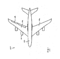
- Figure 1 is a plan view of an aircraft
- Figure 2 is a plan section view of an aircraft pressure bulkhead electrical connector in accordance with the present invention.
- a passenger aircraft 100 comprises a fuselage 102, a first wing 104 and a second wing 106.
- the fuselage 102 When at altitude, the fuselage 102 is pressurised to an air pressure level that is comfortable for the occupants within. This pressure is significantly higher than the ambient pressure at a typical passenger aircraft cruising altitude.
- a pressure bulkhead 112 is shown which is formed from part of the fuselage wall.
- the pressure bulkhead 112 delimits an interior space 114 of the fuselage 110 and a wing space 116 within the wing 104.
- the interior space 114 is pressurised whereas the wing space 116 is at ambient pressure. Therefore during flight there is a pressure differential across the bulkhead 112.
- a plurality of connector interface modules 124 are sealed within the connector body 122.
- Each connector interface 124 has a first connection terminal 126 and a second connector terminal 128 comprising a number of electrical contacts (not visible). The corresponding electrical contacts of each terminal 126, 128 are in electrical connection across the connector interface 124.
- the connector interface modules 124 are arranged such that the first terminal 126 projects on the interior space 114 and the second terminal projects towards the wing space 116.
- wing assembly is made much simpler, as long cables are not required to be passed through rubber sealing bungs in the bulkhead.
- the interior side of the connector may not comprise terminals, but may be directly connected to cables routed inside the fuselage.
- the system may be modular in nature.
- the electrical connector may comprise a carrier or frame sealed to the aircraft fuselage which defines a plurality of bores to receive various types of different connection terminals.
- the individual connection terminals are sealed to the frame or carrier.
- Each individual connection terminal may be constructed from two parts attachable from each side of the carrier to grip and seal against the carrier in use.
- the individual connection terminals may be removable such that they can be replaced.
Landscapes
- Engineering & Computer Science (AREA)
- Mechanical Engineering (AREA)
- Aviation & Aerospace Engineering (AREA)
- Manufacturing & Machinery (AREA)
- Connector Housings Or Holding Contact Members (AREA)
Applications Claiming Priority (1)
| Application Number | Priority Date | Filing Date | Title |
|---|---|---|---|
| GBGB1002996.5A GB201002996D0 (en) | 2010-02-23 | 2010-02-23 | Electrical connector |
Publications (2)
| Publication Number | Publication Date |
|---|---|
| EP2361829A2 true EP2361829A2 (de) | 2011-08-31 |
| EP2361829A3 EP2361829A3 (de) | 2014-01-15 |
Family
ID=42114203
Family Applications (1)
| Application Number | Title | Priority Date | Filing Date |
|---|---|---|---|
| EP11153924.3A Withdrawn EP2361829A3 (de) | 2010-02-23 | 2011-02-09 | Elektrischer Steckverbinder |
Country Status (3)
| Country | Link |
|---|---|
| US (2) | US8702448B2 (de) |
| EP (1) | EP2361829A3 (de) |
| GB (1) | GB201002996D0 (de) |
Cited By (2)
| Publication number | Priority date | Publication date | Assignee | Title |
|---|---|---|---|---|
| FR3005936A1 (fr) * | 2013-05-24 | 2014-11-28 | Airbus Operations Sas | Plaque de support pour le passage de systemes entre deux zones a pressurisations differentes d'un aeronef. |
| FR3039807A1 (fr) * | 2015-08-04 | 2017-02-10 | Airbus Operations Sas | Dispositif d’interface pour la connexion et le passage d’une route electrique a travers une paroi etanche d’un aeronef. |
Families Citing this family (2)
| Publication number | Priority date | Publication date | Assignee | Title |
|---|---|---|---|---|
| DE102017126469B4 (de) * | 2017-11-10 | 2020-03-12 | Airbus Operations Gmbh | Verbindungsmodul und System zum Durchführen von Leitungen durch ein Druckschott |
| US10516232B2 (en) * | 2018-05-21 | 2019-12-24 | The Boeing Company | Electrical multi-connector feedthrough panel and method therefor |
Citations (1)
| Publication number | Priority date | Publication date | Assignee | Title |
|---|---|---|---|---|
| US5197903A (en) * | 1992-03-02 | 1993-03-30 | Amp Incorporated | Firewall connector |
Family Cites Families (10)
| Publication number | Priority date | Publication date | Assignee | Title |
|---|---|---|---|---|
| US2656203A (en) * | 1948-10-14 | 1953-10-20 | Musser Clarence Walton | Cable and housing connector |
| US4591114A (en) * | 1985-02-07 | 1986-05-27 | Alvin Block | Automatic interlock connector arrangement for radio-controlled model airplanes |
| US4684190A (en) * | 1986-03-05 | 1987-08-04 | General Motors Corporation | Sealed electrical connector with shroud |
| US5009374A (en) * | 1988-04-26 | 1991-04-23 | Carl Manfredi | Aircraft with releasable wings |
| US4909760A (en) * | 1989-03-27 | 1990-03-20 | General Motors Corporation | Electrical connector having combination cable and bolt seal |
| US4921437A (en) * | 1989-03-29 | 1990-05-01 | Amp Incorporated | Sealed electrical connector assembly with terminal retainer |
| GB9316838D0 (en) * | 1993-08-13 | 1993-09-29 | Amp Gmbh | Circular bulkhead connector assembly |
| US5803763A (en) * | 1996-10-22 | 1998-09-08 | Yazaki Corporation | Bulkhead/in-line sealed connection system |
| FR2826520B1 (fr) * | 2001-06-20 | 2004-04-02 | Plug In | Procede de realisation d'une traversee electrique hermetique de cloison, et traversee obtenue |
| FR2877774B1 (fr) | 2004-11-08 | 2010-11-05 | Airbus France | Ensemble connecteur pour aeronef |
-
2010
- 2010-02-23 GB GBGB1002996.5A patent/GB201002996D0/en not_active Ceased
-
2011
- 2011-02-09 EP EP11153924.3A patent/EP2361829A3/de not_active Withdrawn
- 2011-02-10 US US13/024,600 patent/US8702448B2/en not_active Expired - Fee Related
-
2014
- 2014-03-13 US US14/210,404 patent/US9172197B2/en not_active Expired - Fee Related
Patent Citations (1)
| Publication number | Priority date | Publication date | Assignee | Title |
|---|---|---|---|---|
| US5197903A (en) * | 1992-03-02 | 1993-03-30 | Amp Incorporated | Firewall connector |
Cited By (6)
| Publication number | Priority date | Publication date | Assignee | Title |
|---|---|---|---|---|
| FR3005936A1 (fr) * | 2013-05-24 | 2014-11-28 | Airbus Operations Sas | Plaque de support pour le passage de systemes entre deux zones a pressurisations differentes d'un aeronef. |
| CN104176227A (zh) * | 2013-05-24 | 2014-12-03 | 空中客车运营简化股份公司 | 用作飞机的不同加压的两个区域之间的系统通道的支撑板 |
| US9321519B2 (en) | 2013-05-24 | 2016-04-26 | Airbus Operations Sas | Support plate for the passage of systems between two zones with different pressurizations of an aircraft |
| CN104176227B (zh) * | 2013-05-24 | 2018-02-16 | 空中客车运营简化股份公司 | 用作飞机的不同加压的两个区域之间的系统通道的支撑板 |
| FR3039807A1 (fr) * | 2015-08-04 | 2017-02-10 | Airbus Operations Sas | Dispositif d’interface pour la connexion et le passage d’une route electrique a travers une paroi etanche d’un aeronef. |
| US9640926B2 (en) | 2015-08-04 | 2017-05-02 | Airbus Operations Sas | Interface device for the connection and the passage of an electric route through an airtight wall of an aircraft |
Also Published As
| Publication number | Publication date |
|---|---|
| GB201002996D0 (en) | 2010-04-07 |
| EP2361829A3 (de) | 2014-01-15 |
| US8702448B2 (en) | 2014-04-22 |
| US9172197B2 (en) | 2015-10-27 |
| US20140190007A1 (en) | 2014-07-10 |
| US20110204184A1 (en) | 2011-08-25 |
Similar Documents
| Publication | Publication Date | Title |
|---|---|---|
| US9172197B2 (en) | Method of assembling an aircraft | |
| EP3296193B1 (de) | Modulare nutzlastsysteme für ein flugzeug | |
| EP2296972B1 (de) | Flugschreiber mit integrierter reservestromversorgung in einem gehäuseformfaktor und verfahren dafür | |
| US8128030B2 (en) | Line system for an aircraft | |
| US9193313B2 (en) | Methods and apparatuses involving flexible cable/guidewire/interconnects | |
| US9081372B2 (en) | Distributed flight control system implemented according to an integrated modular avionics architecture | |
| US8556211B2 (en) | Double-walled floor segment for a means of locomotion for accommodating system components | |
| EP3492377A1 (de) | Vertikal startendes und landendes flugzeug | |
| AU2018372208A1 (en) | Wing structure and attachment to frame for unmanned aerial vehicles | |
| US12325505B2 (en) | Aircraft fuselage intended to receive two tanks designed to contain liquid hydrogen | |
| US20190161153A1 (en) | Assembly systems and methods for unmanned aerial vehicles | |
| US10858124B2 (en) | Removable orbital towing assistance device, and related method | |
| EP3570448B1 (de) | Multifunktionale schnittstelle für optische daten, powerline-daten und bodenstrom für flugzeugfabrikautomatisierung | |
| WO2014126655A1 (en) | Bulkhead fitting | |
| EP3208491B1 (de) | Entlastungszugstange | |
| US20070252029A1 (en) | Electronics for manned or unmanned vehicles | |
| US20140111390A1 (en) | Compatibility interface for operating system | |
| CN101374720A (zh) | 驾驶舱和具有这种驾驶舱的航空器 | |
| CN108860601A (zh) | 一种小型固定翼无人机模块化载荷舱的装置和方法 | |
| EP3597527A1 (de) | Druckschott und verfahren zur installation | |
| US12179934B2 (en) | Method and apparatus for auxiliary power unit installation | |
| CN102123913B (zh) | 轻型多用途飞机 | |
| US10329007B2 (en) | Environmental enclosure | |
| US20240092511A1 (en) | Unmanned deployed drogue energy recovery | |
| EP3067274B1 (de) | Kanalanordnung und verfahren zur montage davon |
Legal Events
| Date | Code | Title | Description |
|---|---|---|---|
| PUAI | Public reference made under article 153(3) epc to a published international application that has entered the european phase |
Free format text: ORIGINAL CODE: 0009012 |
|
| 17P | Request for examination filed |
Effective date: 20110209 |
|
| AK | Designated contracting states |
Kind code of ref document: A2 Designated state(s): AL AT BE BG CH CY CZ DE DK EE ES FI FR GB GR HR HU IE IS IT LI LT LU LV MC MK MT NL NO PL PT RO RS SE SI SK SM TR |
|
| AX | Request for extension of the european patent |
Extension state: BA ME |
|
| PUAL | Search report despatched |
Free format text: ORIGINAL CODE: 0009013 |
|
| AK | Designated contracting states |
Kind code of ref document: A3 Designated state(s): AL AT BE BG CH CY CZ DE DK EE ES FI FR GB GR HR HU IE IS IT LI LT LU LV MC MK MT NL NO PL PT RO RS SE SI SK SM TR |
|
| AX | Request for extension of the european patent |
Extension state: BA ME |
|
| RIC1 | Information provided on ipc code assigned before grant |
Ipc: B64C 1/10 20060101AFI20131211BHEP Ipc: H01R 13/52 20060101ALI20131211BHEP Ipc: H01R 13/533 20060101ALI20131211BHEP |
|
| RBV | Designated contracting states (corrected) |
Designated state(s): AL AT BE BG CH CY CZ DE DK EE ES FI FR GB GR HR HU IE IS IT LI LT LU LV MC MK MT NL NO PL PT RO RS SE SI SK SM TR |
|
| 17Q | First examination report despatched |
Effective date: 20150813 |
|
| GRAP | Despatch of communication of intention to grant a patent |
Free format text: ORIGINAL CODE: EPIDOSNIGR1 |
|
| RIC1 | Information provided on ipc code assigned before grant |
Ipc: H01R 13/533 20060101ALI20160912BHEP Ipc: H01R 13/52 20060101ALI20160912BHEP Ipc: H01R 13/514 20060101ALI20160912BHEP Ipc: H01R 13/74 20060101ALI20160912BHEP Ipc: B64C 1/10 20060101AFI20160912BHEP |
|
| INTG | Intention to grant announced |
Effective date: 20161005 |
|
| GRAS | Grant fee paid |
Free format text: ORIGINAL CODE: EPIDOSNIGR3 |
|
| STAA | Information on the status of an ep patent application or granted ep patent |
Free format text: STATUS: THE APPLICATION IS DEEMED TO BE WITHDRAWN |
|
| 18D | Application deemed to be withdrawn |
Effective date: 20170901 |