EP2361831A2 - Dispositif de largage de corps volant - Google Patents
Dispositif de largage de corps volant Download PDFInfo
- Publication number
- EP2361831A2 EP2361831A2 EP11001246A EP11001246A EP2361831A2 EP 2361831 A2 EP2361831 A2 EP 2361831A2 EP 11001246 A EP11001246 A EP 11001246A EP 11001246 A EP11001246 A EP 11001246A EP 2361831 A2 EP2361831 A2 EP 2361831A2
- Authority
- EP
- European Patent Office
- Prior art keywords
- arms
- missile
- gripper
- shedding device
- aircraft
- Prior art date
- Legal status (The legal status is an assumption and is not a legal conclusion. Google has not performed a legal analysis and makes no representation as to the accuracy of the status listed.)
- Withdrawn
Links
- 230000033001 locomotion Effects 0.000 claims description 8
- 230000000903 blocking effect Effects 0.000 claims description 2
- 238000000034 method Methods 0.000 claims description 2
- 230000006978 adaptation Effects 0.000 abstract description 3
- 239000013543 active substance Substances 0.000 description 7
- 239000004033 plastic Substances 0.000 description 5
- 239000002131 composite material Substances 0.000 description 2
- 239000000463 material Substances 0.000 description 2
- 239000002184 metal Substances 0.000 description 2
- 230000001960 triggered effect Effects 0.000 description 2
- 239000003795 chemical substances by application Substances 0.000 description 1
- 238000006073 displacement reaction Methods 0.000 description 1
- 230000010006 flight Effects 0.000 description 1
- 239000003380 propellant Substances 0.000 description 1
- 230000002787 reinforcement Effects 0.000 description 1
Images


Classifications
-
- B—PERFORMING OPERATIONS; TRANSPORTING
- B64—AIRCRAFT; AVIATION; COSMONAUTICS
- B64D—EQUIPMENT FOR FITTING IN OR TO AIRCRAFT; FLIGHT SUITS; PARACHUTES; ARRANGEMENT OR MOUNTING OF POWER PLANTS OR PROPULSION TRANSMISSIONS IN AIRCRAFT
- B64D1/00—Dropping, ejecting, releasing or receiving articles, liquids, or the like, in flight
- B64D1/02—Dropping, ejecting, or releasing articles
- B64D1/04—Dropping, ejecting, or releasing articles the articles being explosive, e.g. bombs
Definitions
- the invention relates to a launching device for placement on an aircraft and for launching a missile during a flight of the aircraft.
- missiles that are launched during the flight of the aircraft.
- different missiles such as various guided missiles, are started.
- the missiles are each attached to a dropping device on the aircraft, which is opened during the flight to start the missile, so that the missile can fly off its own power or is dropped and in free fall, his engine starts and starts flying.
- attachment means such as sliding shoes, hooks or eyes, which engage in corresponding counterparts of the discharge device. Bauweisebededingt these attachment points can not be placed anywhere, but only at appropriate locations on the missile, where the outer shell of the missile has sufficient stability and are not in aerodynamically unfavorable places.
- a discharge device of the type mentioned which according to the invention at least one gripper with at least two to each other having movable arms which are prepared for a gripping holding the missile to the fuselage.
- a release means is present for the ejection of the missile.
- the discharge device is arranged on an aircraft. This includes both an outboard arrangement on the aircraft, e.g. Below a wing, as well as an arrangement Within the aircraft, for example, in a weapons shaft, which is closed for ejection of the missile for reasons of Tamung to the outside.
- the arms of the gripper are expediently prepared for gripping the hull on a cylindrical region of the hull, in particular directly on the cylindrical outer skin of the Lankflug stressess. They embrace the hull advantageously by at least 270 degrees, in particular by at least 330 degrees.
- the diameter of a gripped guided missile is advantageously at least 5 cm.
- the arms can form a pair of pliers for holding the guided missile.
- the gripping can be done by a clamped hold on the outer skin.
- the arms can be mirror-symmetrical to each other, whereby a balanced hold can be achieved.
- the arms are expediently pivotable relative to one another, in particular about a common axis of rotation.
- the arms are pivotable about two - preferably parallel - axes of rotation to each other.
- By assigning its own axis of rotation to each arm can also at a possible failure of the control of an axis of rotation of an arm on the other arm with its own axis of rotation reliable holding a guided missile can be ensured.
- a positive locking means is expediently provided, which produces a positive connection of the gripper with the missile in the longitudinal direction of the missile.
- the gripper may have a recess for encompassing a protruding from the hull, in particular from the cylindrical hull, protruding.
- the recess is advantageously arranged in the gripper so that it remains stationary during an opening movement of the arms relative to the hull of the Lankflug stressess.
- the arms are expediently opened quickly to avoid tilting or slipping or slipping of the missile in or on the arms.
- the discharge device or the Abschmiftel expediently comprises a means for jerky opening of the arms.
- the means may comprise a spring for displacing the arms, which is expediently biased in the cross-locked position of the arms in the direction of an opening movement.
- a high level of safety when holding the guided missile can be achieved if the means is a motor which is driven by a corresponding signal of a control means and which opens the arms in response to the signal.
- the discharge device comprises a spine, to which the gripper and a further gripper are fastened, which has a means for, in particular, continuous adjustment of a distance in the longitudinal direction of the guided missile of the grippers from one another.
- the grippers can be verusionnlich each other and attached to each one advantageous location of the missile.
- the Lankflug stresses is advantageously by means of data interface signal technology and advantageously also mechanically connected to the ejection device.
- the ejection device comprises a data interface for mechanical connection to a corresponding interface of the guided missile and if a position means for selectively arranging the data interface relative to the gripper is present, different missiles in which the corresponding interfaces are located at different locations can be easily and safely connected to the ejection device get connected.
- the data interface is slidably mounted on the spine, so that their position can be continuously healed in the longitudinal direction of the missile.
- the gripper technology makes it possible to keep steering missiles of different thickness, ie guided missiles with different body diameters, safely.
- the support of different thickness missile can be further improved if an insert is disposed between the gripper and the missile, which is advantageously adapted with its inner contour of the missile and its outer contour to the gripper.
- the insert is conveniently provided with a fastener for securing within the arms so that the arms press the insert against the missile when closing.
- the arms embrace the insert, in particular on both sides from the outside in surface contact.
- the insert advantageously has an at least substantially cylindrical shape. Inner contour - wherein an at least hexagonal polygon structure is sufficient - and an outer contour which is adapted to the inner contour of the arms in cross-locked position.
- a Drurkvertellung on the missile can be further improved if the insert is longer than the arms in the longitudinal direction of the missile.
- the insert may project beyond the arms on both sides.
- the insert is expediently wholly or partly made of plastic, wherein plastic can be understood as a polymeric material, rubber or the like.
- the inserts can be made of composite material with plastic and a metal layer, making them particularly stable and the missile safely holding executed.
- a variety of different thick and heavy missile can be maintained with a system of the ejection device and several different sized deposits.
- the ejection device can be adapted quickly and with simple means to the respective missile.
- the different sized deposits are provided with different sized cylindrical inner contours, so that each insert has its own and adapted to a missile cylindrical inner contour.
- the inserts are advantageously adapted in each case with its outer contour to the inner contour of the arms.
- the discharge device expediently comprises an active element for the driven ejection of the guided missile from the arms.
- the active element may be a pyrotechnic element or contain a spring mechanism.
- the discharge device has a pressure means for adjusting a contact pressure of the arms in the closing direction to the guided missile in a gripping locked position of the arms.
- a compressive force can be set when the guided missile to the corresponding missile, for example, a heavy missile with a high compressive force and a light guided missile can be kept with a low pressure force.
- the contact pressure on different requirements of different positions are adapted to the missile.
- the contact pressure of a gripper can be selected to be greater than in a second gripper, which holds the missile eg at a more sensitive point.
- the contact pressure can be adjustable by means of a motor or manually, for example via a screw drive.
- a control means is provided which is prepared for controlling the engine and the contact pressure, for example, depending on the opening angle of the arms in the gripped locked position. If the gripping locked position at a large opening angle, the contact pressure can be automatically set higher, since it is assumed that a larger and heavier missile must be kept.
- the discharge device expediently comprises a securing means for blocking an opening movement of the arms. It is advantageous if the opening angle, in which the arms are kept blocked, is adjustable. In this way, the holding position of the arms can be easily adapted to different sized missile.
- the adjustability can be achieved by detents in different stages, a locking pin which can be inserted in different positions, or by other means.
- the variability of the discharge device with respect to the holding of different missiles can be further increased if the arms are each composed of at least two mutually movable members, by their single movement each of the opening angle of one arm to the other is adjustable. Similar to phalanges of a hand, the radius can be adjusted, with which the arms surround the missile.
- the members can be individually controlled, for example by a motor, in particular automatically by means of a control means which is prepared for driving the motors, in particular separately each individual motor.
- the gripper is equipped with a plurality of interchangeable arms, which expediently have inner contours adapted to different radii of cylinders.
- the gripper be connected, for example, be inserted into the gripper, so that the gripper is adapted to the corresponding missile.
- the invention also relates to a method for ejecting a missile, preferably a Lenkentug stresses of a flying aircraft, in particular with a discharge device according to one of claims 1 to 9.
- a locking of arms of a gripper the fuselage of the missile, in particular hold a cylindrical portion in a locked held by a securing means position, released in response to a discharge signal, the arms are opened and the missile is harausgelix by a means of action from the arms.
- the opening of the arms and the pushing out of the missile from the arms are in this case mechanically coupled together.
- the energy of the active agent can squeeze the arms apart, so that first the active agent is triggered and this pushes the missile from the arms and thereby the arms that have been previously released, are pushed apart and release the missile.
- Another embodiment provides that first the arms are opened and the active agent is triggered at a predetermined opening position or a predetermined opening movement.
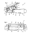
- FIG. 1 shows a discharge device 2 for dropping different guided missile 4 of an aircraft 6, the in FIG. 1
- the discharge device 2 comprises two grippers 8, which hang on a spine 10, which is fixed to a lower side of the aircraft 6.
- the grippers 8 are in FIG. 1 shown in two different states. Above and on the backbone 10 hanging the arms 12 of the gripper 8 are wide open so that the missile 4 can be inserted from below between the arms 12. With the aid of a motor 14 in each gripper 8, which are controlled by a control means 16 in the backbone 10 or in the aircraft 6, the arms 12 are then closed, so that they, for example, directly or via in FIG. 3 shown deposits 18, 20, 22 abut the guided missile 4. This position of the arms 12 is in the lower illustration of the two grippers 8 in FIG. 1 shown.
- FIG. 2 shows a section of the missile 4 and the discharge device 2 from the side.
- a distance 24 between the two grippers is infinitely adjustable by the two grippers 8 are attached via means 26 on the spine 10, such as slides, which slide along the spine 10 and can be locked at any point of the spine 10.
- the grippers 8 can be placed on the cylindrical hull 28, which they embrace directly so that they can clamp the hull 28 in front of or behind flights 30 in such a way that the guided missile 10 hangs balanced in the discharge device 2.
- the ejection device 2 also includes a data interface 32 with a slide 34, which is also slidably mounted in the longitudinal direction 38 of the guided missile 4 along the spine 10.
- a plug 38 is in terms of data technology connected to the slider 34 and thereby to the control means 16, which can be plugged into a corresponding interface 40 of the guided missile 4. In this way, guided missiles 4 can be connected to interfaces 40 at different locations in a simple manner with the control means 16.
- the grippers 8 In order to prevent a displacement of the hull 28 in the longitudinal direction 36 in the grippers 8, they are provided with a bore, not shown, into which engages an unillustrated pin which protrudes from the cylindrical body 28.
- the recess is inserted into a middle segment 50 of the gripper 8 between the two arms 12 so that it remains immovable relative to the trunk 28 when the arms 12 are opened or closed.
- the bolt can be inserted from below into the recess of the gripper 8 and the arms 12 can be closed. Conversely, the arms 12 can be opened and the guided missile 4 drops down and the bolt is released from the recess.
- FIG. 3 It is illustrated how one of the grippers 8 holds three different guided missiles 4 with the aid of different inserts 18, 20, 22.
- the gripper 8 is shown from the front, wherein both the missile 4 and the inserts 18, 20, 22 are shown cut.
- the inserts 18, 20, 22 protrude beyond the gripper 8 on both sides, ie to the front and to the rear, so that a large contact surface on the fuselage 28 of the guided missile 4 is created by them.
- a very large guided missile 4 with a large cylindrical diameter is held by the gripper 8.
- an insert 18 is in each arm 12 of the gripper 8 is engaged, the outer contour is designed so that they can be snapped into openings 42 of the arms. With the arms 12 open and the steering missile 4 not clamped, the inserts 18 are thereby fixedly attached to the gripper 8, so that the guided missile 4 can now be inserted from below between the arms 12 and the arms can be closed by means of the motor 14.
- the cylindrical inner surfaces of the two deposits 18 attach to a large area of the fuselage 28 of the missile 4 and keep it safely between the two arms 12. Since the hull 28 is very large and protrudes down a bit over the arms 12, too the deposits on the arms 12 downwardly projecting designed so that slipping out of the Lankflug stresses 4 from the arms 12 down safely prevented.
- the inserts 18, 20, 22 are made of a composite material made of plastic and metal, on the one hand is very dimensionally stable, so that the lower ends 44 of the inserts 18 are very stable and keep the missile 4 safe.
- the inner surfaces are made entirely of plastic, so that the surface of the fuselage 28 does not scratch even when displaced within the inserts 18.
- a slightly smaller LankflugMech 4 is held with a smaller cylindrical trunk 28 of the arms 12.
- the inner surface of the insert 20 is cylindrical and adapted to the diameter of the missile 4.
- the insert 20 is latched into the openings 42 of the arms 12 and can be released after use by a special tool or by hand with a pressure from the outside of the arms 12, so that other deposits in the arms 12 are inserted ,
- FIG. 3 shows how the gripper 8 holds a very thin hull 28 which is almost completely encompassed by the inserts 22 and the arms 12.
- FIG. 4 shows further examples for holding guided missiles 4, which carry a so-called hanger 46.
- the grippers 8 are also suitable for clamping the hangers 46, either directly as in the left-hand illustration of FIG FIG. 4 or deposits 48 placed around the hanger 46 and allow high pressure of the arms 12 against the hanger 46 without material deformation on the arms 12 or hanger 46.
- the arms 12 are placed around the missile 8, for example, as in FIG. 1 is shown.
- the motor 14 can now be adjusted by means of the control means 18, the contact pressure of the arms 12 on the fuselage 28.
- the contact pressure can be specified to the control means 16 from the outside or the control means 16 calculates the contact pressure independently, for example on the basis of the opening angle of the arms 12 applied to the fuselage 28.
- an unillustrated securing means is inserted between the central segment 50 and the arms 12 so that they are blocked and can not be opened even with a motorized operation of the motor 14.
- the securing means may be a locking pin which can block the arms 12 at different opening angles to the central segment 50 and backbone 10, respectively.
- the guided missile 4 is to be dropped.
- a discharge signal from the control means 16 is passed to the gripper 8, so that the motor 14 can solve the securing means.
- the arms 12 are still held firmly on the hull 28, so that it continues to be trapped between the arms 12.
- the arms 12 jerk-open, driven by the motor 14, so that the guided missile 4 is released. It drops down so that the cable between the plug 38 and the position means 34 breaks off or the plug 38 is pulled out of the interface 40. This is registered by the guided missile 4, which then starts its engine and independently flies to a destination.
- the grippers can each contain an active agent 52, for example in the form of a pyrotechnic propellant, which exerts a pressure on the missile 4 down after triggering, so that it is pushed down from the arms 12 and leaves them faster.
- the control means 16 can give a signal to the active means 52, so that these triggering, while the arms 12 are closed. Due to the strong pressure on the guided missile 4, the still closed but unlocked arms 12 are pressed apart so that they release the guided missile 4. As a result, a very coordinated opening movement of the arms 12 and the triggering of the active agent 52 is achieved.
- the arms 12 can first be opened in response to the signal from the control means 16 and, after a defined period of time after the opening signal, trigger the active means 52. It is also possible to couple the triggering of the active means 52 to an opening angle of the arms 12.
- the motor 14 forms a release means for releasing the arms 12 from a gripped locked position and the discharge of the missile.
- the control means 16 and the active agent 52 may also be components of the discharge means.
- FIG. 5 Another embodiment of a gripper 54 is shown in FIG FIG. 5 shown.
- the arms 56 of the gripper 54 consist of three members 58, 60, 62, which are mutually movable.
- the lowermost member 62 can be moved separately from the middle member 60 and separate from the uppermost member 58, as indicated by the dashed positions.
- the member 62 may be connected to the member 60 by a ratchet-type mechanism, so that the lower member 62 engages in a plurality of positions when pressed against the missile 4 and can not be moved outward again.
- the middle member 60 may be attached to the upper member 58.
- different links 60, 62 may be inserted into the links 58, e.g. In fixed and non-variable positions of the links 58, 60, 62 to each other.
- An adaptation of the gripper 54 to different missiles can be achieved by the choice of corresponding preformed members 60, 62, whose shape is adapted to the outer shape of different missiles.
- the links 60, 62 are latchingly inserted into the links 58 and the arms 56 are closed by the motor 14 and pressed against the fuselage 28.
- FIG. 6 Yet another embodiment of a gripper 64 is In Fig. 6 shown.
- the arms 66 of the gripper 64 each have their own axis of rotation about which they can be pivoted independently.
Landscapes
- Engineering & Computer Science (AREA)
- Aviation & Aerospace Engineering (AREA)
- Aiming, Guidance, Guns With A Light Source, Armor, Camouflage, And Targets (AREA)
Applications Claiming Priority (1)
| Application Number | Priority Date | Filing Date | Title |
|---|---|---|---|
| DE102010008729A DE102010008729A1 (de) | 2010-02-20 | 2010-02-20 | Flugkörperabwurfvorrichtung |
Publications (2)
| Publication Number | Publication Date |
|---|---|
| EP2361831A2 true EP2361831A2 (fr) | 2011-08-31 |
| EP2361831A3 EP2361831A3 (fr) | 2017-06-14 |
Family
ID=44012426
Family Applications (1)
| Application Number | Title | Priority Date | Filing Date |
|---|---|---|---|
| EP11001246.5A Withdrawn EP2361831A3 (fr) | 2010-02-20 | 2011-02-16 | Dispositif de largage de corps volant |
Country Status (2)
| Country | Link |
|---|---|
| EP (1) | EP2361831A3 (fr) |
| DE (1) | DE102010008729A1 (fr) |
Cited By (6)
| Publication number | Priority date | Publication date | Assignee | Title |
|---|---|---|---|---|
| CN105173086A (zh) * | 2015-08-16 | 2015-12-23 | 邢永安 | 一种固定翼航模的改装导弹用挂架 |
| WO2018072654A1 (fr) * | 2016-10-21 | 2018-04-26 | 北京京东尚科信息技术有限公司 | Support de déchargement automatique et véhicule aérien sans pilote |
| CN110239718A (zh) * | 2019-07-23 | 2019-09-17 | 安徽天路航空科技股份有限公司 | 一种航空器外挂式物品抛投装置 |
| WO2020032900A1 (fr) * | 2018-08-08 | 2020-02-13 | Tusas- Turk Havacilik Ve Uzay Sanayii Anonim Sirketi | Mécanisme de support |
| CN114087930A (zh) * | 2021-10-09 | 2022-02-25 | 湖北航天技术研究院总体设计所 | 一种多连杆导弹限位装置 |
| CN114313271A (zh) * | 2022-01-04 | 2022-04-12 | 复旦大学 | 一种可载弹多旋翼无人机 |
Families Citing this family (5)
| Publication number | Priority date | Publication date | Assignee | Title |
|---|---|---|---|---|
| CN105667794B (zh) * | 2016-03-19 | 2017-09-26 | 佛山市安尔康姆航空科技有限公司 | 无人飞行器投弹系统 |
| DE102017009671A1 (de) | 2016-11-03 | 2018-05-03 | Diehl Defence Gmbh & Co. Kg | Verfahren zum Abwerfen eines Flugkörpers |
| CN110654544B (zh) * | 2019-11-15 | 2024-05-07 | 中国工程物理研究院总体工程研究所 | 位置可调的无人机机载微小型导弹投放分离装置 |
| CN111003185B (zh) * | 2019-12-26 | 2022-11-22 | 中国航空工业集团公司西安飞机设计研究所 | 一种无人机存储投放一体化装置及存储投放方法 |
| TR2021015322A1 (tr) * | 2021-09-30 | 2023-04-24 | Tusas Tuerk Havacilik Ve Uzay Sanayii Anonim Sirketi | Bir kilitleme mekanizması. |
Family Cites Families (6)
| Publication number | Priority date | Publication date | Assignee | Title |
|---|---|---|---|---|
| CH327768A (fr) * | 1954-05-20 | 1958-02-15 | Brevets Aero Mecaniques | Engin de combat équipé d'au moins une fusée suspendue |
| FR1417343A (fr) * | 1964-10-02 | 1965-11-12 | Alkan R & Cie | Dispositif pour le transport et le largage de charges sans anneau, particulièrement en aéronautique |
| DE1506069B1 (de) * | 1966-03-29 | 1969-11-20 | Northrop Corp | Befestigungs- und Abwurfvorrichtung fuer Lasten an Luftfahrzeugen |
| DE2550587C3 (de) * | 1975-11-11 | 1979-03-08 | Messerschmitt-Boelkow-Blohm Gmbh, 8000 Muenchen | Vorrichtung zum Auswerfen von als Transport- und AbschuBbehälter für Flugkörper dienenden Behältern |
| FR2364166A1 (fr) * | 1976-09-08 | 1978-04-07 | Rafaut & Cie | Dispositif pour emporter et ejecter une charge sous avion ou helicoptere |
| FR2418743A1 (fr) * | 1978-03-01 | 1979-09-28 | Alkan R & Cie | Dispositif a pinces effacables pour le transport et l'ejection de charges sans anneau emportees sous avion |
-
2010
- 2010-02-20 DE DE102010008729A patent/DE102010008729A1/de not_active Withdrawn
-
2011
- 2011-02-16 EP EP11001246.5A patent/EP2361831A3/fr not_active Withdrawn
Non-Patent Citations (1)
| Title |
|---|
| None |
Cited By (11)
| Publication number | Priority date | Publication date | Assignee | Title |
|---|---|---|---|---|
| CN105173086A (zh) * | 2015-08-16 | 2015-12-23 | 邢永安 | 一种固定翼航模的改装导弹用挂架 |
| CN105173086B (zh) * | 2015-08-16 | 2017-03-22 | 启东市机关液化气有限责任公司 | 一种固定翼航模的改装导弹用挂架 |
| WO2018072654A1 (fr) * | 2016-10-21 | 2018-04-26 | 北京京东尚科信息技术有限公司 | Support de déchargement automatique et véhicule aérien sans pilote |
| US11345051B2 (en) | 2016-10-21 | 2022-05-31 | Beijing Jingdong Shangke Information Technology Co., Ltd. | Automatic unloading carrier and unmanned aerial vehicle |
| WO2020032900A1 (fr) * | 2018-08-08 | 2020-02-13 | Tusas- Turk Havacilik Ve Uzay Sanayii Anonim Sirketi | Mécanisme de support |
| US11434006B2 (en) | 2018-08-08 | 2022-09-06 | Tusas—Turk Havacilik Ve Uzay Sanayii Anonim Sirketi | Support mechanism |
| EP3841014A4 (fr) * | 2018-08-08 | 2022-09-14 | Tusas- Turk Havacilik Ve Uzay Sanayii Anonim Sirketi | Mécanisme de support |
| CN110239718A (zh) * | 2019-07-23 | 2019-09-17 | 安徽天路航空科技股份有限公司 | 一种航空器外挂式物品抛投装置 |
| CN110239718B (zh) * | 2019-07-23 | 2024-03-22 | 安徽天路航空科技股份有限公司 | 一种航空器外挂式物品抛投装置 |
| CN114087930A (zh) * | 2021-10-09 | 2022-02-25 | 湖北航天技术研究院总体设计所 | 一种多连杆导弹限位装置 |
| CN114313271A (zh) * | 2022-01-04 | 2022-04-12 | 复旦大学 | 一种可载弹多旋翼无人机 |
Also Published As
| Publication number | Publication date |
|---|---|
| DE102010008729A1 (de) | 2011-08-25 |
| EP2361831A3 (fr) | 2017-06-14 |
Similar Documents
| Publication | Publication Date | Title |
|---|---|---|
| EP2361831A2 (fr) | Dispositif de largage de corps volant | |
| DE602004005957T2 (de) | Vorrichtung zur Entfaltung und Steuerung der Steuerflächen eines Projektils | |
| DE3872181T2 (de) | Vorrichtung zum ausspreizen der leitfluegel eines geschosses. | |
| DE3234268C2 (fr) | ||
| DE69306462T2 (de) | Klappleitwerk zum Entfalten bei der Beschleunigung | |
| DE68904453T2 (de) | Flugvehikel mit zumindest einer abwerfbaren antriebseinheit. | |
| EP0185852B1 (fr) | Missile sans pilote | |
| EP3176079A1 (fr) | Groupe propulseur pour deltaplane | |
| WO2003067176A1 (fr) | Projectile destine a etre ejecte hors d'un tube et pourvu d'ailettes stabilisatrices sur-calibrees | |
| DE1918359A1 (de) | Flugzeug-Schleudersitz | |
| DE1256112B (de) | Vorrichtung zur Befestigung eines strahlgetriebenen Geschosses in einem als Transportbehaelter oder als Abschussrampe dienenden Gehaeuse | |
| DE102007002948A1 (de) | Vorrichtung zur Tragflächenentfaltung | |
| DE202016101049U1 (de) | Steuerungs- und Zugkraftübertragungseinrichtung für einen Lenkdrachen | |
| EP3318490B1 (fr) | Procédé d'éjection d'un missile | |
| DE69010356T2 (de) | Abwerfbares aerodynamisches Ruder. | |
| DE602004012053T2 (de) | Abwurfbare Fliegerbombe mit einer Sicherheitsvorrichtung | |
| DE2240763C2 (de) | Vorrichtung zum Abwerfen von Außenlasten von einem Flugzeug | |
| DE102016009384B4 (de) | Verfahren zum Abwurf eines Lenkflugkörpers von einer fliegenden Plattform | |
| DE2740318A1 (de) | Befestigungsvorrichtung fuer eine last an einem luftfahrzeug | |
| DE1553999A1 (de) | Einrichtung fuer den Transport und den Abschuss von Raketengeschossen mit starrem Leitwerk | |
| DE4017504A1 (de) | Entfaltungssystem fuer stromlinienfluegel | |
| EP3594610B1 (fr) | Missile | |
| DE102010031750B4 (de) | Lösbare Verbindungsanordnung zur Anbringung vo abwerfbaren Außenlasten an einem Luftfahrzeug | |
| DE102024113143B3 (de) | Greifvorrichtung mit aufeinander zu bewegbaren Greifarmen und einer Betätigungseinrichtung zum Bewegen der Greifarme | |
| DE102021102533A1 (de) | Verstellbare Rampe |
Legal Events
| Date | Code | Title | Description |
|---|---|---|---|
| PUAI | Public reference made under article 153(3) epc to a published international application that has entered the european phase |
Free format text: ORIGINAL CODE: 0009012 |
|
| AK | Designated contracting states |
Kind code of ref document: A2 Designated state(s): AL AT BE BG CH CY CZ DE DK EE ES FI FR GB GR HR HU IE IS IT LI LT LU LV MC MK MT NL NO PL PT RO RS SE SI SK SM TR |
|
| AX | Request for extension of the european patent |
Extension state: BA ME |
|
| RAP1 | Party data changed (applicant data changed or rights of an application transferred) |
Owner name: DIEHL DEFENCE GMBH & CO. KG |
|
| PUAL | Search report despatched |
Free format text: ORIGINAL CODE: 0009013 |
|
| AK | Designated contracting states |
Kind code of ref document: A3 Designated state(s): AL AT BE BG CH CY CZ DE DK EE ES FI FR GB GR HR HU IE IS IT LI LT LU LV MC MK MT NL NO PL PT RO RS SE SI SK SM TR |
|
| AX | Request for extension of the european patent |
Extension state: BA ME |
|
| RIC1 | Information provided on ipc code assigned before grant |
Ipc: B64D 1/04 20060101AFI20170510BHEP Ipc: F41F 3/06 20060101ALI20170510BHEP |
|
| STAA | Information on the status of an ep patent application or granted ep patent |
Free format text: STATUS: THE APPLICATION IS DEEMED TO BE WITHDRAWN |
|
| 18D | Application deemed to be withdrawn |
Effective date: 20171215 |