EP2361837A2 - Hochgeschwindigkeitsübertragungs-/-klebesystem - Google Patents
Hochgeschwindigkeitsübertragungs-/-klebesystem Download PDFInfo
- Publication number
- EP2361837A2 EP2361837A2 EP11001535A EP11001535A EP2361837A2 EP 2361837 A2 EP2361837 A2 EP 2361837A2 EP 11001535 A EP11001535 A EP 11001535A EP 11001535 A EP11001535 A EP 11001535A EP 2361837 A2 EP2361837 A2 EP 2361837A2
- Authority
- EP
- European Patent Office
- Prior art keywords
- label
- work
- speed
- transfer
- sensor
- Prior art date
- Legal status (The legal status is an assumption and is not a legal conclusion. Google has not performed a legal analysis and makes no representation as to the accuracy of the status listed.)
- Withdrawn
Links
Images





Classifications
-
- B—PERFORMING OPERATIONS; TRANSPORTING
- B65—CONVEYING; PACKING; STORING; HANDLING THIN OR FILAMENTARY MATERIAL
- B65C—LABELLING OR TAGGING MACHINES, APPARATUS, OR PROCESSES
- B65C9/00—Details of labelling machines or apparatus
- B65C9/40—Controls; Safety devices
- B65C9/42—Label feed control
-
- B—PERFORMING OPERATIONS; TRANSPORTING
- B65—CONVEYING; PACKING; STORING; HANDLING THIN OR FILAMENTARY MATERIAL
- B65C—LABELLING OR TAGGING MACHINES, APPARATUS, OR PROCESSES
- B65C9/00—Details of labelling machines or apparatus
- B65C9/08—Label feeding
- B65C9/18—Label feeding from strips, e.g. from rolls
- B65C9/1865—Label feeding from strips, e.g. from rolls the labels adhering on a backing strip
Definitions
- the present invention relates to a high-speed label transfer/sticking system that transfers each separated one of labels having information printed thereon by a label printer to a labeling position at a high speed synchronously with an object transferred separately from the label and to which the label is to be stuck and sticks the label to the object
- 2009-62087 discloses a technique of separating, from a carrying base, each of labels having information printed thereon by a printer, putting it onto a plurality of endless rubber belts and transferring it horizontally to a labeling position.
- the conventional label printer designed to print required information on a label just before labeling should be used in combination with a device designed to transfer each separated one of labels having the information printed thereon by a label printer by a label transfer unit capable of transferring the label at a speed corresponding to the transfer speed of a conveyor to carry a work and stick the label to the work efficiently without bringing the label transfer unit and work conveyor down.
- a high-speed label transfer/sticking system capable of detecting a work transferred by a work conveyor, then printing information such as a bar code, date, etc. different from one work to another on each label by a label printer, transferring each separated one of the labels by a label transfer unit, of which the carrying speed can be variably controlled correspondingly to the transfer speed of the work conveyor, while holding the label adsorbed on the label transfer unit, and sticking the label to the work precisely in a labeling position efficiently with the label transfer unit and work conveyor not brought down.
- a high-speed label transfer/sticking system including a label printer to deliver a printed and separated label, a sensor to detect the delivered label, a label transfer unit formed from an endless adsorption belt disposed near the downstream side of the label printer, a work sensor to detect the position to which a work has been carried, a calculating device which, supplied with a detection signal from the work sensor, calculates a position of the work, a forward end position of the label and a target labeling position, and a controller to control, based on the information calculated by the calculating unit, the speed of the label transfer unit variably correspondingly to the work transfer speed of a work conveyor.
- the adsorption belt of the label transfer unit is formed from two adsorption belts, and a label presser is provided at the forward of the label transfer unit and between the two adsorption belts to press the label to the work.
- the label presser includes an abutment portion that is biased by a biasing unit outwardly from the forward end of the label transfer unit, thus put into abutment with the work and forced back toward the forward end of the label transfer unit against the force of the biasing portion correspondingly to the thickness of the work, the abutment of the abutment portion with the work causing the label to be pressed to the work.
- the label transfer/sticking system according to the present invention is applicable to a well-known label printer incorporating a printer and a peeling block which separates each of labels without any modification.
- the label is transferred on the endless adsorption belt under a negative pressure, and the label-transferring adsorption belt is variably controllable in driving speed correspondingly to the speed of a work being transferred separately on a work conveyor for synchronization with the work carrying speed at the time of labeling.
- the present invention allows precise labeling irrespectively of the work carrying speed.
- each of labels having information printed thereon by the label printer can be transferred at a high speed to the labeling position and stuck to a work, information printing by the label printer can be retried even if any label cannot be successfully stuck. Thus, no label goes to waste because no other printed label will stand by. Accordingly, each of labels having printed thereon information different from one work to another can be stuck to a work at a high speed.
- FIGS. 1 and 2 schematically show the construction of the high-speed label transfer/sticking system according to the first embodiment of the present invention.
- the reference numeral 1 indicates a well-known label printer.
- each label L is fed being carried on a release paper through a printing post 2 to a peeling block 4 provided with a sharp edge 3 at the outlet of the label printer 1.
- the release paper is folded back by the peeling block 4 and the label L is let out of a label ejector 5.
- the label printer 1 since the construction of the label printer 1 is well-known, it will not be described in detail.
- the reference numeral 6 indicates a labeler which transfers a label.
- the labeler 6 includes a roller 7 provided near the label printer 1, a roller 9 provided near a work conveyor 8, an endless adsorption belt 10 extended between and around the rollers 7 and 9, and a drive roller 11 which drives the endless belt 10.
- the reference numeral 12 indicates a drive motor to drive the labeler 6.
- the adsorption belt 10 is of a flat type and has a plurality of suction holes (best shown with a reference number 10c in FIG. 9 ) longitudinally formed in the surface thereof at predetermined intervals and through which the label L is adsorbed to the adsorption belt 10 under a negative pressure produced by a blower (not shown).
- the endless adsorption belt 10 is always applied with the negative pressure.
- the reference numeral 13 indicates a tension roller and 14 indicates a driven roller. The tension roller 13 and driven roller 14 work together to tense the adsorption belt 10.
- a sensor 15 is provided below the label ejector 5 of the label printer 1 to detect a label L having been delivered. Detecting the rear end of the delivered label L, the sensor 15 sends a delivered-label detection signal to a controller 30.
- the controller 30 includes a calculation device 31.
- a work sensor 16 is provided in an appropriate place along the path of the work conveyor 8 to detect a position to which a work W has been transferred and send a detected position of the work W to the controller 30.
- a drive motor 17 and conveyor driving unit 18 are provided to drive the work conveyor 8. Near the front end of the labeler 6 there is also provided a secondary pressing roller 19 to support a label L being stuck to a work W.
- the first air blow nozzle 20 is located below the label ejector 5 to give air blow to an ejected label L from below for smooth transition of the label L to the labeler 6.
- the second air blow nozzle 21 is located near a labeling position to blow air obliquely from above to the label L having been transferred by the labeler 6 for transition of the label L to the surface of the work W.
- the label L is in a position under the roller 9 where the suction holes in the adsorption belt 10 are closed by the roller 9 and thus no more negative pressure will be applied to the label L through the suction holes.
- the label L will be released from the belt 10 and transferred to the surface of the work W under the effect of the air blow from the air blow nozzle 21.
- encoders 22 and 23 are provided in the apparatus. However it should be noted that sensors to detect light pulses etc. are not illustrated herein.
- the encoder 22 is used to detect the running direction of the drive motor 12 which drives the adsorption belt 10, and the moving distance and rotation speed of the belt 10.
- the encoder 23 is used to detect the running direction of the drive motor 17 which drives the work conveyor 8, and the moving distance and speed of the work.
- the aforementioned controller 30 is constructed as shown in FIG. 3 for example.
- the controller 30 includes a counter 30a to count pulses from the encoder 23, a circuit 30b to detect the conveyor speed, a circuit 30c to hold a detected position of the work, and a calculating circuit 30d to determine a present position of the work.
- the controller 30 further includes a circuit 30e to correct the timing of label delivery according to a preset time of label delivery, and a work-detection holding relay 30f to supply an instruction for delivery of a label to the label printer 1 after the work is carried.
- the result of detection from the conveyor speed detection circuit 30b is used to synchronize the speed at which the labeler 6 transfers the label L with the conveyor speed.
- the detection result from the conveyor speed detection circuit 30b is also used to adjust the timing when an instruction for delivering a label is supplied.
- the detected work position holding circuit 30c holds a value counted by the counter 30a at the moment when a work W is detected by the work sensor 16 until the work W passes by the labeling position A.
- the present work position calculating circuit 30d determines the moving distance of the work W by calculating a difference between the value counted by the counter 30a at the moment when the work sensor 16 has detected the work W and a present count in the counter 30a.
- the controller 30 includes also a target position calculating circuit 30g to determine a target position where a label L is to be stuck on the basis of a distance (Lph) from the work sensor 16 to the labeling position on the work W and a adjustment distance (Pp) for labeling on the work W, and a comparison circuit 30h which makes comparison between the target position and a position at which passage of the work W has been checked to judge whether the work W has passed or not.
- a target position calculating circuit 30g to determine a target position where a label L is to be stuck on the basis of a distance (Lph) from the work sensor 16 to the labeling position on the work W and a adjustment distance (Pp) for labeling on the work W
- Pp adjustment distance
- the controller 30 further includes a counter 30i to count pulses from the encoder 22, a circuit 30j to detect the belt speed of the labeler 6, a circuit 30k to hold a position where a label L has been delivered, and a calculation circuit 301 to determine a present position of the label L.
- the controller 30 includes a calculation circuit 30m to determine the forward end position of the label L on the basis of a distance (Lchk) from the delivered label sensor 15 to a position where the label L is to be stuck and the length of the label L (Ls), and a subtracter 30n to subtract the target position from the forward end position of the label L.
- the label delivery-position holding circuit 30k holds a value counted by the counter 30i at the moment when the sensor 15 detects the rear end of the delivered label L until the work W passes by the labeling position A.
- the label present position calculation circuit 301 adds the present count in the counter 30i to the value counted by the counter 30i at the moment when the sensor 15 detects the rear end of the delivered label L to determine a moving distance of the label L.
- the label forward-end position calculation circuit 30m calculates a difference between the value counted by the counter 30i at the moment when the sensor 15 detects the rear end of the label L and present count in the counter 30i to determine a moving distance of the label L.
- the controller 30 further includes a position controlling calculation circuit 30o to determine, based on a value supplied from the subtracter 30n, a value for controlling the forward end position of the label L, a position control relay 30p to provide a value for controlling the forward end position, an adder 30q to add the forward-end position controlling value and above-mentioned conveyor speed, and a work detecting/holding relay 30r to hold the position of a work W based on the output from the adder 30q and provide a speed command through a speed control circuit 30s.
- a position controlling calculation circuit 30o to determine, based on a value supplied from the subtracter 30n, a value for controlling the forward end position of the label L
- a position control relay 30p to provide a value for controlling the forward end position
- an adder 30q to add the forward-end position controlling value and above-mentioned conveyor speed
- a work detecting/holding relay 30r to hold the position of a work W based on the output from the adder 30q and provide a
- the position controlling calculation circuit 30o controls the carrying speed of the label L so that the label L and work W coincide in relative position with each other.
- the speed control circuit 30s provides such control that in case the control value for coincidence in relative position between the label L and work W exceeds a predetermined upper or lower limit, it will fall within the range between these limits.
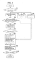
- the high-speed label transfer/sticking system operates as will be described below with reference to the flow chart shown in FIG. 4 .
- the label printer 1 itself has a well-known construction, and so its operation will not be described in detail herein.
- step S1 When the work sensor 16 detects a work W to be carried on the work conveyor 8 (in step S1), timing of delivering a label L is adjusted (in step S2). This label-delivery timing is adjusted such that Ld is equal to Wd + Pp even if the work W is carried at any other speed as will be explained with reference to FIG. 6 later.
- Ld is a distance from the forward end of the label L to the labeling position A
- Wd is a distance from the forward end of the work W to the labeling position A
- Pp is a distance for adjusting the labeling position in relation to the work W.
- Timm (Lhigh - Lcur) + Pp.
- Lhigh is a calculated moving distance of a work for a label being delivered at a maximum speed and it is determined by calculating Smax X Tprt where Smax is a maximum carrying speed in mm/sec and Tprt is a label delivery time in sec of the label printer 1.
- Lcur is a calculated moving distance of a work for a label being delivered at an actual speed and is determined by calculating Scur X Tprt where Scur is a carrying speed in mm/sec when the work is detected.
- step S2 Upon adjustment of label-delivery timing in step S2, the labeler 6 is put into operation in step S3 and position detection of a work is started in step S4.
- step S5 When the work W arrives at a position relative to the label L, which matches the delivery timing of a label L, in step S5, an instruction for delivery of a label L is supplied to the label printer 1 in step S6.
- the label printer 1 prints a bar code, date and other necessary information onto the label L. It should be noted that after such printing is made on the label L, the release paper is folded back by the sharp edge 3, opposite to the label ejector 5, of the peeling block 4 and one label L is delivered. Thus, labels are delivered one by one.
- step 7 When a detection signal is supplied from the delivered label sensor 15 provided below the label ejector 5, it is confirmed in step 7 that the label L has been delivered. Then, a target labeling position is calculated based on the position of the work W and forward end position of the label L in step S8. Driving of the adsorption belt 10 of the labeler 6 is controlled correspondingly to the target labeling position in step S9 so as to be synchronous with the transfer speed of the work conveyor 8 in the labeling position A, and labeling onto the work W is thus completed in step S10.
- the adsorption belt 10 of the labeler 6 is driven under control as will be explained below with reference to FIGS. 5 and 6 .
- the label printer 1 When a work W is detected by the work sensor 16 as shown in FIG. 5 , the label printer 1 will print necessary information onto a label L. Then, it will be checked by the delivered label sensor 15 that the label L has been delivered as shown in FIG. 6 . At this time, the work W will have been moved to the labeling position A.
- Wd + Pp ⁇ Ld or Wd + Pp > Ld Wd is a distance between the forward end of the work W and the labeling position A, Pp is a distance for adjusting the labeling position on the work W and Ld is a distance from the forward end of the label L to the labeling position A as having been described in the foregoing.
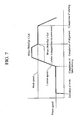
- the labeler 6 When the delivery of the label L is complete, the labeler 6 is driven as shown in FIG. 7 . Namely, in case Wd + Pp ⁇ Ld, the labeler 6 is driven once at a faster speed than the carrying speed of the work W. In case Wd + Pp > Ld, the labeler 6 is driven once at a slower speed than the carrying speed of the work W.
- the labeler 6 and work conveyor 8 are controlled for the work W and label L to coincide in relative position with each other before labeling. It should be noted that when the label L and work W coincide in relative position with each other, the label and work speeds become equal to each other and controlled for synchronization until the label L is stuck to the work W.
- the controller 30 controls the transfer speed of the label L variably based on each of the position of the work W, forward end position of the label L and target labeling position of the label L so as to match the transfer speed of the work W on the work conveyor 8.
- the label L can be stuck precisely irrespectively of the transfer speed of the work W.
- FIGS. 8 and 9 schematically illustrate the overall structure of a second embodiment of the present invention which is different in construction from the first embodiment of the label transfer/sticking system shown in FIGS. 1 and 2 .
- elements which are the same as those in the first embodiment will be referred to using the same reference numerals having been used in the foregoing description of the first embodiment and will not further be explained.
- the second embodiment is different from the high-speed label transfer/sticking system according to the first embodiment shown in FIGS. 1 and 2 in that it further includes a label presser 40 to press a label to the labeling position A at the forward end of the labeler 6. It is also different from the first embodiment shown in FIGS. 1 and 2 in that as will be known from FIG. 9 , two adsorption belts 10a and 10b are used instead of the endless adsorption belt 10 shown in FIGS. 1 and 2 .
- the belts 10a and 10b have suction holes 10c formed therein as shown in FIG. 9 .
- the suction holes 10a and 10b are provided to let the label L cling closely to the belts 10a and 10b under the effect of a negative pressure.
- the second embodiment is the same in construction as the first embodiment shown in FIGS. 1 and 2 .
- the label presser 40 is provided between the adsorption belts 10a and 10b so as to be protruded and retracted relative to the surface of the work conveyor 8 when the labeler 6 is turned on and off, respectively. Also, the label presser 40 is variable in position correspondingly to the thickness of a work W when the labeler 6 is going to stick a label to the work W.
- the label presser 40 will be explained in further detail below.
- the label presser 40 includes a label pressing member 41 and a pressing-member biasing member 46 as shown in FIGS. 10 and 11 .
- the label pressing member 41 includes a body 44 supported pivotally on a shaft 42 and having an abutment portion 43 formed at a part of the circumference thereof and which is to abut on the work W, and a pressing lever 45 formed integrally with the pivotal body 44 to project upward.
- the pressing-member biasing member 46 includes a rotary cylinder 47, a tension spring 48 of which one end 48a is engaged on the pressing lever 45 and the other end 48b is engaged on the rotary cylinder 47, and a cam 49 installed on a rotary shaft 47a.
- the label L having been adsorbed to the adsorption belts 10a and 10b under the negative pressure is released from the belts 10a and 10b, pressed to the work W by the abutment portion 43 of the label pressing member 41 and further pressed to the work W by the secondary pressing roller 19, whereby the label L is positively stuck to the work W.
- the abutment portion 43 of the label presser 40 is biased by the tension spring 48 in a direction in which it is forced out from the forward end of the labeler 6.
- the tension spring 48 When the abutment portion 43 abuts on the work W, it is forced back toward the forward end of the labeler 6 against the force of the tension spring 48 correspondingly to the thickness of the work W. Namely, as the abutment portion 43 abuts on the work W, the label L is pressed to the work W. Even if the works W are different in thickness from one another, the label L can be positively stuck to each of such works W.
- the high-speed label transfer/sticking system according to the present invention can be arbitrarily used in combination with an existing label printer, it can be freely installed in the labeling process in existing factories or the like and applied widely.
Landscapes
- Labeling Devices (AREA)
- Delivering By Means Of Belts And Rollers (AREA)
Applications Claiming Priority (2)
| Application Number | Priority Date | Filing Date | Title |
|---|---|---|---|
| JP2010041481 | 2010-02-26 | ||
| JP2010192053A JP2011195197A (ja) | 2010-02-26 | 2010-08-30 | ラベル高速移送貼着装置 |
Publications (2)
| Publication Number | Publication Date |
|---|---|
| EP2361837A2 true EP2361837A2 (de) | 2011-08-31 |
| EP2361837A3 EP2361837A3 (de) | 2013-04-03 |
Family
ID=44072541
Family Applications (1)
| Application Number | Title | Priority Date | Filing Date |
|---|---|---|---|
| EP11001535A Withdrawn EP2361837A3 (de) | 2010-02-26 | 2011-02-24 | Hochgeschwindigkeitsübertragungs-/-klebesystem |
Country Status (4)
| Country | Link |
|---|---|
| US (1) | US20110209831A1 (de) |
| EP (1) | EP2361837A3 (de) |
| JP (1) | JP2011195197A (de) |
| CN (1) | CN102167179A (de) |
Cited By (3)
| Publication number | Priority date | Publication date | Assignee | Title |
|---|---|---|---|---|
| EP3131821A4 (de) * | 2014-04-16 | 2017-11-15 | Autolabel AB | Verfahren zur etikettenapplikation und vorrichtung zur durchführung davon |
| WO2020109575A3 (en) * | 2018-11-30 | 2020-08-06 | Dover Europe Sarl | Applicator apparatus and method |
| US11434036B2 (en) | 2020-01-27 | 2022-09-06 | Dover Europe Sàrl | Label application system |
Families Citing this family (20)
| Publication number | Priority date | Publication date | Assignee | Title |
|---|---|---|---|---|
| CN102633027A (zh) * | 2012-05-09 | 2012-08-15 | 大亚人造板集团有限公司强化地板分公司 | 一种新型贴标机 |
| CN102936180B (zh) * | 2012-07-04 | 2015-11-25 | 王玉首 | 雷管编码与贴标装置及方法 |
| GB2519372B (en) * | 2013-10-21 | 2020-06-03 | Videojet Technologies Inc | Machine and method of operation |
| KR101731863B1 (ko) * | 2015-04-20 | 2017-05-04 | 신한포장(주) | 합지장치 |
| US9809730B2 (en) * | 2015-06-10 | 2017-11-07 | Upm Raflatac Oy | Printable label comprising a clear face layer and a clear adhesive layer |
| DE102015116166A1 (de) * | 2015-09-24 | 2017-03-30 | Espera-Werke Gmbh | Vorrichtung und Verfahren zum Etikettieren von einzelnen Produkten |
| CN105501595B (zh) * | 2015-12-18 | 2019-06-28 | 同方威视技术股份有限公司 | 标签施加装置和方法 |
| JP6707383B2 (ja) * | 2016-03-31 | 2020-06-10 | 株式会社フジシール | ラベル装着装置 |
| CN106945898A (zh) * | 2017-04-02 | 2017-07-14 | 青岛北琪实业有限公司 | 一种自动条码识别装置及其使用方法 |
| CN106966007A (zh) * | 2017-05-02 | 2017-07-21 | 苏州市厚宏智能科技有限公司 | 贴签方法 |
| CN108216819A (zh) * | 2018-02-27 | 2018-06-29 | 乾大新材料有限公司 | 自动贴合贴标机 |
| CN108528894A (zh) * | 2018-05-14 | 2018-09-14 | 深圳市德仓科技有限公司 | 一种上料设备及贴标机 |
| DE102018207469A1 (de) * | 2018-05-15 | 2019-11-21 | Tesa Se | Stanzlingsapplikator und Verfahren zur Applikation eines Stanzlings |
| CN109850296A (zh) * | 2018-10-24 | 2019-06-07 | 苏州天华超净科技股份有限公司 | 全自动贴标机及其贴标方法 |
| JP7424082B2 (ja) * | 2020-01-31 | 2024-01-30 | ブラザー工業株式会社 | ラベル巻付装置 |
| CN113120369A (zh) * | 2021-03-31 | 2021-07-16 | 杭州丙甲科技有限公司 | 辊压式平面贴标机构及其控制方法 |
| CN113602889A (zh) * | 2021-08-03 | 2021-11-05 | 辽宁鑫硕智能机械有限公司 | 保温棉条上料自动追踪贴棉方法 |
| JP2023106994A (ja) * | 2022-01-21 | 2023-08-02 | オムロン株式会社 | シール貼り付けシステム、シール貼り付けシステムにより実行される方法、およびシール貼り付けシステムにより実行されるプログラム |
| CN115072121A (zh) * | 2022-06-30 | 2022-09-20 | 广东紫泉标签有限公司 | 高精度的快速贴标设备 |
| CN116443382A (zh) * | 2023-04-26 | 2023-07-18 | 广东高臻智能装备有限公司 | 贴标设备、贴标设备的控制方法及存储介质 |
Citations (2)
| Publication number | Priority date | Publication date | Assignee | Title |
|---|---|---|---|---|
| JPH06239325A (ja) | 1993-02-04 | 1994-08-30 | Osaka Sealing Insatsu Kk | ラベル移送貼付装置 |
| JP2009062087A (ja) | 2007-09-07 | 2009-03-26 | Toshiba Tec Corp | プリンタラベラ装置及びラベラ |
Family Cites Families (18)
| Publication number | Priority date | Publication date | Assignee | Title |
|---|---|---|---|---|
| US4294644A (en) * | 1980-01-30 | 1981-10-13 | Datafile Limited | Servo motor control labeller |
| DE3019506C2 (de) * | 1980-05-22 | 1983-12-22 | Max H. 4901 Hiddenhausen Klinger | Etikettiervorrichtung |
| US4366023A (en) * | 1981-09-08 | 1982-12-28 | Njm, Inc. | Mechanism for applying labels and the like |
| US4556443A (en) * | 1983-03-11 | 1985-12-03 | Avery International Corporation | Air shuttle label dispenser |
| US5256239A (en) * | 1991-05-03 | 1993-10-26 | New Jersey Machine Inc. | Continously moving web pressure-sensitive labeler |
| US5399228A (en) * | 1992-02-21 | 1995-03-21 | Best Label Co., Inc. | Apparatus and method for automatically applying adhesive-backed labels to moving articles |
| US5560293A (en) * | 1994-09-26 | 1996-10-01 | Moore Business Forms, Inc. | Linerless label printer and transport system |
| US5888343A (en) * | 1995-09-05 | 1999-03-30 | Fingerhut Corporation | Labeling apparatus and method |
| JPH10139025A (ja) * | 1996-11-11 | 1998-05-26 | Fuji Photo Film Co Ltd | ラベル貼着システム |
| US6558490B2 (en) * | 1997-10-06 | 2003-05-06 | Smyth Companies, Inc. | Method for applying labels to products |
| EP0934884A1 (de) * | 1998-02-05 | 1999-08-11 | Gärtnereibedarf Asperg eG | Vorrichtung zum Etikettieren von Gegenständen |
| US6428639B1 (en) * | 1999-07-19 | 2002-08-06 | Krones, Inc. | Computer controlled position slaved servo labeling system |
| AUPS171602A0 (en) * | 2002-04-12 | 2002-05-23 | 3M Innovative Properties Company | Labelling device |
| US6841018B2 (en) * | 2002-06-28 | 2005-01-11 | Thomas Pituch | Label reconciliation device and method |
| JP4322557B2 (ja) * | 2003-05-29 | 2009-09-02 | 株式会社サトー | ラベル貼付装置 |
| JP2005280821A (ja) * | 2004-03-31 | 2005-10-13 | Sato Corp | ラベル貼付装置 |
| JP2005335729A (ja) * | 2004-05-25 | 2005-12-08 | Teraoka Seiko Co Ltd | ラベル貼付装置 |
| US20060237125A1 (en) * | 2005-04-26 | 2006-10-26 | Montgomery Bruce G | Method and apparatus for applying labels to documents |
-
2010
- 2010-08-30 JP JP2010192053A patent/JP2011195197A/ja not_active Withdrawn
-
2011
- 2011-02-22 US US13/031,901 patent/US20110209831A1/en not_active Abandoned
- 2011-02-23 CN CN201110047255XA patent/CN102167179A/zh active Pending
- 2011-02-24 EP EP11001535A patent/EP2361837A3/de not_active Withdrawn
Patent Citations (2)
| Publication number | Priority date | Publication date | Assignee | Title |
|---|---|---|---|---|
| JPH06239325A (ja) | 1993-02-04 | 1994-08-30 | Osaka Sealing Insatsu Kk | ラベル移送貼付装置 |
| JP2009062087A (ja) | 2007-09-07 | 2009-03-26 | Toshiba Tec Corp | プリンタラベラ装置及びラベラ |
Cited By (4)
| Publication number | Priority date | Publication date | Assignee | Title |
|---|---|---|---|---|
| EP3131821A4 (de) * | 2014-04-16 | 2017-11-15 | Autolabel AB | Verfahren zur etikettenapplikation und vorrichtung zur durchführung davon |
| WO2020109575A3 (en) * | 2018-11-30 | 2020-08-06 | Dover Europe Sarl | Applicator apparatus and method |
| US11370574B2 (en) | 2018-11-30 | 2022-06-28 | Dover Europe Sàrl | Applicator apparatus and method |
| US11434036B2 (en) | 2020-01-27 | 2022-09-06 | Dover Europe Sàrl | Label application system |
Also Published As
| Publication number | Publication date |
|---|---|
| JP2011195197A (ja) | 2011-10-06 |
| CN102167179A (zh) | 2011-08-31 |
| US20110209831A1 (en) | 2011-09-01 |
| EP2361837A3 (de) | 2013-04-03 |
Similar Documents
| Publication | Publication Date | Title |
|---|---|---|
| EP2361837A2 (de) | Hochgeschwindigkeitsübertragungs-/-klebesystem | |
| DK2185426T3 (en) | Device and method for label and separation -påføring | |
| US4544431A (en) | Roll fed labelling machine | |
| EP2634105B2 (de) | Vorrichtung zur herstellung von etiketten | |
| CN109455376B (zh) | 一种药瓶贴标机 | |
| EP2450284A1 (de) | Maschine zum Anbringen von Klebeband | |
| JP4968835B2 (ja) | 多重シートの生産装置 | |
| KR100274474B1 (ko) | 라이너 없는 라벨 웨브용 플레이서 장치 및 방법 | |
| US6006669A (en) | Apparatus for affixing removable notes to a moving web | |
| EP0949178B1 (de) | Vorrichtung und Verfahren zur Befestigung von Karten auf einer sich bewegenden Bahn | |
| KR101720876B1 (ko) | 포장지 개구 스티커 리드 자동 부착 장치 | |
| JP6705490B2 (ja) | ラベルプリンタ、プログラム、及びラベル発行方法 | |
| JP2009035259A (ja) | ラベリングマシンにおける不良ラベルの排出装置 | |
| JPH10101005A (ja) | 横型製袋充填方法および装置 | |
| CN110902072A (zh) | 一种即时打印多功能贴标机 | |
| JP4117879B2 (ja) | ラベル供給装置 | |
| JP2001151214A (ja) | ラベル貼付機のラベル移送装置およびラベル移送方法 | |
| CN209535686U (zh) | 一种药瓶贴标机 | |
| JP5817121B2 (ja) | ラベルプリンタ及びラベル貼付装置 | |
| JP2012218203A (ja) | 表示ラベル作成装置 | |
| JP4493768B2 (ja) | ラベル貼付機のラベル移送装置およびラベル移送方法 | |
| JP6962610B2 (ja) | ラベルプリンタ、プログラム、及びラベル発行方法 | |
| JP4554028B2 (ja) | 注出口部材取付装置 | |
| JP3641669B2 (ja) | 定尺シートの搬送装置 | |
| JPS62275751A (ja) | 転写装置 |
Legal Events
| Date | Code | Title | Description |
|---|---|---|---|
| PUAI | Public reference made under article 153(3) epc to a published international application that has entered the european phase |
Free format text: ORIGINAL CODE: 0009012 |
|
| AK | Designated contracting states |
Kind code of ref document: A2 Designated state(s): AL AT BE BG CH CY CZ DE DK EE ES FI FR GB GR HR HU IE IS IT LI LT LU LV MC MK MT NL NO PL PT RO RS SE SI SK SM TR |
|
| AX | Request for extension of the european patent |
Extension state: BA ME |
|
| PUAL | Search report despatched |
Free format text: ORIGINAL CODE: 0009013 |
|
| AK | Designated contracting states |
Kind code of ref document: A3 Designated state(s): AL AT BE BG CH CY CZ DE DK EE ES FI FR GB GR HR HU IE IS IT LI LT LU LV MC MK MT NL NO PL PT RO RS SE SI SK SM TR |
|
| AX | Request for extension of the european patent |
Extension state: BA ME |
|
| RIC1 | Information provided on ipc code assigned before grant |
Ipc: B65C 9/42 20060101AFI20130228BHEP Ipc: B65C 9/18 20060101ALI20130228BHEP |
|
| 17P | Request for examination filed |
Effective date: 20131004 |
|
| RBV | Designated contracting states (corrected) |
Designated state(s): AL AT BE BG CH CY CZ DE DK EE ES FI FR GB GR HR HU IE IS IT LI LT LU LV MC MK MT NL NO PL PT RO RS SE SI SK SM TR |
|
| STAA | Information on the status of an ep patent application or granted ep patent |
Free format text: STATUS: THE APPLICATION IS DEEMED TO BE WITHDRAWN |
|
| 18D | Application deemed to be withdrawn |
Effective date: 20131005 |