EP2361845B1 - Distributeur pour vinaigrette - Google Patents
Distributeur pour vinaigrette Download PDFInfo
- Publication number
- EP2361845B1 EP2361845B1 EP20110156101 EP11156101A EP2361845B1 EP 2361845 B1 EP2361845 B1 EP 2361845B1 EP 20110156101 EP20110156101 EP 20110156101 EP 11156101 A EP11156101 A EP 11156101A EP 2361845 B1 EP2361845 B1 EP 2361845B1
- Authority
- EP
- European Patent Office
- Prior art keywords
- dispenser
- passage
- container
- tube
- section
- Prior art date
- Legal status (The legal status is an assumption and is not a legal conclusion. Google has not performed a legal analysis and makes no representation as to the accuracy of the status listed.)
- Not-in-force
Links
- 235000013305 food Nutrition 0.000 title claims description 57
- 230000002093 peripheral effect Effects 0.000 claims description 23
- 238000005273 aeration Methods 0.000 claims description 5
- 229920003023 plastic Polymers 0.000 claims description 5
- 239000012530 fluid Substances 0.000 claims description 4
- 229920001296 polysiloxane Polymers 0.000 claims description 4
- 229910001220 stainless steel Inorganic materials 0.000 claims description 4
- 239000010935 stainless steel Substances 0.000 claims description 4
- 239000013536 elastomeric material Substances 0.000 claims description 3
- XAGFODPZIPBFFR-UHFFFAOYSA-N aluminium Chemical compound [Al] XAGFODPZIPBFFR-UHFFFAOYSA-N 0.000 claims description 2
- 229910052782 aluminium Inorganic materials 0.000 claims description 2
- 238000004891 communication Methods 0.000 claims description 2
- 239000011521 glass Substances 0.000 claims description 2
- 235000015071 dressings Nutrition 0.000 description 46
- 239000003921 oil Substances 0.000 description 11
- 235000019198 oils Nutrition 0.000 description 11
- 239000000463 material Substances 0.000 description 3
- 239000004006 olive oil Substances 0.000 description 3
- 235000008390 olive oil Nutrition 0.000 description 3
- 238000007789 sealing Methods 0.000 description 3
- 230000007812 deficiency Effects 0.000 description 2
- 238000000034 method Methods 0.000 description 2
- 235000021419 vinegar Nutrition 0.000 description 2
- 239000000052 vinegar Substances 0.000 description 2
- OKTJSMMVPCPJKN-UHFFFAOYSA-N Carbon Chemical compound [C] OKTJSMMVPCPJKN-UHFFFAOYSA-N 0.000 description 1
- 229910052799 carbon Inorganic materials 0.000 description 1
- 239000000919 ceramic Substances 0.000 description 1
- 239000011248 coating agent Substances 0.000 description 1
- 238000000576 coating method Methods 0.000 description 1
- 239000008157 edible vegetable oil Substances 0.000 description 1
- 230000000694 effects Effects 0.000 description 1
- 235000015090 marinades Nutrition 0.000 description 1
- 238000000465 moulding Methods 0.000 description 1
- 235000014438 salad dressings Nutrition 0.000 description 1
- 238000000926 separation method Methods 0.000 description 1
- 235000013599 spices Nutrition 0.000 description 1
- 239000002699 waste material Substances 0.000 description 1
Images




Classifications
-
- B—PERFORMING OPERATIONS; TRANSPORTING
- B65—CONVEYING; PACKING; STORING; HANDLING THIN OR FILAMENTARY MATERIAL
- B65D—CONTAINERS FOR STORAGE OR TRANSPORT OF ARTICLES OR MATERIALS, e.g. BAGS, BARRELS, BOTTLES, BOXES, CANS, CARTONS, CRATES, DRUMS, JARS, TANKS, HOPPERS, FORWARDING CONTAINERS; ACCESSORIES, CLOSURES, OR FITTINGS THEREFOR; PACKAGING ELEMENTS; PACKAGES
- B65D47/00—Closures with filling and discharging, or with discharging, devices
- B65D47/04—Closures with discharging devices other than pumps
- B65D47/06—Closures with discharging devices other than pumps with pouring spouts or tubes; with discharge nozzles or passages
-
- B—PERFORMING OPERATIONS; TRANSPORTING
- B65—CONVEYING; PACKING; STORING; HANDLING THIN OR FILAMENTARY MATERIAL
- B65D—CONTAINERS FOR STORAGE OR TRANSPORT OF ARTICLES OR MATERIALS, e.g. BAGS, BARRELS, BOTTLES, BOXES, CANS, CARTONS, CRATES, DRUMS, JARS, TANKS, HOPPERS, FORWARDING CONTAINERS; ACCESSORIES, CLOSURES, OR FITTINGS THEREFOR; PACKAGING ELEMENTS; PACKAGES
- B65D81/00—Containers, packaging elements, or packages, for contents presenting particular transport or storage problems, or adapted to be used for non-packaging purposes after removal of contents
- B65D81/32—Containers, packaging elements, or packages, for contents presenting particular transport or storage problems, or adapted to be used for non-packaging purposes after removal of contents for packaging two or more different materials which must be maintained separate prior to use in admixture
- B65D81/3216—Rigid containers disposed one within the other
- B65D81/3227—Rigid containers disposed one within the other arranged parallel or concentrically and permitting simultaneous dispensing of the two materials without prior mixing
Definitions
- the present invention relates to a dispenser for dispensing food dressing that prevents the food dressing from dripping from the dispenser.
- Dispensers suitable for dispensing edible oils are known in the art.
- such dispensers are decorative and comprise a container for holding the oil and a spout through which the oil can be dispensed from the container.
- a deficiency with existing oil dispensers is that after pouring they typically drip or leave a trail of oil running down the outer edge of the dispenser. More specifically, after pouring, once the user has returned the dispenser to an upright position, a trail of oil is left to drip down the outside edge of the spout. After numerous uses, a sufficient amount of oil has dripped down the edge of the spout to cause the body of the container to be covered in oil. This not only results in a waste of oil (which can be quite expensive depending on the quality of the oil) but also creates an unpleasant greasy coating on the outside of the dispenser which can cause a user's hands and fingers to become greasy and sticky.
- a dispenser comprising all the technical features of the preamble of claim 1 is furthermore known from the document US 5511700 A1 .
- the present invention provides a dispenser for food dressing, as defined by appended claim 1.
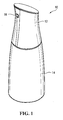
- a dispenser 10 for food dressing in accordance with a non-limiting embodiment of the present invention is shown.
- the dispenser 10 is suitable for dispensing food dressings, such as salad dressings, olive oil, oil and vinegar, oil mixed with vinegar and spices, food marinades, or any other type of edible food dressing.
- the dispenser 10 comprises a cap 12 and a container 14 that together extend along a longitudinal axis identified by reference numeral 8 in Figure 2 .
- the container 14 further comprises a bottom wall 28 and a peripheral wall 30 that define an internal space 18 for receiving a volume of food dressing, and a rim 26 that defines an opening 27 such that food dressing can exit via the opening 27.
- the container 14 may be made of transparent plastic, glass, ceramic or stainless steel, among other possibilities.
- the cap 12 comprises an attachment portion 34 for attaching the cap 12 to the container 14 for at least partially covering the opening 27.
- the attachment portion 34 of the cap 12 comprises internal threads 36 for engaging with corresponding external threads 32 on the rim 26 of the container 14. In this manner, the cap 12 and container 14 can be removable attached together by screwing and unscrewing the cap 12 onto the container 14.
- the rim 26 comprises external threads 32
- the attachment portion 34 of the cap 12 comprises internal threads 36
- the thread arrangement could be reversed such that it is the rim 26 that comprises the internal threads and the cap 12 that comprises the external threads.
- the cap 12 and the container 14 could be attachable to one another via a friction fit or a snap-fit arrangement, among other possibilities.
- the dispenser 10 further comprises a peripheral ring 38 that is positioned between the cap 12 and the container 14 when the cap 12 and the container 14 are attached together.
- the peripheral ring 38 has a portion that is located within the opening 27 and which defines an opening 39 for allowing flow of the food dressing through the openings 27, 29.
- the peripheral ring 38 also has a shoulder 40 projecting outwardly at its top end and which is located above the rim 26.
- a sealing member 42 which can be an O-ring or gasket, is positioned between the lower surface of the shoulder 40 of the peripheral ring 38 and the upper surface of the rim 26 in order to create a seal between the peripheral ring 38 and the container 14.
- the cap 12 further comprises a peripheral wall 46 and a top wall 48 for forming an external shell.
- the external shell of the cap 12 may be made of aluminum, plastic or stainless steel, among other possible materials.
- the peripheral wall 46 and the top wall 48 are shown as being separate components in the figures, it should be appreciated that the peripheral wall 46 and the top wall 48 could be integrally formed via a molding process, for example.
- the cap 12 further comprises an aperture 47 in the peripheral wall 46, within which a spout 16 can be at least partially mounted.
- the spout 16 can be made of a material such as plastic or stainless steel, among other possibilities.
- the spout 16 has a distal end 17 and a proximal end 19 that are angled, such that when the spout 16 is inserted within the aperture 47 of the peripheral wall 46, the distal end 17 of the spout 16 form a plane that is generally parallel to the longitudinal axis 8 of the dispenser 10.
- the peripheral wall 46 and the top wall 48 define an internal space 50 within which an internal member 20 is located.
- the internal member 20 comprises a tube 22 that extends between a first end portion 52 having a first opening 520 facing the internal space 18 (when the cap 12 is attached to the container 14) and a second end portion 54 having a distal end 54E with a second opening 540 facing the atmosphere such that the tube 62 defines a passage 53 between the first and second openings 520, 540 for allowing fluid communication between the internal space 18 and the atmosphere via the passage 53 when the dispenser 10 is tilted by a user.
- the tube 22 of the internal member 20 has a length L 1 with a first section 70 extending from the first end portion 52 and having a length L 2 and a second section 72 ending at the distal end 54E and having a length L 3 .
- the length l 2 of the first section 70 may be longer than the length l 3 of the second section 72. More specifically, the length l 2 of the first section 70 forms between 55-70% of the overall length l 1 of the tube 22, and the length l 3 of the second section 72 forms between 30-45% of the overall length l 1 ,
- the length l 1 of the tube may be in the order of 1.80 to 2.10 inches
- the length l 2 of the first section 70 may be in the order of 2.79 cm (1.10 inches) to 3.30 cm (1.30 inches)
- the length l 3 of the second section may be in the order of 1.65 cm (0.65 inches) to 2.16 cm (0.85 inches).
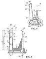
- the passage 53 along the first section 70 has an internal taper of between 1.5° and 5° and the second section 72 extends along a curve such that the distal end 54E is generally parallel to the longitudinal axis 8 (as best shown in Figure 4 ).
- the internal wall defining the passage 53 along the first section 70 extends along a line that defines an angle ⁇ 2 with a horizontal line.
- the angle ⁇ 2 may range between 85° and 88.5°.
- the passage 53 along the section 72 may also have a tapering shape and the passage 53 may also have a greater internal taper than the passage 53 along the second section 72.
- the passage 53 along the second section 72 may have an internal taper of between 0.01° and 1.5° and its internal wall, when seen in Figure 6 , may extend along a line that defines an angle ⁇ 3 with a horizontal line.
- the angle ⁇ 3 may range between 89.99° and 88.5°. It is understood that as long as the angle ⁇ 3 is less than 90°, the passage 53 along the second section 72 has an internal taper.
- the diameter of the passage 53 of the tube 22 may reduce gradually from the first end portion 52 to the second end portion 54. More specifically, the passage 53 has a first diameter d 1 at the first end portion 52 of the first section 70 and the passage 53 has a second diameter d 2 at the second end portion 54 of the second section 72 where there is a ratio between the second diameter d 2 and the first diameter d 1 of between 0.55 and 0.75 as a result of the internal tapering of the first and second sections 70, 72.
- the passage 53 also has an intermediate (third) diameter d 3 at the entry of the second section 72 where the ratio between third diameter d 3 and the first diameter d 1 is between 0.6 and 0.75 and the ratio between the second diameter d 2 and the third diameter d 3 is between 0.91 and 0.99.
- the first diameter d 1 at the entry of the second section 70 may be between 0.724 cm (0.285 inches) and 0.749 cm (0.295 inches) (advantageously around 0.736 cm (0.290 inches)
- the third (intermediate) diameter d 3 at the entry to the second section 72 may be between 0.495 cm (0.195 inches) and 0.520 cm (0.205 inches) (advantageously around 0.508 cm (0.200 inches)
- the second diameter d 2 at the exit of the second section 72 (distal end 54E) may be between of 0.470 cm (0.185 inches) and 0.495 cm (0.195 inches) (advantageously around 0.483 cm (0.190 inches)).
- the diameter of the passage 53 of the tube 22 may reduce by 60% to 85% between the first end portion 52 and the second end portion 54.
- the internal member 20 is removable from the cap 12, such that it can be taken out of the cap 12 to be cleaned or replaced.
- the internal member 20 can be made of an elastomeric material, such as food grade silicone, among other possible materials.
- the internal member 20 comprises the tube 22 having the first end portion 52, the second end portion 54 and the passage 53 for pouring the food dressing out of the second end portion 54 that is open to the atmosphere.
- the internal member 20 further comprises an aeration tube 24 for enabling air from the atmosphere to enter the internal space 18.
- the aeration tube 24 comprises a first end 60 defining a first opening 62 facing the internal space 18 of the container 14 and a second end 64 defining a second opening 66 facing the internal space 50 of the external shell of the cap 12.
- the aeration tube 24 thus defines an air passage 67 between the internal space 18 of the container and the internal space 50 of the external shell that, in use, when food dressing is dispensed through the passage 53 of the tube 22, allows air to penetrate into the internal space 18 of the container 14 in order to replace the volume of food dressing being dispensed out.
- food dressing can dispense out through the passage 53 of the tube 22 smoothly, without the risk of bubbles interrupting the flow.
- the internal member 20 further comprises a central wall portion 56 and an outer rim 58.
- the central wall portion 56 forms a type of cap and the outer rim 58 is pressed against the shoulder 40 when the cap 12 is attached to the container 14 for preventing the food dressing within the internal space 18.
- an internal peripheral shoulder 53 of the cap 12 press against the outer rim 58 that is pushed against the upper surface of the shoulder 40 such that the outer rim 58 sealingly engages with the shoulder 40 in order to create a seal between the member 20 and the peripheral ring 38 such that food dressing can only flow through the opening 27 of the container 14, the opening 29 of the peripheral ring 38, enter in the passage 53 of the tube 22, flow in the passage 53 and exit the tube 22 at the upper end portion 54 (through the spout 16) when the dispenser 10 is tilted.
- the dispenser also has a sealing member 42 in order to create a seal between the peripheral ring 38 and the container 14.
- the sealing member 42 and the pressing of the outer rim 58 against the shoulder 40 therefore prevent the food dressing from leaking between the container 14 and the peripheral ring 38 and between the peripheral ring 38 and the internal member 20.
- the outer rim 58 of the internal member 20 would be pressed on the upper surface of the rim 26 of the container 14 so as to sealingly engage the rim 26 in order to create a seal between the internal member 20 and the container 14.
- the distal end 54E of the second end portion 54 has an angle ⁇ 1 of between approximately 40° and 50°, and preferably 45°, such that the distal end 54E is generally parallel to the longitudinal axis 8 when the distal end 54E is mounted around the proximal end 19 of the spout 16.
- the portion of the second end portion 54 that engages the spout 16 and the spout 16 both extend along a line defining an angle ⁇ 4 of approximately 40° to 50° about the a line parallel to the longitudinal axis 8.
- the second end portion 54 may engage with the spout 16 by being placed around the proximal end 19 of the spout 16, or by being placed within the passage of the spout 16.
- the engagement between the spout 16 and the second end portion 54 of the tube is generally created via a friction fit.
- the dispenser 10 has been tilted downwardly in a direction indicated by arrow 80 into a pouring position.
- the food dressing that is stored within the internal space 18 can be pour from the internal space 18, flow through the openings 27, 39, flow through the passage 53 along the first and second sections 70, 72 of the tube 22 and is poured out of the second end portion 54 (or spout 16 when a spout is located within the second end portion 54).
- the dispenser 10 is tilted in substantially the reverse direction indicated by arrows 82, in order to move the dispenser 10 back into an upright position.
- the flow of the food dressing from the second end portion 54 (spout 16) is interrupted (as depicted in Figure 8 ) and the food dressing starts to flow back through the passage 53 into the internal space 18.
- the dispenser 10 As depicted in Figures 9 and 10 , as the dispenser 10 is moved back into the upright position, the food dressing contained in the passage 53 does not drip down out of the second end portion (spout 16) or leave a trail running down the outside surface of the cap 12. Instead, there is a relatively clean interruption of the flow of food dressing that is poured out of the second end portion 54 (spout 16), such that the remaining food dressing is drawn back into the internal space 18. As a result, the dispenser 10 is a substantially drip-free pouring dispenser.
- the fluid, the food dressing in this case, that flows within the narrower, more constricted area of the tube passage flows at a higher velocity and a lower pressure than the fluid that flows within the wider, less constricted area of the tube passage.
- the tapering shape of the passage 53 along the first section 70 of the tube 22 creates a type of venturi tube effect at the entry of the second section 72 when the food dressing is poured out.
- the area of the passage 53 near the entry of the second section 72 is therefore at a lower pressure.
- the tube 22 has a passage 53 with a first internal taper along the first section 70 and a second internal taper along the second section 72, it is believed that a tube with a curved distal end portion with a end face parallel to the longitudinal axis of the dispenser and a passage with an internal taper along the length of the tube would create forces on the food dressing causing the food dressing remaining in the passage to flow back into the internal space of the container without dripping from the distal end portion when the dispenser is moved back by the user into an upright position.
- Food dressings such as olive oil have relatively long chains of carbon molecules, which create relatively strong intermolecular forces.
- Many food dressings further comprise high viscosities. For example, the viscosity of olive oil is in the order of 84 cPoise.
- the strong intermolecular forces, together with the narrowing of the internal diameter of the passage 53 of the tube 22 may further help to draw the food dressing remaining in the passage 53 back into the internal space 18 of the container 14 once the pouring of the food dressing is complete and the user moves back the dispenser 10 into the upright position.
- the second section 72 extends along a curve such that the distal end 54E is generally parallel to the longitudinal axis 8, and because of the capillary action between the food dressing and the internal wall of the passage 53 of the tube 22, which is made of food grade silicone, the food dressing is caused to be pulled back into the tube 22, as opposed to dripping out of the second end portion 54 (spout 16). Also, when the user stops pouring and moves back the dispenser 10 into the upright position, air bubbles can be present in the food dressing at the upper surface of the internal wall of the passage 53 along the second section 72 and these air bubbles may facilitate to draw the food dressing back into the internal space 18 of the container 14.
- these air bubbles and this separation of the food dressing in several drops may facilitate to draw of any remaining drops in the passage 53 at the second section 72 back into the internal space 18 of the container 14.
Landscapes
- Engineering & Computer Science (AREA)
- Mechanical Engineering (AREA)
- Closures For Containers (AREA)
- Table Devices Or Equipment (AREA)
Claims (14)
- Distributeur (10) pour sauce alimentaire, ledit distributeur s'étendant le long d'un axe longitudinal (8) et comprenant :(a) un contenant (14) définissant un espace interne (18) permettant de recevoir un volume de la sauce alimentaire, ledit contenant ayant un rebord (26) définissant une ouverture (27) ; et(b) un bouchon (12) ayant une coque externe et un organe interne (20), dans lequel ladite coque externe comprend : une paroi périphérique (46) et une paroi de dessus (48) définissant un espace interne (50), et une portion d'attache (34) permettant d'attacher ledit bouchon audit contenant pour au moins couvrir partiellement ladite ouverture dudit rebord, et dans lequel ledit organe interne (20) comporte un tube (22) s'étendant entre une première portion d'extrémité (52) ayant une première ouverture (520) en regard dudit espace interne dudit contenant et une seconde portion d'extrémité (54) ayant une extrémité distale (54E) avec une seconde ouverture (540) en regard de l'atmosphère de telle sorte que ledit tube définisse un passage (53) entre lesdites première et seconde ouvertures (520, 540) pour permettre une communication fluidique entre ledit espace interne dudit contenant et l'atmosphère, dans lequel ledit tube (22) a une première section (70) s'étendant depuis ladite première portion d'extrémité (52) et une seconde section (72) se terminant à ladite extrémité distale (54E), dans lequel ledit passage (53) a un premier effilement interne le long de ladite première section (70) et ladite seconde section (72) s'étend le long d'une courbe de telle sorte que ladite extrémité distale (54E) est généralement parallèle audit axe longitudinal (8) ; ledit distributeur étant caractérisé en ce que ladite coque externe comprend en outre un bec (16) monté au moins partiellement dans une ouverture (47) ménagée sur ladite paroi périphérique de ladite coque externe, ledit tube (22) est constitué d'un matériau élastomère, et ladite seconde portion d'extrémité (54) dudit tube est montée autour d'une extrémité proximale (19) dudit bec (16), et dans lequel, en utilisation, lorsque ledit distributeur est incliné par un utilisateur, la sauce alimentaire s'écoule au sein dudit passage (53) et est versée de ladite seconde portion d'extrémité (54) dudit tube et à travers ledit bec (16), et lorsque le distributeur est remis en position droite par l'utilisateur, la sauce alimentaire restant dans ledit passage (53) s'écoule de retour dans ledit espace interne dudit contenant sans goutter depuis ledit bec (16).
- Distributeur selon la revendication 1, dans lequel ledit premier effilement interne est entre 1,5° et 5° et ledit passage (53) a un second effilement interne entre 0,01° et 1,5° le long de ladite seconde section (72).
- Distributeur selon la revendication 1 ou 2, dans lequel ladite première section (70) a une plus grande longueur que ladite seconde section (72).
- Distributeur selon la revendication 3, dans lequel ledit passage (53) a un premier diamètre au niveau de ladite première portion d'extrémité (52) et un second diamètre au niveau de ladite seconde portion d'extrémité (54) où un rapport entre ledit second diamètre et ledit premier diamètre est entre 0,55 et 0,75.
- Distributeur selon la revendication 4, dans lequel ledit passage (53) a un diamètre intermédiaire au niveau d'une entrée de ladite seconde section (72) où un rapport entre ledit diamètre intermédiaire et ledit premier diamètre est entre 0,6 et 0,75 et un rapport entre ledit second diamètre et ledit diamètre intermédiaire est entre 0,91 et 0,99.
- Distributeur selon la revendication 5, dans lequel ledit premier diamètre est entre 0,724 cm (0,285 pouce) et 0,749 cm (0,295 pouce), ledit diamètre intermédiaire est entre 0,495 cm (0,195 pouce) et 0,520 cm (0,205 pouce) et ledit second diamètre est entre 0,470 cm (0,185 pouce) et 0,495 cm (0,195 pouce).
- Distributeur selon la revendication 3, dans lequel ladite première section (70) forme entre 55 % et 70 % de ladite longueur dudit tube et ladite seconde section forme entre 30 % et 45 % de ladite longueur dudit tube.
- Distributeur selon la revendication 3, dans lequel ladite première section (70) a une première longueur entre 2,79 cm (1,10 pouce) et 3,30 cm (1,30 pouce) et ladite seconde section (72) a une seconde longueur entre 1,65 cm (0,65 pouce) et 2,16 cm (0,85 pouce).
- Distributeur selon l'une quelconque des revendications 1 à 8, dans lequel ledit matériau élastomère est du silicone de qualité alimentaire et dans lequel ledit organe interne (20) et ledit tube (22) sont constitués de silicone de qualité alimentaire.
- Distributeur selon l'une quelconque des revendications 1 à 9, dans lequel ledit bec est constitué d'aluminium, de plastique ou d'acier inoxydable.
- Distributeur selon l'une quelconque des revendications 1 à 10, dans lequel ledit organe interne (20) comprend un tube d'aération (24) ayant une première extrémité (60) avec une première ouverture (62) en regard dudit espace interne (18) dudit contenant et une seconde extrémité (64) avec une seconde ouverture (66) en regard dudit espace interne (50) de ladite coque externe de telle sorte que ledit tube d'aération définisse un passage d'air entre ledit espace interne (18) dudit contenant et ledit espace interne (50) de ladite coque externe.
- Distributeur selon la revendication 11, dans lequel ledit organe interne (20) a un rebord externe (58) qui se met en prise de manière étanche avec ledit rebord (26) dudit contenant et dans lequel, lorsque ledit distributeur est incliné, la sauce alimentaire s'écoule au sein dudit passage (53) et est versée de ladite seconde portion d'extrémité (54) dudit tube pendant que l'air peut également pénétrer dans ledit espace interne (18) dudit contenant via ledit passage d'air (67).
- Distributeur selon la revendication 12, dans lequel ledit distributeur comprend en outre une bague périphérique (38) ayant un épaulement (40) qui se met en prise de manière étanche avec ledit rebord (26) dudit contenant, et dans lequel ledit organe interne (20) a un rebord externe (58) qui se met en prise de manière étanche avec ledit épaulement (40) de ladite bague périphérique (38) et dans lequel, lorsque ledit distributeur est incliné, la sauce alimentaire s'écoule au sein dudit passage (53) et est versée de ladite seconde portion d'extrémité (54) dudit tube alors que l'air peut également pénétrer dans ledit espace interne dudit contenant via ledit passage d'air (67).
- Distributeur selon l'une quelconque des revendications 1 à 13, dans lequel ledit contenant (14) est constitué de plastique ou verre transparent.
Applications Claiming Priority (1)
| Application Number | Priority Date | Filing Date | Title |
|---|---|---|---|
| US30861410P | 2010-02-26 | 2010-02-26 |
Publications (2)
| Publication Number | Publication Date |
|---|---|
| EP2361845A1 EP2361845A1 (fr) | 2011-08-31 |
| EP2361845B1 true EP2361845B1 (fr) | 2014-05-07 |
Family
ID=43929083
Family Applications (2)
| Application Number | Title | Priority Date | Filing Date |
|---|---|---|---|
| EP20110155853 Not-in-force EP2361848B1 (fr) | 2010-02-26 | 2011-02-24 | Distributeur d'huile et de vinaigre. |
| EP20110156101 Not-in-force EP2361845B1 (fr) | 2010-02-26 | 2011-02-25 | Distributeur pour vinaigrette |
Family Applications Before (1)
| Application Number | Title | Priority Date | Filing Date |
|---|---|---|---|
| EP20110155853 Not-in-force EP2361848B1 (fr) | 2010-02-26 | 2011-02-24 | Distributeur d'huile et de vinaigre. |
Country Status (3)
| Country | Link |
|---|---|
| US (2) | US8690015B2 (fr) |
| EP (2) | EP2361848B1 (fr) |
| CA (2) | CA2732363A1 (fr) |
Cited By (1)
| Publication number | Priority date | Publication date | Assignee | Title |
|---|---|---|---|---|
| DE102017200772A1 (de) * | 2017-01-18 | 2018-07-19 | Wmf Group Gmbh | Isolierkannendeckel und Verwendungen hiervon |
Families Citing this family (13)
| Publication number | Priority date | Publication date | Assignee | Title |
|---|---|---|---|---|
| USD673448S1 (en) * | 2011-03-04 | 2013-01-01 | S. C. Johnson & Son, Inc. | Container shroud |
| GB2497781B (en) | 2011-12-20 | 2014-02-12 | Ben Tagoe | Liquid pourer |
| RU2494944C1 (ru) * | 2012-06-21 | 2013-10-10 | Антон Аркадьевич Шапиро | Устройство для приготовления топливной смеси для двигателей внутреннего сгорания |
| FR3019532B1 (fr) * | 2014-04-08 | 2017-10-06 | Qualipac Sa | Flacon, systeme comprenant un tel flacon et leur procede de fabrication. |
| USD763086S1 (en) * | 2014-09-18 | 2016-08-09 | Prestone Products Corporation | Coolant additive package |
| US10617244B1 (en) * | 2015-04-16 | 2020-04-14 | Aron J. LANTZ | Easymeal food and drink dispensing device |
| US10172486B2 (en) | 2015-06-01 | 2019-01-08 | Double Take Containers, Llc | Multi-chambered shot container |
| CN104958019B (zh) * | 2015-06-25 | 2017-11-10 | 南安泛科轴承检测技术有限公司 | 可调配液体的调味瓶 |
| ES2595243B1 (es) * | 2016-09-16 | 2017-04-06 | Caviaroli, S.L. | Procedimiento de envasado de capsulas alimenticias y producto alimenticio envasado obtenido mediante el mismo |
| WO2019075442A1 (fr) * | 2017-10-13 | 2019-04-18 | The Pure Pour Llc | Système et dispositif de couplage pour verser |
| USD878002S1 (en) * | 2017-10-31 | 2020-03-10 | Sky Urns, Inc. | Pet Urn |
| US10849445B2 (en) | 2018-05-01 | 2020-12-01 | Upslope Brands, Inc. | Beverage container |
| EP4594207A1 (fr) * | 2022-09-29 | 2025-08-06 | Grabher, Rene | Tête de récipient |
Family Cites Families (33)
| Publication number | Priority date | Publication date | Assignee | Title |
|---|---|---|---|---|
| US1436708A (en) * | 1922-04-03 | 1922-11-28 | John H Goebel | Pouring nozzle for bottles |
| US1509360A (en) * | 1924-02-14 | 1924-09-23 | David D Lewis | Dispensing can |
| US2099292A (en) * | 1936-08-25 | 1937-11-16 | Mortimer J Brown | Dripless dispensing device |
| US2197995A (en) * | 1937-04-06 | 1940-04-23 | Dill Mfg Co | Valve |
| GB587994A (en) * | 1945-01-01 | 1947-05-12 | Harry Milman Bickle | Improvements relating to stoppers for bottles and other containers |
| US2780391A (en) * | 1952-09-24 | 1957-02-05 | Baker Chem Co J T | Spout comprising a large outlet passage and a smaller outlet passage located therein |
| US2727644A (en) * | 1953-07-02 | 1955-12-20 | Theodore A Giannos | Pouring cap |
| US2808182A (en) * | 1954-11-15 | 1957-10-01 | Leonard Altman | Pouring stopper |
| US2825495A (en) * | 1955-03-18 | 1958-03-04 | Fazio Angelo | Screw top liquor dispenser for bottles |
| GB978453A (en) * | 1962-10-05 | 1964-12-23 | Schenley Ind Inc | An improved container closure and pouring device |
| US3347420A (en) * | 1965-08-16 | 1967-10-17 | Robert J Donoghue | Multi-compartment container for dispensing measured quantities of a plurality of liquids |
| US3386626A (en) * | 1967-02-09 | 1968-06-04 | Kearney Patrick | Non-refillable bottle and pourer |
| US3613955A (en) * | 1969-07-15 | 1971-10-19 | Monsanto Co | Compartmentalized container package |
| DE3208666A1 (de) * | 1982-03-10 | 1983-09-22 | Siemens AG, 1000 Berlin und 8000 München | Zahnaerztliches spritzhandstueck |
| DE3514133C2 (de) * | 1985-04-19 | 1994-07-28 | Wella Ag | Mehrkammerbehälter |
| US4596341A (en) * | 1985-09-18 | 1986-06-24 | The Coca-Cola Company | Toy drinking cup |
| DE3731242A1 (de) * | 1987-09-17 | 1989-03-30 | Joka Kathetertechnik Gmbh | Absperrvorrichtung an einer fluessigkeitsentnahme- oder infusionseinrichtung |
| GB8727678D0 (en) * | 1987-11-26 | 1987-12-31 | Goodall D T | Pouring device |
| DE3816859A1 (de) * | 1988-05-18 | 1989-11-23 | Henkel Kgaa | Mehrkomponentenbehaeltnis |
| US5062550A (en) * | 1990-05-24 | 1991-11-05 | Singh Bharat H | Selective flow dispensing container |
| US5511700A (en) * | 1994-07-18 | 1996-04-30 | Ouno; Taiichi | Table pot for liquid seasoning |
| US5931356A (en) * | 1997-06-27 | 1999-08-03 | Dart Industries Inc. | Dispenser for oil/vinegar bottle |
| FR2775956B1 (fr) * | 1998-03-16 | 2000-06-02 | John Genthon | Antigoutte a liquide a fixation exterieur |
| DE19917622C2 (de) * | 1999-04-19 | 2001-05-17 | Ferton Holding Sa | Quetschventil |
| US6398077B1 (en) * | 2000-02-11 | 2002-06-04 | Seaquist Closures Foreign, Inc. | Package with multiple chambers and valves |
| US7731062B2 (en) * | 2000-09-22 | 2010-06-08 | Gebauer Company | Apparatus and method for dispensing liquids |
| US7334705B2 (en) * | 2001-02-26 | 2008-02-26 | Kao Corporation | Container |
| CH698173B1 (de) * | 2005-11-08 | 2009-06-15 | Belcap Switzerland Ag | Behälter-Verschluss zum gleichzeitigen Ausgiessen zweier separater Flüssigkeiten in einem bestimmten Mengenverhältnis. |
| US7464834B2 (en) * | 2006-02-27 | 2008-12-16 | Rieke Corporation | Dispensing container for two flowable products |
| CN101622180B (zh) * | 2006-09-22 | 2011-12-07 | 尼科塔股份有限公司 | 流体分配器及分配流体的方法 |
| US7665631B2 (en) * | 2006-11-29 | 2010-02-23 | Dan Pikowski | Double chamber variable condiment dispenser bottle |
| US20080277419A1 (en) * | 2006-12-21 | 2008-11-13 | Chef'n Corporation | Fluid Dispenser |
| US7594589B2 (en) * | 2007-06-14 | 2009-09-29 | Owens-Brockway Glass Container Inc. | Dual-container package and a dispensing closure for such package |
-
2011
- 2011-02-22 CA CA 2732363 patent/CA2732363A1/fr not_active Abandoned
- 2011-02-24 EP EP20110155853 patent/EP2361848B1/fr not_active Not-in-force
- 2011-02-25 US US13/034,742 patent/US8690015B2/en not_active Expired - Fee Related
- 2011-02-25 CA CA 2732815 patent/CA2732815A1/fr not_active Abandoned
- 2011-02-25 EP EP20110156101 patent/EP2361845B1/fr not_active Not-in-force
- 2011-02-25 US US13/035,333 patent/US8827123B2/en not_active Expired - Fee Related
Cited By (1)
| Publication number | Priority date | Publication date | Assignee | Title |
|---|---|---|---|---|
| DE102017200772A1 (de) * | 2017-01-18 | 2018-07-19 | Wmf Group Gmbh | Isolierkannendeckel und Verwendungen hiervon |
Also Published As
| Publication number | Publication date |
|---|---|
| CA2732363A1 (fr) | 2011-08-26 |
| EP2361848A1 (fr) | 2011-08-31 |
| EP2361845A1 (fr) | 2011-08-31 |
| US8690015B2 (en) | 2014-04-08 |
| EP2361848B1 (fr) | 2012-09-19 |
| US8827123B2 (en) | 2014-09-09 |
| US20120048896A1 (en) | 2012-03-01 |
| US20110253745A1 (en) | 2011-10-20 |
| CA2732815A1 (fr) | 2011-08-26 |
Similar Documents
| Publication | Publication Date | Title |
|---|---|---|
| US8827123B2 (en) | Dispenser for food dressing | |
| US9187219B2 (en) | Pour lip closure with drain back | |
| US8011540B1 (en) | Aerator bottle pourer | |
| EP2091859B1 (fr) | Bouchon verseur anti-goutte | |
| US6688501B2 (en) | Dispensing closure for spreadable product | |
| US7568576B2 (en) | Infusion cap | |
| US8365960B1 (en) | Multi-compartment beverage container | |
| US4804119A (en) | Liquid dispenser | |
| CA2954930C (fr) | Bouchon verseur pour le manchon d'un jerrican ou d'un recipient quelconque pour le versement controle vers plusieurs cotes | |
| US20110233236A1 (en) | Continuous, complete, automatic, non-leaking, non-aerating, positive pressure one-piece vent and pouring combination utilizing one direct venting aperture | |
| US20080230573A1 (en) | Vessel | |
| US20190315532A1 (en) | Pour spout | |
| US5320260A (en) | Syrup dispenser | |
| US20160037975A1 (en) | Multi-Fit, Fast Connect, Dispenser to Bottle 8 Connection Kit for Liquid Dispensers | |
| EP3535197B1 (fr) | Bouteille à écoulement régulé | |
| US5839625A (en) | Extruded fluted insert dispensing tube | |
| US20140144547A1 (en) | Jar buddy | |
| JPS6219559Y2 (fr) | ||
| US7000804B2 (en) | Container dispenser device for separated flowable contents | |
| US20130161362A1 (en) | Neck Extender Device | |
| WO2013005181A1 (fr) | Récipient de distribution et buse permettant de distribuer un liquide contenant de l'huile de consommation | |
| JP2004010054A (ja) | 液体収納容器の注出栓 | |
| AU2017202530A1 (en) | Drink pouring dispenser | |
| AU2005209696A1 (en) | Pouring Aid |
Legal Events
| Date | Code | Title | Description |
|---|---|---|---|
| PUAI | Public reference made under article 153(3) epc to a published international application that has entered the european phase |
Free format text: ORIGINAL CODE: 0009012 |
|
| AK | Designated contracting states |
Kind code of ref document: A1 Designated state(s): AL AT BE BG CH CY CZ DE DK EE ES FI FR GB GR HR HU IE IS IT LI LT LU LV MC MK MT NL NO PL PT RO RS SE SI SK SM TR |
|
| AX | Request for extension of the european patent |
Extension state: BA ME |
|
| 17P | Request for examination filed |
Effective date: 20120227 |
|
| 17Q | First examination report despatched |
Effective date: 20130816 |
|
| GRAP | Despatch of communication of intention to grant a patent |
Free format text: ORIGINAL CODE: EPIDOSNIGR1 |
|
| INTG | Intention to grant announced |
Effective date: 20131220 |
|
| GRAS | Grant fee paid |
Free format text: ORIGINAL CODE: EPIDOSNIGR3 |
|
| GRAA | (expected) grant |
Free format text: ORIGINAL CODE: 0009210 |
|
| AK | Designated contracting states |
Kind code of ref document: B1 Designated state(s): AL AT BE BG CH CY CZ DE DK EE ES FI FR GB GR HR HU IE IS IT LI LT LU LV MC MK MT NL NO PL PT RO RS SE SI SK SM TR |
|
| REG | Reference to a national code |
Ref country code: GB Ref legal event code: FG4D |
|
| REG | Reference to a national code |
Ref country code: AT Ref legal event code: REF Ref document number: 666452 Country of ref document: AT Kind code of ref document: T Effective date: 20140515 |
|
| REG | Reference to a national code |
Ref country code: IE Ref legal event code: FG4D |
|
| REG | Reference to a national code |
Ref country code: DE Ref legal event code: R096 Ref document number: 602011006662 Country of ref document: DE Effective date: 20140626 |
|
| REG | Reference to a national code |
Ref country code: AT Ref legal event code: MK05 Ref document number: 666452 Country of ref document: AT Kind code of ref document: T Effective date: 20140507 |
|
| REG | Reference to a national code |
Ref country code: NL Ref legal event code: VDEP Effective date: 20140507 |
|
| REG | Reference to a national code |
Ref country code: LT Ref legal event code: MG4D |
|
| PG25 | Lapsed in a contracting state [announced via postgrant information from national office to epo] |
Ref country code: GR Free format text: LAPSE BECAUSE OF FAILURE TO SUBMIT A TRANSLATION OF THE DESCRIPTION OR TO PAY THE FEE WITHIN THE PRESCRIBED TIME-LIMIT Effective date: 20140808 Ref country code: IS Free format text: LAPSE BECAUSE OF FAILURE TO SUBMIT A TRANSLATION OF THE DESCRIPTION OR TO PAY THE FEE WITHIN THE PRESCRIBED TIME-LIMIT Effective date: 20140907 Ref country code: LT Free format text: LAPSE BECAUSE OF FAILURE TO SUBMIT A TRANSLATION OF THE DESCRIPTION OR TO PAY THE FEE WITHIN THE PRESCRIBED TIME-LIMIT Effective date: 20140507 Ref country code: CY Free format text: LAPSE BECAUSE OF FAILURE TO SUBMIT A TRANSLATION OF THE DESCRIPTION OR TO PAY THE FEE WITHIN THE PRESCRIBED TIME-LIMIT Effective date: 20140507 Ref country code: NO Free format text: LAPSE BECAUSE OF FAILURE TO SUBMIT A TRANSLATION OF THE DESCRIPTION OR TO PAY THE FEE WITHIN THE PRESCRIBED TIME-LIMIT Effective date: 20140807 Ref country code: FI Free format text: LAPSE BECAUSE OF FAILURE TO SUBMIT A TRANSLATION OF THE DESCRIPTION OR TO PAY THE FEE WITHIN THE PRESCRIBED TIME-LIMIT Effective date: 20140507 |
|
| PG25 | Lapsed in a contracting state [announced via postgrant information from national office to epo] |
Ref country code: SE Free format text: LAPSE BECAUSE OF FAILURE TO SUBMIT A TRANSLATION OF THE DESCRIPTION OR TO PAY THE FEE WITHIN THE PRESCRIBED TIME-LIMIT Effective date: 20140507 Ref country code: ES Free format text: LAPSE BECAUSE OF FAILURE TO SUBMIT A TRANSLATION OF THE DESCRIPTION OR TO PAY THE FEE WITHIN THE PRESCRIBED TIME-LIMIT Effective date: 20140507 Ref country code: RS Free format text: LAPSE BECAUSE OF FAILURE TO SUBMIT A TRANSLATION OF THE DESCRIPTION OR TO PAY THE FEE WITHIN THE PRESCRIBED TIME-LIMIT Effective date: 20140507 Ref country code: LV Free format text: LAPSE BECAUSE OF FAILURE TO SUBMIT A TRANSLATION OF THE DESCRIPTION OR TO PAY THE FEE WITHIN THE PRESCRIBED TIME-LIMIT Effective date: 20140507 Ref country code: HR Free format text: LAPSE BECAUSE OF FAILURE TO SUBMIT A TRANSLATION OF THE DESCRIPTION OR TO PAY THE FEE WITHIN THE PRESCRIBED TIME-LIMIT Effective date: 20140507 Ref country code: AT Free format text: LAPSE BECAUSE OF FAILURE TO SUBMIT A TRANSLATION OF THE DESCRIPTION OR TO PAY THE FEE WITHIN THE PRESCRIBED TIME-LIMIT Effective date: 20140507 Ref country code: PL Free format text: LAPSE BECAUSE OF FAILURE TO SUBMIT A TRANSLATION OF THE DESCRIPTION OR TO PAY THE FEE WITHIN THE PRESCRIBED TIME-LIMIT Effective date: 20140507 |
|
| PG25 | Lapsed in a contracting state [announced via postgrant information from national office to epo] |
Ref country code: PT Free format text: LAPSE BECAUSE OF FAILURE TO SUBMIT A TRANSLATION OF THE DESCRIPTION OR TO PAY THE FEE WITHIN THE PRESCRIBED TIME-LIMIT Effective date: 20140908 |
|
| PG25 | Lapsed in a contracting state [announced via postgrant information from national office to epo] |
Ref country code: SK Free format text: LAPSE BECAUSE OF FAILURE TO SUBMIT A TRANSLATION OF THE DESCRIPTION OR TO PAY THE FEE WITHIN THE PRESCRIBED TIME-LIMIT Effective date: 20140507 Ref country code: BE Free format text: LAPSE BECAUSE OF FAILURE TO SUBMIT A TRANSLATION OF THE DESCRIPTION OR TO PAY THE FEE WITHIN THE PRESCRIBED TIME-LIMIT Effective date: 20140507 Ref country code: EE Free format text: LAPSE BECAUSE OF FAILURE TO SUBMIT A TRANSLATION OF THE DESCRIPTION OR TO PAY THE FEE WITHIN THE PRESCRIBED TIME-LIMIT Effective date: 20140507 Ref country code: DK Free format text: LAPSE BECAUSE OF FAILURE TO SUBMIT A TRANSLATION OF THE DESCRIPTION OR TO PAY THE FEE WITHIN THE PRESCRIBED TIME-LIMIT Effective date: 20140507 Ref country code: CZ Free format text: LAPSE BECAUSE OF FAILURE TO SUBMIT A TRANSLATION OF THE DESCRIPTION OR TO PAY THE FEE WITHIN THE PRESCRIBED TIME-LIMIT Effective date: 20140507 Ref country code: RO Free format text: LAPSE BECAUSE OF FAILURE TO SUBMIT A TRANSLATION OF THE DESCRIPTION OR TO PAY THE FEE WITHIN THE PRESCRIBED TIME-LIMIT Effective date: 20140507 |
|
| REG | Reference to a national code |
Ref country code: DE Ref legal event code: R097 Ref document number: 602011006662 Country of ref document: DE |
|
| PG25 | Lapsed in a contracting state [announced via postgrant information from national office to epo] |
Ref country code: NL Free format text: LAPSE BECAUSE OF FAILURE TO SUBMIT A TRANSLATION OF THE DESCRIPTION OR TO PAY THE FEE WITHIN THE PRESCRIBED TIME-LIMIT Effective date: 20140507 |
|
| PLBE | No opposition filed within time limit |
Free format text: ORIGINAL CODE: 0009261 |
|
| STAA | Information on the status of an ep patent application or granted ep patent |
Free format text: STATUS: NO OPPOSITION FILED WITHIN TIME LIMIT |
|
| 26N | No opposition filed |
Effective date: 20150210 |
|
| PG25 | Lapsed in a contracting state [announced via postgrant information from national office to epo] |
Ref country code: IT Free format text: LAPSE BECAUSE OF FAILURE TO SUBMIT A TRANSLATION OF THE DESCRIPTION OR TO PAY THE FEE WITHIN THE PRESCRIBED TIME-LIMIT Effective date: 20140507 |
|
| REG | Reference to a national code |
Ref country code: DE Ref legal event code: R097 Ref document number: 602011006662 Country of ref document: DE Effective date: 20150210 |
|
| PG25 | Lapsed in a contracting state [announced via postgrant information from national office to epo] |
Ref country code: SI Free format text: LAPSE BECAUSE OF FAILURE TO SUBMIT A TRANSLATION OF THE DESCRIPTION OR TO PAY THE FEE WITHIN THE PRESCRIBED TIME-LIMIT Effective date: 20140507 |
|
| PG25 | Lapsed in a contracting state [announced via postgrant information from national office to epo] |
Ref country code: LU Free format text: LAPSE BECAUSE OF FAILURE TO SUBMIT A TRANSLATION OF THE DESCRIPTION OR TO PAY THE FEE WITHIN THE PRESCRIBED TIME-LIMIT Effective date: 20150225 |
|
| REG | Reference to a national code |
Ref country code: CH Ref legal event code: PL |
|
| PG25 | Lapsed in a contracting state [announced via postgrant information from national office to epo] |
Ref country code: LI Free format text: LAPSE BECAUSE OF NON-PAYMENT OF DUE FEES Effective date: 20150228 Ref country code: CH Free format text: LAPSE BECAUSE OF NON-PAYMENT OF DUE FEES Effective date: 20150228 Ref country code: MC Free format text: LAPSE BECAUSE OF FAILURE TO SUBMIT A TRANSLATION OF THE DESCRIPTION OR TO PAY THE FEE WITHIN THE PRESCRIBED TIME-LIMIT Effective date: 20140507 |
|
| REG | Reference to a national code |
Ref country code: IE Ref legal event code: MM4A |
|
| PG25 | Lapsed in a contracting state [announced via postgrant information from national office to epo] |
Ref country code: IE Free format text: LAPSE BECAUSE OF NON-PAYMENT OF DUE FEES Effective date: 20150225 |
|
| REG | Reference to a national code |
Ref country code: FR Ref legal event code: PLFP Year of fee payment: 6 |
|
| PGFP | Annual fee paid to national office [announced via postgrant information from national office to epo] |
Ref country code: DE Payment date: 20160218 Year of fee payment: 6 |
|
| PGFP | Annual fee paid to national office [announced via postgrant information from national office to epo] |
Ref country code: GB Payment date: 20160215 Year of fee payment: 6 |
|
| PG25 | Lapsed in a contracting state [announced via postgrant information from national office to epo] |
Ref country code: MT Free format text: LAPSE BECAUSE OF FAILURE TO SUBMIT A TRANSLATION OF THE DESCRIPTION OR TO PAY THE FEE WITHIN THE PRESCRIBED TIME-LIMIT Effective date: 20140507 |
|
| REG | Reference to a national code |
Ref country code: FR Ref legal event code: PLFP Year of fee payment: 7 |
|
| PG25 | Lapsed in a contracting state [announced via postgrant information from national office to epo] |
Ref country code: HU Free format text: LAPSE BECAUSE OF FAILURE TO SUBMIT A TRANSLATION OF THE DESCRIPTION OR TO PAY THE FEE WITHIN THE PRESCRIBED TIME-LIMIT; INVALID AB INITIO Effective date: 20110225 Ref country code: BG Free format text: LAPSE BECAUSE OF FAILURE TO SUBMIT A TRANSLATION OF THE DESCRIPTION OR TO PAY THE FEE WITHIN THE PRESCRIBED TIME-LIMIT Effective date: 20140507 Ref country code: SM Free format text: LAPSE BECAUSE OF FAILURE TO SUBMIT A TRANSLATION OF THE DESCRIPTION OR TO PAY THE FEE WITHIN THE PRESCRIBED TIME-LIMIT Effective date: 20140507 |
|
| PG25 | Lapsed in a contracting state [announced via postgrant information from national office to epo] |
Ref country code: TR Free format text: LAPSE BECAUSE OF FAILURE TO SUBMIT A TRANSLATION OF THE DESCRIPTION OR TO PAY THE FEE WITHIN THE PRESCRIBED TIME-LIMIT Effective date: 20140507 |
|
| REG | Reference to a national code |
Ref country code: DE Ref legal event code: R119 Ref document number: 602011006662 Country of ref document: DE |
|
| GBPC | Gb: european patent ceased through non-payment of renewal fee |
Effective date: 20170225 |
|
| PG25 | Lapsed in a contracting state [announced via postgrant information from national office to epo] |
Ref country code: DE Free format text: LAPSE BECAUSE OF NON-PAYMENT OF DUE FEES Effective date: 20170901 |
|
| REG | Reference to a national code |
Ref country code: FR Ref legal event code: PLFP Year of fee payment: 8 |
|
| PG25 | Lapsed in a contracting state [announced via postgrant information from national office to epo] |
Ref country code: GB Free format text: LAPSE BECAUSE OF NON-PAYMENT OF DUE FEES Effective date: 20170225 |
|
| PGFP | Annual fee paid to national office [announced via postgrant information from national office to epo] |
Ref country code: FR Payment date: 20180216 Year of fee payment: 8 |
|
| PG25 | Lapsed in a contracting state [announced via postgrant information from national office to epo] |
Ref country code: MK Free format text: LAPSE BECAUSE OF FAILURE TO SUBMIT A TRANSLATION OF THE DESCRIPTION OR TO PAY THE FEE WITHIN THE PRESCRIBED TIME-LIMIT Effective date: 20140507 |
|
| PG25 | Lapsed in a contracting state [announced via postgrant information from national office to epo] |
Ref country code: AL Free format text: LAPSE BECAUSE OF FAILURE TO SUBMIT A TRANSLATION OF THE DESCRIPTION OR TO PAY THE FEE WITHIN THE PRESCRIBED TIME-LIMIT Effective date: 20140507 |
|
| PG25 | Lapsed in a contracting state [announced via postgrant information from national office to epo] |
Ref country code: FR Free format text: LAPSE BECAUSE OF NON-PAYMENT OF DUE FEES Effective date: 20190228 |