EP2361848A1 - Öl- und Essigspender - Google Patents
Öl- und Essigspender Download PDFInfo
- Publication number
- EP2361848A1 EP2361848A1 EP11155853A EP11155853A EP2361848A1 EP 2361848 A1 EP2361848 A1 EP 2361848A1 EP 11155853 A EP11155853 A EP 11155853A EP 11155853 A EP11155853 A EP 11155853A EP 2361848 A1 EP2361848 A1 EP 2361848A1
- Authority
- EP
- European Patent Office
- Prior art keywords
- internal space
- dispenser
- tube
- defining
- inner container
- Prior art date
- Legal status (The legal status is an assumption and is not a legal conclusion. Google has not performed a legal analysis and makes no representation as to the accuracy of the status listed.)
- Granted
Links
Images




Classifications
-
- B—PERFORMING OPERATIONS; TRANSPORTING
- B65—CONVEYING; PACKING; STORING; HANDLING THIN OR FILAMENTARY MATERIAL
- B65D—CONTAINERS FOR STORAGE OR TRANSPORT OF ARTICLES OR MATERIALS, e.g. BAGS, BARRELS, BOTTLES, BOXES, CANS, CARTONS, CRATES, DRUMS, JARS, TANKS, HOPPERS, FORWARDING CONTAINERS; ACCESSORIES, CLOSURES, OR FITTINGS THEREFOR; PACKAGING ELEMENTS; PACKAGES
- B65D47/00—Closures with filling and discharging, or with discharging, devices
- B65D47/04—Closures with discharging devices other than pumps
- B65D47/06—Closures with discharging devices other than pumps with pouring spouts or tubes; with discharge nozzles or passages
-
- B—PERFORMING OPERATIONS; TRANSPORTING
- B65—CONVEYING; PACKING; STORING; HANDLING THIN OR FILAMENTARY MATERIAL
- B65D—CONTAINERS FOR STORAGE OR TRANSPORT OF ARTICLES OR MATERIALS, e.g. BAGS, BARRELS, BOTTLES, BOXES, CANS, CARTONS, CRATES, DRUMS, JARS, TANKS, HOPPERS, FORWARDING CONTAINERS; ACCESSORIES, CLOSURES, OR FITTINGS THEREFOR; PACKAGING ELEMENTS; PACKAGES
- B65D81/00—Containers, packaging elements, or packages, for contents presenting particular transport or storage problems, or adapted to be used for non-packaging purposes after removal of contents
- B65D81/32—Containers, packaging elements, or packages, for contents presenting particular transport or storage problems, or adapted to be used for non-packaging purposes after removal of contents for packaging two or more different materials which must be maintained separate prior to use in admixture
- B65D81/3216—Rigid containers disposed one within the other
- B65D81/3227—Rigid containers disposed one within the other arranged parallel or concentrically and permitting simultaneous dispensing of the two materials without prior mixing
Definitions
- the present invention relates to a dispenser for oil and vinegar.
- Oils e.g., olive oil
- vinegars e.g., balsamic vinegar
- these ingredients are typically combined by a user in different relative amounts in proportion based on his or her taste. Because these two ingredients are typically stored in separate containers, mixing them requires the use of a mixing receptacle (e.g., a mixing bowl) where both can be brought together.
- the oil and vinegar can be applied directly to the salad from their respective containers or via a dispenser, such as a gasket/stopper that is centrally pierced by a hollow tube that extends into the container and allows its contents to flow out when the container is rotated towards the horizontal plane.
- dispensers that include an oil container and a vinegar container integrated together, these dispensers have two different external tubes on each side for pouring separately the oil on one side and the vinegar on the other side.
- Another known deficiency is the user difficulty in controlling the relative amounts of oil/vinegar dispensed.
- the present invention provides a dispenser for oil and vinegar, the dispenser comprising: (a) an outer container having a bottom wall and a peripheral wall defining an internal space for receiving oil, the outer container having a top rim defining an opening; (b) an inner container having a bottom wall and a peripheral wall defining an internal space for receiving vinegar, the inner container being at least partially located within the internal space of the outer container, the inner container having a shoulder projecting outwardly and being located above the top rim of the outer container; (c) a cap having a top wall and a peripheral wall for enclosing the top rim of the outer container and the shoulder of the inner container, the top wall and peripheral wall defining an internal space; (d) a first tube having a bottom end defining a bottom opening facing the internal space of the outer container and a top end defining a top opening opened to the atmosphere, wherein the first tube defines a first passage for allowing fluid communication between the internal space of the outer container and the atmosphere; and (e
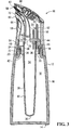
- a dispenser 10 in accordance with the invention is shown, the dispenser 10 being suitable for dispensing oil and vinegar simultaneously.
- the dispenser 10 has an outer container 12 having a bottom wall 14 and a peripheral wall 16 defining an internal space 18 for receiving the oil.
- the outer container 12 also comprises a neck 20 provided at its top end, the neck 20 having external threads 22 and a top rim 24 defining an opening 26.
- the dispenser 10 further comprises an inner container 28 having a bottom wall 30 and a peripheral wall 32 defining an internal space 34 for receiving the vinegar.
- the inner container 28 also comprises a plurality of arms 36 that project outwardly from the peripheral wall 32 and a peripheral ring 38 having a shoulder 40 projecting outwardly at its top end and being located above the top rim 24 of the outer container 12.
- the inner container 28 has therefore a plurality of openings 42 defined between the peripheral wall 32, arms 36 and peripheral ring 38.
- the inner container 28 has a top rim 44 with a portion located above the shoulder 40 and defining an opening 46.
- the inner container can have a plurality of arms (four or five arms for example) that extend from the peripheral wall 32 up to the peripheral ring 38 for defining the plurality of openings 42 between the peripheral wall 32, arms 36 and peripheral ring 38 wherein the openings 42 allow passage of the oil contained in the internal space 18 of the outer container 12 when the dispenser is tilted.
- the dispenser 10 also comprises a seal (O-ring/gasket) 48 encircling the peripheral ring 38 and mounted between the upper surface of the top rim 24 of the outer container 12 and the bottom surface of the shoulder 40 of the inner container 28.
- a seal O-ring/gasket
- the dispenser 10 has a cap 50 comprising a top wall 50 and a peripheral wall 52 for enclosing the neck 20 of the outer container 12 and the shoulder 40 of the inner container 28 and defining an internal space 54 inside the cap 50.
- the cap 50 also has internal threads 56 registering with the external threads 22 of the outer container 12 such that a user can screw and unscrew the cap 50 on the outer container 12.
- the peripheral wall 52 of the cap 50 further comprises first and second apertures 53, 55 within which first and second spouts 58, 60 are received.
- the first spout 58 has a distal end portion 58D projecting outwardly from the cap and a proximal end portion 58P located within the internal space 54 of the cap and the second spout 60 has a distal end portion 60D projecting outwardly from the cap and a proximal end portion 60P located within the internal space 54 of the cap.
- the cap may comprise a base having a slot for allowing communication between the internal space 54 of the cap 50 and the internal spaces 18, 34 of the outer and inner containers 12, 28.
- the dispenser 10 also comprises a first tube 62 having a bottom end 64 defining a bottom opening 66 facing the internal space 18 of the outer container 12 and a top end 68 mounted around the first spout 58, the top end 68 defining a top opening 70.
- the first tube 62 therefore defines a first passage 72 allowing fluid communication between the internal space 18 and the atmosphere such that, in use, a user can dispense oil through the first passage 72 of the first tube 62 when the user tilts the dispenser 10.
- the dispenser 10 also comprises a second tube 74 having a bottom end 76 defining a bottom opening 78 facing the internal space 34 of the inner container 28 and a top end 80 mounted around the second spout 60, the top end 80 defining a top opening 82.
- the second tube 74 therefore defines a second passage 84 allowing fluid communication between the internal space 34 and the atmosphere such that, in use, the user can dispense vinegar through the second passage 84 of the second tube 74 when the user tilts the dispenser 10.
- the top end 68 of the first tube 62 may be mounted around the proximal end portion 58P of the first spout 58 and the top end 80 of the second tube 74 may be mounted around the proximal end portion 60P of the second spout 60.
- the dispenser 10 also comprises a first aeration tube 86 having a bottom end 88 defining a bottom opening 90 facing the internal space 18 of the outer container 12 and a top end 92 located in the internal space 54 of the cap 50, the top end 92 defining a top opening 94.
- the first aeration tube 86 therefore defines a first air passage 96 such that, in use, when oil is dispensed through the first passage 72 of the first tube 62, air can also penetrate into the internal space 18 of the outer container 12 to replace the volume of oil being dispensed out. As a result, oil can dispense out through the first passage 72 of the first tube 62 smoothly, without the risk of bubbles interrupting the flow.
- the dispenser 10 further comprises a second aeration tube 98 having a bottom end 100 defining a bottom opening 102 facing the internal space 34 of the inner container 28 and a top end 104 located in the internal space 54 of the cap 50, the top end 104 defining a top opening 106.
- the second aeration tube 98 therefore defines a second air passage 108 such that, in use, when vinegar is dispensed through the second passage 84 of the second tube 74, air can also penetrate into the internal space 34 of the inner container 28 to replace the volume of vinegar being dispensed out. As a result, vinegar can dispense out through the second passage 84 of the second tube 74 smoothly, without the risk of bubbles interrupting the flow.
- the inner and outer containers 12, 28 may be made of transparent plastic or glass and the cap 50 may be made of aluminum, plastic or stainless steel.
- the first and second tubes 62, 74 and the first and second aeration tubes 86 and 98 can be part of a unitary member 110 made of an elastomeric material such as food grade silicone.
- the member 110 has a base 112 for covering the shoulder 40 of the inner container 28 and for overlapping the plurality of openings 42 and first and second inner peripheral walls 114, 116 defining therebetween a groove 118 for receiving the top rim 44 of the inner container 28.
- the periphery of the base 112 is pressed against the shoulder 40 when the cap 50 is attached to the outer container 28 preventing the oil within the internal space 18 from going into the internal space 54 within the cap 50 when the dispenser 10 is tilted.
- an internal peripheral shoulder of the cap presses against the periphery of the base 112 that is pushed against the upper surface of the shoulder 40 so as to create a substantially fluid-tight seal between the member 110 and the inner container 12 and between the inner container 12 and the outer container 28.
- the first and second tubes 62, 74 allow separate and simultaneous dispensing of oil and vinegar wherein the oil contained in the internal space 18 of the outer container 12 passes through the opening 26 of the outer container 12 and through at least one of the plurality of openings 42 such that the oil is directed towards the bottom opening 66 of the first tube 62 for allowing dispending of the oil through the first passage 72 of the first tube 62 while air can also penetrate into the internal space 18 of the outer container 12 via the first air passage 96 of the first aeration tube 92 and wherein the vinegar contained in the internal space 34 of the inner container 28 passes through the opening 46 of the inner container 28 and is directed towards the bottom opening 78 of the second tube 74 for allowing dispensing of the vinegar through the second passage 84 of the second tube 74 while air can also penetrate into the internal space 34 of the inner container28 via the second air passage 108 of the second aeration tube 104.
- the dispenser 10 also comprise a first valve for reducing flow of oil and a second valve for reducing flow of vinegar.
- the top wall 51 has a first actuator (push-button) 120 mounted in an aperture, the first actuator 120 being connected to a stem 122 wherein, upon pressure by the user on the first actuator 120, the stem 122 presses on the first tube 62 for reducing flow of oil via the first passage 72.
- the user can stop the flow of oil as shown in Figure 4A .
- the top wall 51 has a second actuator (push-button) 124 mounted in another aperture, the second actuator 124 being connected to a pressing member 126, wherein, upon pressure by the user on the second actuator 124, the pressing member 126 presses on the second tube 74 for reducing flow of vinegar via the second passage 84.
- the user can stop the flow of vinegar as shown in Figure 4B .
- the diameter of the first tube 62 reduces gradually from the bottom end 64 to the top end 68 such that the first tube 62 gradually tempers up to the top opening 70 in order to maximize the flow of the oil.
- the diameter of the second tube 74 reduces gradually from the bottom end 76 to the top end 80 such that the second tube 74 gradually tempers up to the top opening 82 in order to maximize the flow of the vinegar.
- the diameter of the first tube 62 between the bottom and top ends 64, 68 may reduce of about 90% to 70%
- the one of the second tube 74 between the bottom and top ends 76, 80 may reduce of about 40% to 10% such that different ratios between the oil and vinegar can be obtained when selecting the appropriate diameters and tempering of the first and second tubes 62, 74.
- the length and tempering of the first and second tubes 62, 74 can be selected such that the ratio of oil for vinegar is from 6 for 1 up to 12 for 1.
- the diameter of the first tube 62 may be between 0.300" and 0.340" at the bottom end and between 0.195" and 0.235" at the upper end and the diameter of the second tube 74 may be between 0.293" and 0.333" at the bottom end and between 0.040" and 0.080" at the upper end and the length of the first tube 62 may be between 2.2" and 2.6" and the length of the second tube 74 may be between 2.8" and 3.2".
Landscapes
- Engineering & Computer Science (AREA)
- Mechanical Engineering (AREA)
- Closures For Containers (AREA)
- Table Devices Or Equipment (AREA)
Applications Claiming Priority (1)
| Application Number | Priority Date | Filing Date | Title |
|---|---|---|---|
| US30861410P | 2010-02-26 | 2010-02-26 |
Publications (2)
| Publication Number | Publication Date |
|---|---|
| EP2361848A1 true EP2361848A1 (de) | 2011-08-31 |
| EP2361848B1 EP2361848B1 (de) | 2012-09-19 |
Family
ID=43929083
Family Applications (2)
| Application Number | Title | Priority Date | Filing Date |
|---|---|---|---|
| EP20110155853 Not-in-force EP2361848B1 (de) | 2010-02-26 | 2011-02-24 | Öl- und Essigspender |
| EP20110156101 Not-in-force EP2361845B1 (de) | 2010-02-26 | 2011-02-25 | Spender für Lebensmittel-Dressing |
Family Applications After (1)
| Application Number | Title | Priority Date | Filing Date |
|---|---|---|---|
| EP20110156101 Not-in-force EP2361845B1 (de) | 2010-02-26 | 2011-02-25 | Spender für Lebensmittel-Dressing |
Country Status (3)
| Country | Link |
|---|---|
| US (2) | US8827123B2 (de) |
| EP (2) | EP2361848B1 (de) |
| CA (2) | CA2732363A1 (de) |
Cited By (2)
| Publication number | Priority date | Publication date | Assignee | Title |
|---|---|---|---|---|
| WO2013093392A1 (en) | 2011-12-20 | 2013-06-27 | Ben Tagoe | Liquid pourer |
| RU2494944C1 (ru) * | 2012-06-21 | 2013-10-10 | Антон Аркадьевич Шапиро | Устройство для приготовления топливной смеси для двигателей внутреннего сгорания |
Families Citing this family (12)
| Publication number | Priority date | Publication date | Assignee | Title |
|---|---|---|---|---|
| USD673448S1 (en) * | 2011-03-04 | 2013-01-01 | S. C. Johnson & Son, Inc. | Container shroud |
| FR3019532B1 (fr) * | 2014-04-08 | 2017-10-06 | Qualipac Sa | Flacon, systeme comprenant un tel flacon et leur procede de fabrication. |
| USD763086S1 (en) | 2014-09-18 | 2016-08-09 | Prestone Products Corporation | Coolant additive package |
| US10617244B1 (en) * | 2015-04-16 | 2020-04-14 | Aron J. LANTZ | Easymeal food and drink dispensing device |
| WO2016196639A1 (en) * | 2015-06-01 | 2016-12-08 | Double Take Containers, Llc | Multi-chambered shot container |
| CN104958019B (zh) * | 2015-06-25 | 2017-11-10 | 南安泛科轴承检测技术有限公司 | 可调配液体的调味瓶 |
| ES2595243B1 (es) * | 2016-09-16 | 2017-04-06 | Caviaroli, S.L. | Procedimiento de envasado de capsulas alimenticias y producto alimenticio envasado obtenido mediante el mismo |
| DE102017200772A1 (de) * | 2017-01-18 | 2018-07-19 | Wmf Group Gmbh | Isolierkannendeckel und Verwendungen hiervon |
| US11718453B2 (en) * | 2017-10-13 | 2023-08-08 | The Pure Pour Llc | System and coupling device for pouring |
| USD878002S1 (en) * | 2017-10-31 | 2020-03-10 | Sky Urns, Inc. | Pet Urn |
| US10849445B2 (en) | 2018-05-01 | 2020-12-01 | Upslope Brands, Inc. | Beverage container |
| WO2024064978A1 (de) * | 2022-09-29 | 2024-04-04 | Grabher Rene | Behälterkopf |
Citations (5)
| Publication number | Priority date | Publication date | Assignee | Title |
|---|---|---|---|---|
| DE3514133A1 (de) * | 1985-04-19 | 1986-10-23 | Wella Ag, 6100 Darmstadt | Mehrkammerbehaelter |
| EP0342453A1 (de) * | 1988-05-18 | 1989-11-23 | Henkel Kommanditgesellschaft auf Aktien | Mehrkomponentenbehältnis |
| EP1367003A1 (de) * | 2001-02-26 | 2003-12-03 | Kao Corporation | Behälter |
| WO2007053970A1 (de) * | 2005-11-08 | 2007-05-18 | Belcap Switzerland Ag | Behälter-verschluss zum gleichzeitigen ausgiessen zweier separater flüssigkeiten in einem bestimmten mengenverhältnis |
| EP1826144A2 (de) * | 2006-02-27 | 2007-08-29 | Rieke Corporation | Spenderbehälter für zwei fließfähige Produkte |
Family Cites Families (28)
| Publication number | Priority date | Publication date | Assignee | Title |
|---|---|---|---|---|
| US1436708A (en) * | 1922-04-03 | 1922-11-28 | John H Goebel | Pouring nozzle for bottles |
| US1509360A (en) * | 1924-02-14 | 1924-09-23 | David D Lewis | Dispensing can |
| US2099292A (en) * | 1936-08-25 | 1937-11-16 | Mortimer J Brown | Dripless dispensing device |
| US2197995A (en) * | 1937-04-06 | 1940-04-23 | Dill Mfg Co | Valve |
| GB587994A (en) * | 1945-01-01 | 1947-05-12 | Harry Milman Bickle | Improvements relating to stoppers for bottles and other containers |
| US2780391A (en) * | 1952-09-24 | 1957-02-05 | Baker Chem Co J T | Spout comprising a large outlet passage and a smaller outlet passage located therein |
| US2727644A (en) * | 1953-07-02 | 1955-12-20 | Theodore A Giannos | Pouring cap |
| US2808182A (en) * | 1954-11-15 | 1957-10-01 | Leonard Altman | Pouring stopper |
| US2825495A (en) * | 1955-03-18 | 1958-03-04 | Fazio Angelo | Screw top liquor dispenser for bottles |
| GB978453A (en) * | 1962-10-05 | 1964-12-23 | Schenley Ind Inc | An improved container closure and pouring device |
| US3347420A (en) * | 1965-08-16 | 1967-10-17 | Robert J Donoghue | Multi-compartment container for dispensing measured quantities of a plurality of liquids |
| US3386626A (en) * | 1967-02-09 | 1968-06-04 | Kearney Patrick | Non-refillable bottle and pourer |
| US3613955A (en) * | 1969-07-15 | 1971-10-19 | Monsanto Co | Compartmentalized container package |
| DE3208666A1 (de) * | 1982-03-10 | 1983-09-22 | Siemens AG, 1000 Berlin und 8000 München | Zahnaerztliches spritzhandstueck |
| US4596341A (en) * | 1985-09-18 | 1986-06-24 | The Coca-Cola Company | Toy drinking cup |
| DE3731242A1 (de) * | 1987-09-17 | 1989-03-30 | Joka Kathetertechnik Gmbh | Absperrvorrichtung an einer fluessigkeitsentnahme- oder infusionseinrichtung |
| GB8727678D0 (en) * | 1987-11-26 | 1987-12-31 | Goodall D T | Pouring device |
| US5062550A (en) * | 1990-05-24 | 1991-11-05 | Singh Bharat H | Selective flow dispensing container |
| US5511700A (en) * | 1994-07-18 | 1996-04-30 | Ouno; Taiichi | Table pot for liquid seasoning |
| US5931356A (en) * | 1997-06-27 | 1999-08-03 | Dart Industries Inc. | Dispenser for oil/vinegar bottle |
| FR2775956B1 (fr) * | 1998-03-16 | 2000-06-02 | John Genthon | Antigoutte a liquide a fixation exterieur |
| DE19917622C2 (de) * | 1999-04-19 | 2001-05-17 | Ferton Holding Sa | Quetschventil |
| US6398077B1 (en) * | 2000-02-11 | 2002-06-04 | Seaquist Closures Foreign, Inc. | Package with multiple chambers and valves |
| US7731062B2 (en) * | 2000-09-22 | 2010-06-08 | Gebauer Company | Apparatus and method for dispensing liquids |
| CN101622180B (zh) * | 2006-09-22 | 2011-12-07 | 尼科塔股份有限公司 | 流体分配器及分配流体的方法 |
| US7665631B2 (en) * | 2006-11-29 | 2010-02-23 | Dan Pikowski | Double chamber variable condiment dispenser bottle |
| US20080277419A1 (en) * | 2006-12-21 | 2008-11-13 | Chef'n Corporation | Fluid Dispenser |
| US7594589B2 (en) * | 2007-06-14 | 2009-09-29 | Owens-Brockway Glass Container Inc. | Dual-container package and a dispensing closure for such package |
-
2011
- 2011-02-22 CA CA 2732363 patent/CA2732363A1/en not_active Abandoned
- 2011-02-24 EP EP20110155853 patent/EP2361848B1/de not_active Not-in-force
- 2011-02-25 US US13/035,333 patent/US8827123B2/en not_active Expired - Fee Related
- 2011-02-25 EP EP20110156101 patent/EP2361845B1/de not_active Not-in-force
- 2011-02-25 CA CA 2732815 patent/CA2732815A1/en not_active Abandoned
- 2011-02-25 US US13/034,742 patent/US8690015B2/en not_active Expired - Fee Related
Patent Citations (5)
| Publication number | Priority date | Publication date | Assignee | Title |
|---|---|---|---|---|
| DE3514133A1 (de) * | 1985-04-19 | 1986-10-23 | Wella Ag, 6100 Darmstadt | Mehrkammerbehaelter |
| EP0342453A1 (de) * | 1988-05-18 | 1989-11-23 | Henkel Kommanditgesellschaft auf Aktien | Mehrkomponentenbehältnis |
| EP1367003A1 (de) * | 2001-02-26 | 2003-12-03 | Kao Corporation | Behälter |
| WO2007053970A1 (de) * | 2005-11-08 | 2007-05-18 | Belcap Switzerland Ag | Behälter-verschluss zum gleichzeitigen ausgiessen zweier separater flüssigkeiten in einem bestimmten mengenverhältnis |
| EP1826144A2 (de) * | 2006-02-27 | 2007-08-29 | Rieke Corporation | Spenderbehälter für zwei fließfähige Produkte |
Cited By (2)
| Publication number | Priority date | Publication date | Assignee | Title |
|---|---|---|---|---|
| WO2013093392A1 (en) | 2011-12-20 | 2013-06-27 | Ben Tagoe | Liquid pourer |
| RU2494944C1 (ru) * | 2012-06-21 | 2013-10-10 | Антон Аркадьевич Шапиро | Устройство для приготовления топливной смеси для двигателей внутреннего сгорания |
Also Published As
| Publication number | Publication date |
|---|---|
| CA2732363A1 (en) | 2011-08-26 |
| US20110253745A1 (en) | 2011-10-20 |
| US20120048896A1 (en) | 2012-03-01 |
| US8827123B2 (en) | 2014-09-09 |
| CA2732815A1 (en) | 2011-08-26 |
| EP2361845B1 (de) | 2014-05-07 |
| EP2361848B1 (de) | 2012-09-19 |
| US8690015B2 (en) | 2014-04-08 |
| EP2361845A1 (de) | 2011-08-31 |
Similar Documents
| Publication | Publication Date | Title |
|---|---|---|
| EP2361848B1 (de) | Öl- und Essigspender | |
| US8365960B1 (en) | Multi-compartment beverage container | |
| US8261929B2 (en) | Multiple-opening container and method | |
| US9345639B2 (en) | System for facilitating preparation of medication doses | |
| US20070075081A1 (en) | Reusable container with flavor chamber in lid | |
| US20110233236A1 (en) | Continuous, complete, automatic, non-leaking, non-aerating, positive pressure one-piece vent and pouring combination utilizing one direct venting aperture | |
| US5897037A (en) | Combination cap and dispensing spout assembly | |
| US20110031279A1 (en) | Device for measuring and dispensing a prescribed amount of liquid | |
| US20080277419A1 (en) | Fluid Dispenser | |
| US20190329276A1 (en) | Fluid metering and dispenser device | |
| CN1106993C (zh) | 混合饮料容器 | |
| US9986872B2 (en) | Mixing container | |
| US10479570B2 (en) | Bottle and cap assembly for selectively dispensing one beverage into another beverage | |
| RU2234848C1 (ru) | Устройство для употребления композиции, представляющей собой напиток, состоящий как минимум из двух компонентов | |
| US20060091164A1 (en) | Proportioning container | |
| WO2007103503A1 (en) | Multiple-opening container and method | |
| US12030709B2 (en) | Nested fluid dispensing system | |
| US11820548B2 (en) | Multi-compartment bottle system | |
| US20140339253A1 (en) | Liquid pourer | |
| CN224076115U (zh) | 一种可控式即时调配瓶盖及包括其的包装容器和酒类饮品 | |
| GB2596036A (en) | Skin channel multi connected bottle/receptacle system | |
| IT202300005190U1 (it) | Caraffa multi-contenitore con selezionatore di bevand | |
| ES1071463U (es) | Recipiente dispensador de condimentos alimenticios liquidos. | |
| US20130161362A1 (en) | Neck Extender Device | |
| MXPA00008231A (es) | Envase para bebida mixto |
Legal Events
| Date | Code | Title | Description |
|---|---|---|---|
| PUAI | Public reference made under article 153(3) epc to a published international application that has entered the european phase |
Free format text: ORIGINAL CODE: 0009012 |
|
| AK | Designated contracting states |
Kind code of ref document: A1 Designated state(s): AL AT BE BG CH CY CZ DE DK EE ES FI FR GB GR HR HU IE IS IT LI LT LU LV MC MK MT NL NO PL PT RO RS SE SI SK SM TR |
|
| AX | Request for extension of the european patent |
Extension state: BA ME |
|
| 17P | Request for examination filed |
Effective date: 20111024 |
|
| GRAP | Despatch of communication of intention to grant a patent |
Free format text: ORIGINAL CODE: EPIDOSNIGR1 |
|
| GRAS | Grant fee paid |
Free format text: ORIGINAL CODE: EPIDOSNIGR3 |
|
| GRAA | (expected) grant |
Free format text: ORIGINAL CODE: 0009210 |
|
| AK | Designated contracting states |
Kind code of ref document: B1 Designated state(s): AL AT BE BG CH CY CZ DE DK EE ES FI FR GB GR HR HU IE IS IT LI LT LU LV MC MK MT NL NO PL PT RO RS SE SI SK SM TR |
|
| REG | Reference to a national code |
Ref country code: GB Ref legal event code: FG4D |
|
| REG | Reference to a national code |
Ref country code: CH Ref legal event code: EP |
|
| REG | Reference to a national code |
Ref country code: IE Ref legal event code: FG4D |
|
| REG | Reference to a national code |
Ref country code: AT Ref legal event code: REF Ref document number: 575886 Country of ref document: AT Kind code of ref document: T Effective date: 20121015 |
|
| REG | Reference to a national code |
Ref country code: DE Ref legal event code: R096 Ref document number: 602011000225 Country of ref document: DE Effective date: 20121115 |
|
| PG25 | Lapsed in a contracting state [announced via postgrant information from national office to epo] |
Ref country code: LT Free format text: LAPSE BECAUSE OF FAILURE TO SUBMIT A TRANSLATION OF THE DESCRIPTION OR TO PAY THE FEE WITHIN THE PRESCRIBED TIME-LIMIT Effective date: 20120919 Ref country code: FI Free format text: LAPSE BECAUSE OF FAILURE TO SUBMIT A TRANSLATION OF THE DESCRIPTION OR TO PAY THE FEE WITHIN THE PRESCRIBED TIME-LIMIT Effective date: 20120919 Ref country code: NO Free format text: LAPSE BECAUSE OF FAILURE TO SUBMIT A TRANSLATION OF THE DESCRIPTION OR TO PAY THE FEE WITHIN THE PRESCRIBED TIME-LIMIT Effective date: 20121219 Ref country code: HR Free format text: LAPSE BECAUSE OF FAILURE TO SUBMIT A TRANSLATION OF THE DESCRIPTION OR TO PAY THE FEE WITHIN THE PRESCRIBED TIME-LIMIT Effective date: 20120919 |
|
| REG | Reference to a national code |
Ref country code: NL Ref legal event code: VDEP Effective date: 20120919 |
|
| REG | Reference to a national code |
Ref country code: AT Ref legal event code: MK05 Ref document number: 575886 Country of ref document: AT Kind code of ref document: T Effective date: 20120919 |
|
| REG | Reference to a national code |
Ref country code: LT Ref legal event code: MG4D Effective date: 20120919 |
|
| PG25 | Lapsed in a contracting state [announced via postgrant information from national office to epo] |
Ref country code: GR Free format text: LAPSE BECAUSE OF FAILURE TO SUBMIT A TRANSLATION OF THE DESCRIPTION OR TO PAY THE FEE WITHIN THE PRESCRIBED TIME-LIMIT Effective date: 20121220 Ref country code: SI Free format text: LAPSE BECAUSE OF FAILURE TO SUBMIT A TRANSLATION OF THE DESCRIPTION OR TO PAY THE FEE WITHIN THE PRESCRIBED TIME-LIMIT Effective date: 20120919 Ref country code: SE Free format text: LAPSE BECAUSE OF FAILURE TO SUBMIT A TRANSLATION OF THE DESCRIPTION OR TO PAY THE FEE WITHIN THE PRESCRIBED TIME-LIMIT Effective date: 20120919 Ref country code: LV Free format text: LAPSE BECAUSE OF FAILURE TO SUBMIT A TRANSLATION OF THE DESCRIPTION OR TO PAY THE FEE WITHIN THE PRESCRIBED TIME-LIMIT Effective date: 20120919 |
|
| PG25 | Lapsed in a contracting state [announced via postgrant information from national office to epo] |
Ref country code: RO Free format text: LAPSE BECAUSE OF FAILURE TO SUBMIT A TRANSLATION OF THE DESCRIPTION OR TO PAY THE FEE WITHIN THE PRESCRIBED TIME-LIMIT Effective date: 20120919 Ref country code: NL Free format text: LAPSE BECAUSE OF FAILURE TO SUBMIT A TRANSLATION OF THE DESCRIPTION OR TO PAY THE FEE WITHIN THE PRESCRIBED TIME-LIMIT Effective date: 20120919 Ref country code: BE Free format text: LAPSE BECAUSE OF FAILURE TO SUBMIT A TRANSLATION OF THE DESCRIPTION OR TO PAY THE FEE WITHIN THE PRESCRIBED TIME-LIMIT Effective date: 20120919 Ref country code: CZ Free format text: LAPSE BECAUSE OF FAILURE TO SUBMIT A TRANSLATION OF THE DESCRIPTION OR TO PAY THE FEE WITHIN THE PRESCRIBED TIME-LIMIT Effective date: 20120919 Ref country code: EE Free format text: LAPSE BECAUSE OF FAILURE TO SUBMIT A TRANSLATION OF THE DESCRIPTION OR TO PAY THE FEE WITHIN THE PRESCRIBED TIME-LIMIT Effective date: 20120919 Ref country code: IS Free format text: LAPSE BECAUSE OF FAILURE TO SUBMIT A TRANSLATION OF THE DESCRIPTION OR TO PAY THE FEE WITHIN THE PRESCRIBED TIME-LIMIT Effective date: 20130119 |
|
| PG25 | Lapsed in a contracting state [announced via postgrant information from national office to epo] |
Ref country code: PL Free format text: LAPSE BECAUSE OF FAILURE TO SUBMIT A TRANSLATION OF THE DESCRIPTION OR TO PAY THE FEE WITHIN THE PRESCRIBED TIME-LIMIT Effective date: 20120919 Ref country code: SK Free format text: LAPSE BECAUSE OF FAILURE TO SUBMIT A TRANSLATION OF THE DESCRIPTION OR TO PAY THE FEE WITHIN THE PRESCRIBED TIME-LIMIT Effective date: 20120919 Ref country code: PT Free format text: LAPSE BECAUSE OF FAILURE TO SUBMIT A TRANSLATION OF THE DESCRIPTION OR TO PAY THE FEE WITHIN THE PRESCRIBED TIME-LIMIT Effective date: 20130121 |
|
| PG25 | Lapsed in a contracting state [announced via postgrant information from national office to epo] |
Ref country code: AT Free format text: LAPSE BECAUSE OF FAILURE TO SUBMIT A TRANSLATION OF THE DESCRIPTION OR TO PAY THE FEE WITHIN THE PRESCRIBED TIME-LIMIT Effective date: 20120919 |
|
| PLBE | No opposition filed within time limit |
Free format text: ORIGINAL CODE: 0009261 |
|
| STAA | Information on the status of an ep patent application or granted ep patent |
Free format text: STATUS: NO OPPOSITION FILED WITHIN TIME LIMIT |
|
| PG25 | Lapsed in a contracting state [announced via postgrant information from national office to epo] |
Ref country code: BG Free format text: LAPSE BECAUSE OF FAILURE TO SUBMIT A TRANSLATION OF THE DESCRIPTION OR TO PAY THE FEE WITHIN THE PRESCRIBED TIME-LIMIT Effective date: 20121219 Ref country code: RS Free format text: LAPSE BECAUSE OF FAILURE TO SUBMIT A TRANSLATION OF THE DESCRIPTION OR TO PAY THE FEE WITHIN THE PRESCRIBED TIME-LIMIT Effective date: 20120919 Ref country code: DK Free format text: LAPSE BECAUSE OF FAILURE TO SUBMIT A TRANSLATION OF THE DESCRIPTION OR TO PAY THE FEE WITHIN THE PRESCRIBED TIME-LIMIT Effective date: 20120919 |
|
| 26N | No opposition filed |
Effective date: 20130620 |
|
| PG25 | Lapsed in a contracting state [announced via postgrant information from national office to epo] |
Ref country code: IT Free format text: LAPSE BECAUSE OF FAILURE TO SUBMIT A TRANSLATION OF THE DESCRIPTION OR TO PAY THE FEE WITHIN THE PRESCRIBED TIME-LIMIT Effective date: 20120919 |
|
| PG25 | Lapsed in a contracting state [announced via postgrant information from national office to epo] |
Ref country code: MC Free format text: LAPSE BECAUSE OF NON-PAYMENT OF DUE FEES Effective date: 20130228 |
|
| REG | Reference to a national code |
Ref country code: DE Ref legal event code: R097 Ref document number: 602011000225 Country of ref document: DE Effective date: 20130620 |
|
| PG25 | Lapsed in a contracting state [announced via postgrant information from national office to epo] |
Ref country code: ES Free format text: LAPSE BECAUSE OF FAILURE TO SUBMIT A TRANSLATION OF THE DESCRIPTION OR TO PAY THE FEE WITHIN THE PRESCRIBED TIME-LIMIT Effective date: 20121230 |
|
| PG25 | Lapsed in a contracting state [announced via postgrant information from national office to epo] |
Ref country code: CY Free format text: LAPSE BECAUSE OF FAILURE TO SUBMIT A TRANSLATION OF THE DESCRIPTION OR TO PAY THE FEE WITHIN THE PRESCRIBED TIME-LIMIT Effective date: 20120919 |
|
| REG | Reference to a national code |
Ref country code: IE Ref legal event code: MM4A |
|
| PG25 | Lapsed in a contracting state [announced via postgrant information from national office to epo] |
Ref country code: IE Free format text: LAPSE BECAUSE OF NON-PAYMENT OF DUE FEES Effective date: 20130224 Ref country code: AL Free format text: LAPSE BECAUSE OF FAILURE TO SUBMIT A TRANSLATION OF THE DESCRIPTION OR TO PAY THE FEE WITHIN THE PRESCRIBED TIME-LIMIT Effective date: 20120919 |
|
| PGFP | Annual fee paid to national office [announced via postgrant information from national office to epo] |
Ref country code: FR Payment date: 20140220 Year of fee payment: 4 |
|
| PG25 | Lapsed in a contracting state [announced via postgrant information from national office to epo] |
Ref country code: MT Free format text: LAPSE BECAUSE OF FAILURE TO SUBMIT A TRANSLATION OF THE DESCRIPTION OR TO PAY THE FEE WITHIN THE PRESCRIBED TIME-LIMIT Effective date: 20120919 |
|
| PGFP | Annual fee paid to national office [announced via postgrant information from national office to epo] |
Ref country code: DE Payment date: 20140227 Year of fee payment: 4 |
|
| REG | Reference to a national code |
Ref country code: CH Ref legal event code: PL |
|
| PG25 | Lapsed in a contracting state [announced via postgrant information from national office to epo] |
Ref country code: CH Free format text: LAPSE BECAUSE OF NON-PAYMENT OF DUE FEES Effective date: 20140228 Ref country code: LI Free format text: LAPSE BECAUSE OF NON-PAYMENT OF DUE FEES Effective date: 20140228 |
|
| PG25 | Lapsed in a contracting state [announced via postgrant information from national office to epo] |
Ref country code: SM Free format text: LAPSE BECAUSE OF FAILURE TO SUBMIT A TRANSLATION OF THE DESCRIPTION OR TO PAY THE FEE WITHIN THE PRESCRIBED TIME-LIMIT Effective date: 20120919 |
|
| PG25 | Lapsed in a contracting state [announced via postgrant information from national office to epo] |
Ref country code: TR Free format text: LAPSE BECAUSE OF FAILURE TO SUBMIT A TRANSLATION OF THE DESCRIPTION OR TO PAY THE FEE WITHIN THE PRESCRIBED TIME-LIMIT Effective date: 20120919 |
|
| PG25 | Lapsed in a contracting state [announced via postgrant information from national office to epo] |
Ref country code: MK Free format text: LAPSE BECAUSE OF FAILURE TO SUBMIT A TRANSLATION OF THE DESCRIPTION OR TO PAY THE FEE WITHIN THE PRESCRIBED TIME-LIMIT Effective date: 20120919 Ref country code: HU Free format text: LAPSE BECAUSE OF FAILURE TO SUBMIT A TRANSLATION OF THE DESCRIPTION OR TO PAY THE FEE WITHIN THE PRESCRIBED TIME-LIMIT; INVALID AB INITIO Effective date: 20110224 Ref country code: LU Free format text: LAPSE BECAUSE OF NON-PAYMENT OF DUE FEES Effective date: 20130224 |
|
| REG | Reference to a national code |
Ref country code: DE Ref legal event code: R119 Ref document number: 602011000225 Country of ref document: DE |
|
| GBPC | Gb: european patent ceased through non-payment of renewal fee |
Effective date: 20150224 |
|
| REG | Reference to a national code |
Ref country code: FR Ref legal event code: ST Effective date: 20151030 |
|
| PG25 | Lapsed in a contracting state [announced via postgrant information from national office to epo] |
Ref country code: DE Free format text: LAPSE BECAUSE OF NON-PAYMENT OF DUE FEES Effective date: 20150901 Ref country code: GB Free format text: LAPSE BECAUSE OF NON-PAYMENT OF DUE FEES Effective date: 20150224 |
|
| PG25 | Lapsed in a contracting state [announced via postgrant information from national office to epo] |
Ref country code: FR Free format text: LAPSE BECAUSE OF NON-PAYMENT OF DUE FEES Effective date: 20150302 |