EP2361860A2 - Dispositif de prise sous pression - Google Patents
Dispositif de prise sous pression Download PDFInfo
- Publication number
- EP2361860A2 EP2361860A2 EP10196200A EP10196200A EP2361860A2 EP 2361860 A2 EP2361860 A2 EP 2361860A2 EP 10196200 A EP10196200 A EP 10196200A EP 10196200 A EP10196200 A EP 10196200A EP 2361860 A2 EP2361860 A2 EP 2361860A2
- Authority
- EP
- European Patent Office
- Prior art keywords
- valve body
- valve
- gripper device
- opening
- plate
- Prior art date
- Legal status (The legal status is an assumption and is not a legal conclusion. Google has not performed a legal analysis and makes no representation as to the accuracy of the status listed.)
- Granted
Links
- 238000000034 method Methods 0.000 claims abstract description 7
- 238000004891 communication Methods 0.000 claims description 2
- 230000008859 change Effects 0.000 description 3
- 239000002184 metal Substances 0.000 description 3
- 238000007789 sealing Methods 0.000 description 3
- 241000239290 Araneae Species 0.000 description 2
- 230000008901 benefit Effects 0.000 description 2
- 238000010276 construction Methods 0.000 description 2
- 230000000284 resting effect Effects 0.000 description 2
- 230000006978 adaptation Effects 0.000 description 1
- 238000005520 cutting process Methods 0.000 description 1
- 238000000151 deposition Methods 0.000 description 1
- 238000001514 detection method Methods 0.000 description 1
- 238000005516 engineering process Methods 0.000 description 1
- 230000002349 favourable effect Effects 0.000 description 1
- 230000001788 irregular Effects 0.000 description 1
- 238000003754 machining Methods 0.000 description 1
- 238000012423 maintenance Methods 0.000 description 1
- 238000004519 manufacturing process Methods 0.000 description 1
- 230000007246 mechanism Effects 0.000 description 1
- 230000002093 peripheral effect Effects 0.000 description 1
- 230000008569 process Effects 0.000 description 1
- 230000035484 reaction time Effects 0.000 description 1
- 230000004044 response Effects 0.000 description 1
- 238000011896 sensitive detection Methods 0.000 description 1
- 238000007493 shaping process Methods 0.000 description 1
- XLYOFNOQVPJJNP-UHFFFAOYSA-N water Substances O XLYOFNOQVPJJNP-UHFFFAOYSA-N 0.000 description 1
Images

Classifications
-
- B—PERFORMING OPERATIONS; TRANSPORTING
- B65—CONVEYING; PACKING; STORING; HANDLING THIN OR FILAMENTARY MATERIAL
- B65G—TRANSPORT OR STORAGE DEVICES, e.g. CONVEYORS FOR LOADING OR TIPPING, SHOP CONVEYOR SYSTEMS OR PNEUMATIC TUBE CONVEYORS
- B65G47/00—Article or material-handling devices associated with conveyors; Methods employing such devices
- B65G47/74—Feeding, transfer, or discharging devices of particular kinds or types
- B65G47/90—Devices for picking-up and depositing articles or materials
- B65G47/91—Devices for picking-up and depositing articles or materials incorporating pneumatic, e.g. suction, grippers
- B65G47/917—Devices for picking-up and depositing articles or materials incorporating pneumatic, e.g. suction, grippers control arrangements
-
- B—PERFORMING OPERATIONS; TRANSPORTING
- B65—CONVEYING; PACKING; STORING; HANDLING THIN OR FILAMENTARY MATERIAL
- B65G—TRANSPORT OR STORAGE DEVICES, e.g. CONVEYORS FOR LOADING OR TIPPING, SHOP CONVEYOR SYSTEMS OR PNEUMATIC TUBE CONVEYORS
- B65G47/00—Article or material-handling devices associated with conveyors; Methods employing such devices
- B65G47/74—Feeding, transfer, or discharging devices of particular kinds or types
- B65G47/90—Devices for picking-up and depositing articles or materials
- B65G47/91—Devices for picking-up and depositing articles or materials incorporating pneumatic, e.g. suction, grippers
Definitions
- the present invention relates to a vacuum gripping device having the features of independent claim 1 and a method for receiving objects.
- a group of gripper devices uses vacuum to pick up objects. Such vacuum gripping devices are often referred to as vacuum grippers. With such grippers, smooth-surfaced objects can be taken up, carried and set down gently again.
- valve housing with therein air channels, at least one vacuum chamber and a valve body arranged therein for closing or releasing an air duct when sucking or depositing the object to be gripped.
- valve variants can be found, for example, in the EP 0 456 884 A2 as well as in the JP 2001-341089 A ,
- valve types which have movable or pivotable flaps for opening and closing air passages within the valve housing.
- a variant with raisable and lowerable valve bodies can be found in the FR 2 709 478 A while the EP 1 671 906 B1 discloses a mechanism with pivoting flaps.
- the DE 697 24 012T2 finally, discloses a vacuum gripping device having a vacuum plate with a vacuum chamber connected to a vacuum generating system in the vacuum chamber.
- the vacuum plate has a flat lower plate with a plurality of openings, the underside of which is provided with an elastic, airtight bottom.
- Within the vacuum chamber is a vertically movable ball, which is able to close the opening located in the plate.
- a bypass channel not captured by the ball should provide a permanent maintenance of the negative pressure in order to lift an article, even if the ball closes the intake passage in the vacuum chamber. As soon as an object to be lifted is detected, the ball drops due to the pressure conditions changing in the vacuum chamber.
- An object of the present invention is to provide a vacuum gripper device which is simple in construction and inexpensive to produce, which on the one hand enables rapid suction of articles and objects to be picked up and, on the other hand, their reliable fixation on the gripper device.
- the present invention proposes a vacuum gripping device with the features of independent claim 1, which has a contact surface for receiving objects and articles, for example.
- a contact surface for receiving objects and articles, for example.
- the contact surface or suction plate has at least one suction opening, which is in communication with an air channel and a valve associated with this air channel, which has a valve body arranged movably within a vacuum chamber located in the air channel with a flow aperture.
- the valve body is preferably substantially freely movable between two end positions within the vacuum chamber, so that it can release the openings of the air duct as needed or largely close with the help of the flow restrictor so as to sensitively address the gripper device as soon as the contact surface on a top of Object is placed in order to accommodate this with sufficient holding power can.
- the vacuum gripper device enables the rapid detection of objects and the rapid change of the end position of the valve depending on the presence of gripping objects. These can be fixed very reliably, which results in particular from the fact that unoccupied suction are largely closed and thus the total vacuum or the entire vacuum built-up does not drop too much or even collapses.
- a contact surface with at least one intake opening is generally mentioned, then it is by no means ruled out that several intake openings and / or several contact areas, each with a suitable number of uniform, possibly in a regular grid over the contact surface, distributed suction available.
- the number and the cross-section of the intake openings depend primarily on the intended use of the gripper device, its load, the size and weight of the objects to be accommodated, etc.
- shape of the lower intake are more Variants possible, for example.
- the openings are designed so that the valve plate in any lower end position conceals the intake as little as possible.
- the majority of the existing intake ports may optionally be connected to a common vacuum source.
- the gripper device designed in this way can optionally be designed as an area gripper by arranging a plurality of suction openings, as a suction spider or as a suction strip.
- elastic elements may be provided for better sealing of the contact surface resting on the objects and their suction openings. These elastic elements may act as suction cups in cooperation with the suction openings.
- the lower intake opening may optionally have a circular or almost any geometric, slot-like, star-shaped or otherwise shaped, non-circular contour.
- the suction opening may be formed by a plurality of smaller openings, which are preferably within a geometric, in particular within a circular outline contour.
- the valve body is in a first end position at an upper opening of the opening into the vacuum chamber air duct and closes it largely to the predetermined by the permeable flow aperture air intake.
- the valve body In its first end position, the valve body is sucked by the pressure prevailing in the air channel vacuum to the upper opening of the air channel.
- the valve body In its second end position, the valve body rests on an inner side of the contact surface with the at least one intake opening located therein while largely freeing the opening cross section of the at least one intake opening.
- the valve body may in particular be formed by a flat valve plate having at least one bore therein as a flow diaphragm.
- the valve body is formed as a flat disc, which can move up and down within the vacuum chamber between the two end positions in order to control the valve located in the gripper device as needed.
- the valve body or the valve plate has a diameter which is smaller than the cross section of the vacuum chamber.
- the total opening cross-section of the flow diaphragm located in the valve body or in the valve plate is less than half, in particular less than a quarter or fifth the opening cross section of the air channel. In this way it can be ensured that the bypass channel, which is formed by the flow restrictor, the valve can respond very quickly.
- the present invention further relates to a method for receiving objects by means of a vacuum gripper device according to one of the previously described embodiments.
- the valve body or the valve plate is as long as at its first upper end position at the upper opening of the opening into the vacuum chamber air duct and closes it to its permeable flow aperture largely until the contact plate is placed from above on an object to be gripped.
- the volume of air within the vacuum chamber is largely evacuated via the flow diaphragm, so that the valve body or the valve plate falls down into the second end position on the inside of the contact plate. In this case, the negative pressure for holding and carrying the object over the larger cross section of the air duct is maintained.
- the gripper can also be operated by occupying a large part of the suction openings with a gripping object, with no vacuum applied to the system. If the vacuum or the vacuum is then turned on, the sealed suction surfaces are evacuated. The valve plate stays down. In the non-sealed suction the valve plates are sucked and thus the air duct largely closed. The overall vacuum is thereby built up faster.
- the vacuum gripper device according to the invention is particularly suitable in its various configurations for use with not exactly definable spatial associations to the objects to be picked up and / or for objects with irregular or not exactly smooth-surfaced shaped upper sides.
- it can be used well if it can not reliably be ensured that all suction elements rest on an object and are thus occupied and thus sealed.
- the gripper device according to the invention provides a remedy by suitable design and dimensioning of the valve body and in particular the flow diaphragm arranged therein.
- the design according to the invention with the preferably plate-shaped, flat valve body and arranged therein, in the non-active state of the gripper still active remaining flow aperture, provides compared to the previously known suction pads, which essentially with a ball and a bypass channel work, the advantage of very sensitive detection of items and objects to be recorded, because when you put the suction cup or the suction pad located in the vacuum chamber plate or ball immediately lowers and activates the necessary negative pressure.
- the valve body is designed as a flat plate made of metal or plastic, this supports the desired response under substantially all operating conditions. If the suction port is not yet completely sealed by the object, the valve body can already be pulled upwards, since in this case the flow through leakage air is normally sufficient to pull the valve plate upwards. If it is up, the negative pressure is built up by the orifice and the vacuum chamber evacuated so far that the plate falls down again to be sucked in again, etc.
- the valve located in the gripper device or the plurality of valves sucks in the idle state, in which it is not yet placed on an object to be gripped, only a small amount of air through the strong drosseInde flow restrictor with its relative to the air-conducting channels in the valve relatively small cross-section ,
- the valve body or the flat valve plate made of metal or plastic is in this case with respect to the suction channel of the valve permeable flow aperture at the mouth of the air channel and closes this largely.
- the resulting suction pressure is thereby greatly reduced, so that the gripper device is in a kind of ready state.
- the lower openings in the contact plate or suction plate, which are placed on the objects to be gripped, are open and let the amount of air flowing through the flow aperture pass unhindered due to their much larger cross-section.
- the so-called leakage air passing through the flow aperture is relatively small, whereby a relatively favorable efficiency is achieved with a fast reaction time.
- the valve of the vacuum gripper device according to the invention offers significant advantages over the previously used vacuum grippers because of its construction.
- the diameters of the air channels, the vacuum chamber and the flow aperture allow adaptation to different purposes and required holding forces.
- the valve requires a low production cost and can be easily and inexpensively made by machining.
- a particularly cost-effective variant can also be produced in layer technology, in which stamped or processed by laser or water jet cutting processes plates are connected in layers by means of screws or other suitable bonding techniques.
- a vacuum valve 10 is explained, which is not the essential part of one here in its entirety Peripheral vacuum gripper device 8 forms.
- the valve 10 or the gripper device 8 have a valve housing 12 and a lower contact surface 14 arranged thereon for receiving objects 16 (cf. Figures 2 and 3 ) on.
- This contact surface 14 is referred to in the present context as the lower suction plate 18.
- the contact surface 14 or suction plate 18 has two intake openings 20, which communicate with an air channel 22 arranged in the valve housing 12.
- a vacuum chamber 24 Between the suction plate 18 and the air channel 22 is a vacuum chamber 24, within which a movably arranged valve body 26 is arranged with a flow aperture 28.
- the plate-shaped or disc-shaped valve body 26 with the flow aperture 28 arranged centrally therein is designed as a flat valve plate 30 or as a valve plate in the illustrated embodiment, which is delimited both on the upper side of the vacuum chamber 24 and on the lower side, which is bounded by the suction plate 18. can rest in a sealing manner.
- the valve plate 30 is thus substantially freely movable between two end positions within the vacuum chamber 24, so that they can open or close the opening of the air duct 22 as needed in order to sensitively address the gripper device 8, as soon as the contact surface 14 on an upper side of the Object 16 is placed in order to accommodate this with sufficient holding power can.
- the air duct 22 and other, not shown here, air ducts of several such valves 10 is / are connected to a vacuum source.
- the gripper device 8 can optionally be formed by arranging a plurality of suction openings 20 as a surface gripper, as so-called. Suction spider or as a suction bar o. The like.
- elastic elements may be provided for better sealing of the contact surface 14 resting on the objects 16 and their suction openings 20. These optional, not shown here, elastic elements may act as suction cups in cooperation with the intake ports 20.
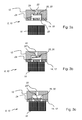
- the valve body 26 and the valve plate 30 is in a first end position (see. Fig. 1 ) at the upper opening of the opening into the vacuum chamber 24 air duct 22 and closes it to the predetermined by the permeable flow aperture 28 air intake.
- the valve body 26 In its first end position, the valve body 26 is sucked by the pressure prevailing in the air duct 22 negative pressure to the upper opening of the air channel 22.
- the valve body 26 In its second end position (cf. Fig. 2 ), the valve body 26 is located on an inner side of the contact surface 14 with the intake openings 20 therein while largely freeing the opening cross-section of the two intake ports 20.
- valve body 26 and the valve plate 30 has an outer diameter which is smaller than the cross section of the vacuum chamber 24.
- the opening cross section of the valve body 26 and in the valve plate 30 flow restrictor 28 is also significantly less than the entire opening cross-section of
- the cross section of the flow aperture 28 is preferably significantly less than half, in particular less than a quarter or fifth of the opening cross-section of the air channel 22nd
- FIG. 3a The representations of the Fig. 3 vividly illustrate the process of contacting and receiving an object 16 by means of the gripper device 8 according to the invention Fig. 3a the valve body 26 and the valve plate 30 as long as at its first, upper end position at the upper opening of the opening into the vacuum chamber 24 air duct 22 and closes it to the cross section of the permeable flow restrictor 28 largely until the contact surface 14 or suction plate 18th is placed from above on the object 16 to be gripped (see. Fig. 3b ), whereby the volume of air within the vacuum chamber 24 is largely evacuated via the flow aperture 28 and the valve body 26 and the valve plate 30 falls down to the second end position on the inside of the contact plate 18.
- the negative pressure for holding and carrying the object 16 is held over the larger cross section of the air channel 22 (cf. Fig. 3c ).
- the valve located in the gripper device 8 10 and the plurality of valves 10 sucks in the idle state, in which it is not yet placed on the object to be gripped 16, only a small amount of air through the strongly throttling flow restrictor 28 with its opposite to the valve 10th located air-conducting channels 20, 22 of relatively small cross-section.
- the valve body 26 and the flat valve plate 30 made of metal or plastic is in this case with respect to the suction channel 22 of the valve 10 permeable flow aperture 28 at the mouth of the air channel 22 and closes it largely.
- the resulting suction pressure is thereby greatly reduced, so that the gripper device 8 is in a kind of ready state.
- the lower openings 20 in the contact plate 14 and suction plate 18, which are placed on the object to be gripped 16, are open and let the amount of air flowing through the flow aperture 28 pass unhindered due to its much larger cross-section.
- the gripper device 8 may optionally have a plurality of suction openings 20 and operated by several or most of the intake ports 20 are occupied by a gripping object 16, wherein initially no appreciable negative pressure applied to the system. If the vacuum or the negative pressure is then switched on, the sealed suction surfaces and covered suction openings 20 are evacuated. The valve plate 30 remains below. In the case of the unsealed suction openings 20, on the other hand, the valve plates 30 are in each case sucked in and moved upwards, whereby the respective air channel 22 is largely closed. The overall vacuum is thereby built up faster.
- the openings 20 are designed so that the valve plate 30 in any lower end position, the intake port 20 as little as possible covered.
- the plurality of existing intake ports 20 may be selectively connected to a common vacuum source.
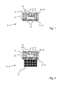
- the presentation of the Fig. 4 shows in a schematic representation of various variants of the design of lower intake ports 20 of the vacuum valve 10 and the grouping of several such suction ports 20 in a gripper device 8.
- the uppermost intake port 20a has the shape of a slot with parallel longitudinal sides and rounded narrow sides
- the second variant of Intake port 20b has two such slots, which are arranged at an angle of 90 ° above each other, so that the suction port 20b has the shape of a cross.
- the third variant 20c shown below has a star shape with three legs of equal length and equal width
- the fourth variant 20d has a modified star shape with relatively broad sections which, for example, can be designed by superimposing three circles.
- the lower intake ports 20 of the valve 10 can also according to the variants shown below 32a, 32b, 32c or 32d of Fig. 4 be grouped.
- the first variant 32a shows three smaller holes that can be arranged in a row next to each other.
- the second variant 32b of the grouping shows a slightly larger central bore and a total of eight spaced apart from this smaller holes, each lying on a ring which is arranged concentrically to the larger central bore.
- numerous small holes are arranged in a regular pattern bounded by an outer circle. Within the circle, the small, each circular holes are arranged in a grid-like pattern.
- the fourth grouping variant 32d shown below is similar to the third variant 32c, but here the bores each have a square or rectangular outline.
Landscapes
- Engineering & Computer Science (AREA)
- Mechanical Engineering (AREA)
- Manipulator (AREA)
- Feeding Of Articles By Means Other Than Belts Or Rollers (AREA)
Applications Claiming Priority (1)
| Application Number | Priority Date | Filing Date | Title |
|---|---|---|---|
| DE102010000526A DE102010000526A1 (de) | 2010-02-24 | 2010-02-24 | Unterdruck-Greifervorrichtung |
Publications (3)
| Publication Number | Publication Date |
|---|---|
| EP2361860A2 true EP2361860A2 (fr) | 2011-08-31 |
| EP2361860A3 EP2361860A3 (fr) | 2013-12-18 |
| EP2361860B1 EP2361860B1 (fr) | 2015-03-18 |
Family
ID=44069964
Family Applications (1)
| Application Number | Title | Priority Date | Filing Date |
|---|---|---|---|
| EP20100196200 Active EP2361860B1 (fr) | 2010-02-24 | 2010-12-21 | Dispositif de préhension par dépression |
Country Status (3)
| Country | Link |
|---|---|
| EP (1) | EP2361860B1 (fr) |
| CN (1) | CN102161436A (fr) |
| DE (1) | DE102010000526A1 (fr) |
Cited By (5)
| Publication number | Priority date | Publication date | Assignee | Title |
|---|---|---|---|---|
| WO2013068307A1 (fr) * | 2011-11-07 | 2013-05-16 | Bdt Media Automation Gmbh | Dispositif pour soulever et positionner un objet |
| EP2653274A1 (fr) | 2012-04-19 | 2013-10-23 | Krones Aktiengesellschaft | Dispositif de préhension à pression négative |
| CN105114440A (zh) * | 2015-07-31 | 2015-12-02 | 苏州市玄天环保科技有限公司 | 一种负压强力吸附装置 |
| CN109173873A (zh) * | 2018-10-31 | 2019-01-11 | 重庆英特力科技有限公司 | 自动振荡混匀装置 |
| CN110877346A (zh) * | 2019-12-16 | 2020-03-13 | 南京极智嘉机器人有限公司 | 一种真空抓取装置及机器人 |
Families Citing this family (9)
| Publication number | Priority date | Publication date | Assignee | Title |
|---|---|---|---|---|
| US8849620B2 (en) | 2011-11-18 | 2014-09-30 | Nike, Inc. | Automated 3-D modeling of shoe parts |
| US8858744B2 (en) | 2011-11-18 | 2014-10-14 | Nike, Inc. | Multi-functional manufacturing tool |
| US9010827B2 (en) * | 2011-11-18 | 2015-04-21 | Nike, Inc. | Switchable plate manufacturing vacuum tool |
| DE102012204577B4 (de) * | 2012-03-22 | 2014-04-03 | Trumpf Werkzeugmaschinen Gmbh + Co. Kg | Sauggreiferanordnung zum Handhaben von Werkstücken, insbesondere von Blechen |
| DE102013222377B3 (de) | 2013-11-04 | 2015-02-19 | J. Schmalz Gmbh | Sauggreifvorrichtung |
| DE202016107328U1 (de) * | 2016-12-23 | 2018-03-26 | Krones Ag | Flexible Vakuumleiste |
| CN110053957A (zh) * | 2019-04-29 | 2019-07-26 | 东莞市鸿仁自动化设备科技有限公司 | 一种薄板的智能化堆叠系统及堆叠方法 |
| CN111791245A (zh) * | 2020-06-17 | 2020-10-20 | 合肥学院 | 一种具有多种夹持状态的五轴搬运机器人机械手臂 |
| CN114383345B (zh) * | 2022-02-28 | 2025-02-07 | 珠海格力电器股份有限公司 | 气液分离器及空调系统 |
Citations (5)
| Publication number | Priority date | Publication date | Assignee | Title |
|---|---|---|---|---|
| EP0456884A2 (fr) | 1990-05-17 | 1991-11-21 | Fsk Inc. | Méthode de maintien d'objets et appareil adapté |
| FR2709478A1 (fr) | 1993-08-30 | 1995-03-10 | Joulin Aero Distribution | Dispositif de préhension et/ou de transport de matériaux. |
| JP2001341089A (ja) | 2000-06-01 | 2001-12-11 | Yasuo Yamanaka | 物品吸着装置およびその方法 |
| DE69724012T2 (de) | 1996-05-24 | 2004-06-09 | Vasserud Ab | Hebevorrichtung |
| EP1671906B1 (fr) | 2004-12-20 | 2009-07-15 | Giacobbe Mazzucchelli | Soupape de pression negative à utiliser dans un dispositif de préhension pour panneaux |
Family Cites Families (4)
| Publication number | Priority date | Publication date | Assignee | Title |
|---|---|---|---|---|
| DE2237943A1 (de) * | 1972-05-10 | 1973-11-22 | Laessig Foerdertech Hamburg | Vorrichtung zum umlagern von foerdergut unter verwendung eines mit einem vakuumerzeuger verbundenen saugkopfes |
| WO1993006973A1 (fr) * | 1991-09-30 | 1993-04-15 | Haruo Konagai | Dispositif d'aspiration |
| JPH11254365A (ja) * | 1998-03-13 | 1999-09-21 | Akiyoshi Kawano | 吸着装置 |
| FR2930766B1 (fr) * | 2008-04-30 | 2010-05-07 | Coval | Appareil de prehension par aspiration |
-
2010
- 2010-02-24 DE DE102010000526A patent/DE102010000526A1/de not_active Withdrawn
- 2010-12-21 EP EP20100196200 patent/EP2361860B1/fr active Active
-
2011
- 2011-02-24 CN CN2011100472032A patent/CN102161436A/zh active Pending
Patent Citations (5)
| Publication number | Priority date | Publication date | Assignee | Title |
|---|---|---|---|---|
| EP0456884A2 (fr) | 1990-05-17 | 1991-11-21 | Fsk Inc. | Méthode de maintien d'objets et appareil adapté |
| FR2709478A1 (fr) | 1993-08-30 | 1995-03-10 | Joulin Aero Distribution | Dispositif de préhension et/ou de transport de matériaux. |
| DE69724012T2 (de) | 1996-05-24 | 2004-06-09 | Vasserud Ab | Hebevorrichtung |
| JP2001341089A (ja) | 2000-06-01 | 2001-12-11 | Yasuo Yamanaka | 物品吸着装置およびその方法 |
| EP1671906B1 (fr) | 2004-12-20 | 2009-07-15 | Giacobbe Mazzucchelli | Soupape de pression negative à utiliser dans un dispositif de préhension pour panneaux |
Cited By (9)
| Publication number | Priority date | Publication date | Assignee | Title |
|---|---|---|---|---|
| WO2013068307A1 (fr) * | 2011-11-07 | 2013-05-16 | Bdt Media Automation Gmbh | Dispositif pour soulever et positionner un objet |
| EP2799385A1 (fr) * | 2011-11-07 | 2014-11-05 | BDT Media Automation GmbH | Dispositif de levage et de positionnement d'un objet |
| US9339936B2 (en) | 2011-11-07 | 2016-05-17 | Bdt Media Automation Gmbh | Device for lifting and positioning an object |
| EP2653274A1 (fr) | 2012-04-19 | 2013-10-23 | Krones Aktiengesellschaft | Dispositif de préhension à pression négative |
| DE102012206469A1 (de) | 2012-04-19 | 2013-10-24 | Krones Aktiengesellschaft | Unterdruck-Greifvorrichtung |
| CN105114440A (zh) * | 2015-07-31 | 2015-12-02 | 苏州市玄天环保科技有限公司 | 一种负压强力吸附装置 |
| CN109173873A (zh) * | 2018-10-31 | 2019-01-11 | 重庆英特力科技有限公司 | 自动振荡混匀装置 |
| CN110877346A (zh) * | 2019-12-16 | 2020-03-13 | 南京极智嘉机器人有限公司 | 一种真空抓取装置及机器人 |
| CN110877346B (zh) * | 2019-12-16 | 2025-02-25 | 南京极智嘉机器人有限公司 | 一种真空抓取装置及机器人 |
Also Published As
| Publication number | Publication date |
|---|---|
| EP2361860B1 (fr) | 2015-03-18 |
| CN102161436A (zh) | 2011-08-24 |
| DE102010000526A1 (de) | 2011-08-25 |
| EP2361860A3 (fr) | 2013-12-18 |
Similar Documents
| Publication | Publication Date | Title |
|---|---|---|
| EP2361860B1 (fr) | Dispositif de préhension par dépression | |
| DE3923672C2 (fr) | ||
| DE19755694C2 (de) | Handhabungsvorrichtung für dünne, scheibenförmige Gegenstände | |
| DE3810989C2 (fr) | ||
| EP0002516B1 (fr) | Tête à dépression pour pièces planes et minces | |
| EP2456694A2 (fr) | Préhenseur à ventouse | |
| DE102019103794B4 (de) | Saugnapf und verfahren zur freigabe des ansaugens durch den saugnapf | |
| DE102008062343B4 (de) | Nach dem Bernoulli-Prinzip arbeitender Sauggreifer | |
| AT519587B1 (de) | Saugvorrichtung für einen Endeffektor, Endeffektor zum Halten von Substraten sowie Verfahren zur Herstellung eines Endeffektors | |
| DE102007020898A1 (de) | Greif- und Haltevorrichtung | |
| WO2014114619A1 (fr) | Ventouse de préhension plane | |
| DE102008023907A1 (de) | Bernoulli-Greifvorrichtung zum Greifen und Handhaben von plattenförmigen Elementen, insbesondere von Waferelementen | |
| EP2411191B1 (fr) | Dispositif de préhension selon bernoulli comprenant au moins une organe de préhension selon bernoulli | |
| EP0181620B1 (fr) | Aspirateur actionné mécaniquement pour soulever et tenir des objets | |
| DE202009007057U1 (de) | Luftkissentisch | |
| WO1999020437A1 (fr) | Systeme de blocage a depression | |
| DE19746497C2 (de) | Vakuumspannsystem | |
| DE102018214101B4 (de) | Vakuumerzeugervorrichtung | |
| DE8903703U1 (de) | Vorrichtung zum Greifen und/oder Handhaben von platinenförmigen Werkstücken beliebiger Form | |
| AT410540B (de) | Greifer für das handhaben dünner plättchen | |
| WO2025061537A1 (fr) | Élément de ventouse, dispositif de préhension temporaire, manipulateur, procédé de préhension temporaire d'un corps, et utilisation d'un dispositif de soupape | |
| EP1719720B1 (fr) | Dispositif de contrôle pour une ventouse de préhension | |
| EP1927433B1 (fr) | Dispositif de séparation de deux éléments circulaires agencés l'un sur l'autre lors de l'extraction | |
| DE102005021149B3 (de) | Steuereinrichtung | |
| EP1814697B1 (fr) | Soupape pilotee comprenant un corps de soupape magnetique ou pouvant etre magnetise |
Legal Events
| Date | Code | Title | Description |
|---|---|---|---|
| PUAI | Public reference made under article 153(3) epc to a published international application that has entered the european phase |
Free format text: ORIGINAL CODE: 0009012 |
|
| AK | Designated contracting states |
Kind code of ref document: A2 Designated state(s): AL AT BE BG CH CY CZ DE DK EE ES FI FR GB GR HR HU IE IS IT LI LT LU LV MC MK MT NL NO PL PT RO RS SE SI SK SM TR |
|
| AX | Request for extension of the european patent |
Extension state: BA ME |
|
| RIN1 | Information on inventor provided before grant (corrected) |
Inventor name: WEGENER, KAI Inventor name: KIRSCHNER, PETER |
|
| PUAL | Search report despatched |
Free format text: ORIGINAL CODE: 0009013 |
|
| AK | Designated contracting states |
Kind code of ref document: A3 Designated state(s): AL AT BE BG CH CY CZ DE DK EE ES FI FR GB GR HR HU IE IS IT LI LT LU LV MC MK MT NL NO PL PT RO RS SE SI SK SM TR |
|
| AX | Request for extension of the european patent |
Extension state: BA ME |
|
| RIC1 | Information provided on ipc code assigned before grant |
Ipc: B65G 47/91 20060101AFI20131111BHEP Ipc: B25J 15/06 20060101ALI20131111BHEP |
|
| 17P | Request for examination filed |
Effective date: 20140502 |
|
| RBV | Designated contracting states (corrected) |
Designated state(s): AL AT BE BG CH CY CZ DE DK EE ES FI FR GB GR HR HU IE IS IT LI LT LU LV MC MK MT NL NO PL PT RO RS SE SI SK SM TR |
|
| GRAP | Despatch of communication of intention to grant a patent |
Free format text: ORIGINAL CODE: EPIDOSNIGR1 |
|
| INTG | Intention to grant announced |
Effective date: 20141031 |
|
| RIN1 | Information on inventor provided before grant (corrected) |
Inventor name: KIRSCHNER, PETER Inventor name: WEGENER, KAI |
|
| GRAS | Grant fee paid |
Free format text: ORIGINAL CODE: EPIDOSNIGR3 |
|
| GRAA | (expected) grant |
Free format text: ORIGINAL CODE: 0009210 |
|
| AK | Designated contracting states |
Kind code of ref document: B1 Designated state(s): AL AT BE BG CH CY CZ DE DK EE ES FI FR GB GR HR HU IE IS IT LI LT LU LV MC MK MT NL NO PL PT RO RS SE SI SK SM TR |
|
| REG | Reference to a national code |
Ref country code: GB Ref legal event code: FG4D Free format text: NOT ENGLISH |
|
| REG | Reference to a national code |
Ref country code: CH Ref legal event code: EP |
|
| REG | Reference to a national code |
Ref country code: IE Ref legal event code: FG4D Free format text: LANGUAGE OF EP DOCUMENT: GERMAN |
|
| REG | Reference to a national code |
Ref country code: AT Ref legal event code: REF Ref document number: 716405 Country of ref document: AT Kind code of ref document: T Effective date: 20150415 |
|
| REG | Reference to a national code |
Ref country code: DE Ref legal event code: R096 Ref document number: 502010009147 Country of ref document: DE Effective date: 20150430 |
|
| REG | Reference to a national code |
Ref country code: NL Ref legal event code: VDEP Effective date: 20150318 |
|
| REG | Reference to a national code |
Ref country code: NL Ref legal event code: VDEP Effective date: 20150318 |
|
| PG25 | Lapsed in a contracting state [announced via postgrant information from national office to epo] |
Ref country code: HR Free format text: LAPSE BECAUSE OF FAILURE TO SUBMIT A TRANSLATION OF THE DESCRIPTION OR TO PAY THE FEE WITHIN THE PRESCRIBED TIME-LIMIT Effective date: 20150318 Ref country code: LT Free format text: LAPSE BECAUSE OF FAILURE TO SUBMIT A TRANSLATION OF THE DESCRIPTION OR TO PAY THE FEE WITHIN THE PRESCRIBED TIME-LIMIT Effective date: 20150318 Ref country code: FI Free format text: LAPSE BECAUSE OF FAILURE TO SUBMIT A TRANSLATION OF THE DESCRIPTION OR TO PAY THE FEE WITHIN THE PRESCRIBED TIME-LIMIT Effective date: 20150318 Ref country code: SE Free format text: LAPSE BECAUSE OF FAILURE TO SUBMIT A TRANSLATION OF THE DESCRIPTION OR TO PAY THE FEE WITHIN THE PRESCRIBED TIME-LIMIT Effective date: 20150318 Ref country code: NO Free format text: LAPSE BECAUSE OF FAILURE TO SUBMIT A TRANSLATION OF THE DESCRIPTION OR TO PAY THE FEE WITHIN THE PRESCRIBED TIME-LIMIT Effective date: 20150618 |
|
| REG | Reference to a national code |
Ref country code: LT Ref legal event code: MG4D |
|
| PG25 | Lapsed in a contracting state [announced via postgrant information from national office to epo] |
Ref country code: RS Free format text: LAPSE BECAUSE OF FAILURE TO SUBMIT A TRANSLATION OF THE DESCRIPTION OR TO PAY THE FEE WITHIN THE PRESCRIBED TIME-LIMIT Effective date: 20150318 Ref country code: LV Free format text: LAPSE BECAUSE OF FAILURE TO SUBMIT A TRANSLATION OF THE DESCRIPTION OR TO PAY THE FEE WITHIN THE PRESCRIBED TIME-LIMIT Effective date: 20150318 Ref country code: GR Free format text: LAPSE BECAUSE OF FAILURE TO SUBMIT A TRANSLATION OF THE DESCRIPTION OR TO PAY THE FEE WITHIN THE PRESCRIBED TIME-LIMIT Effective date: 20150619 |
|
| PG25 | Lapsed in a contracting state [announced via postgrant information from national office to epo] |
Ref country code: NL Free format text: LAPSE BECAUSE OF FAILURE TO SUBMIT A TRANSLATION OF THE DESCRIPTION OR TO PAY THE FEE WITHIN THE PRESCRIBED TIME-LIMIT Effective date: 20150318 |
|
| PG25 | Lapsed in a contracting state [announced via postgrant information from national office to epo] |
Ref country code: RO Free format text: LAPSE BECAUSE OF FAILURE TO SUBMIT A TRANSLATION OF THE DESCRIPTION OR TO PAY THE FEE WITHIN THE PRESCRIBED TIME-LIMIT Effective date: 20150318 Ref country code: EE Free format text: LAPSE BECAUSE OF FAILURE TO SUBMIT A TRANSLATION OF THE DESCRIPTION OR TO PAY THE FEE WITHIN THE PRESCRIBED TIME-LIMIT Effective date: 20150318 Ref country code: ES Free format text: LAPSE BECAUSE OF FAILURE TO SUBMIT A TRANSLATION OF THE DESCRIPTION OR TO PAY THE FEE WITHIN THE PRESCRIBED TIME-LIMIT Effective date: 20150318 Ref country code: SK Free format text: LAPSE BECAUSE OF FAILURE TO SUBMIT A TRANSLATION OF THE DESCRIPTION OR TO PAY THE FEE WITHIN THE PRESCRIBED TIME-LIMIT Effective date: 20150318 Ref country code: CZ Free format text: LAPSE BECAUSE OF FAILURE TO SUBMIT A TRANSLATION OF THE DESCRIPTION OR TO PAY THE FEE WITHIN THE PRESCRIBED TIME-LIMIT Effective date: 20150318 Ref country code: PT Free format text: LAPSE BECAUSE OF FAILURE TO SUBMIT A TRANSLATION OF THE DESCRIPTION OR TO PAY THE FEE WITHIN THE PRESCRIBED TIME-LIMIT Effective date: 20150720 |
|
| REG | Reference to a national code |
Ref country code: FR Ref legal event code: PLFP Year of fee payment: 6 |
|
| PG25 | Lapsed in a contracting state [announced via postgrant information from national office to epo] |
Ref country code: IS Free format text: LAPSE BECAUSE OF FAILURE TO SUBMIT A TRANSLATION OF THE DESCRIPTION OR TO PAY THE FEE WITHIN THE PRESCRIBED TIME-LIMIT Effective date: 20150718 Ref country code: PL Free format text: LAPSE BECAUSE OF FAILURE TO SUBMIT A TRANSLATION OF THE DESCRIPTION OR TO PAY THE FEE WITHIN THE PRESCRIBED TIME-LIMIT Effective date: 20150318 |
|
| REG | Reference to a national code |
Ref country code: DE Ref legal event code: R097 Ref document number: 502010009147 Country of ref document: DE |
|
| PLBE | No opposition filed within time limit |
Free format text: ORIGINAL CODE: 0009261 |
|
| STAA | Information on the status of an ep patent application or granted ep patent |
Free format text: STATUS: NO OPPOSITION FILED WITHIN TIME LIMIT |
|
| PG25 | Lapsed in a contracting state [announced via postgrant information from national office to epo] |
Ref country code: DK Free format text: LAPSE BECAUSE OF FAILURE TO SUBMIT A TRANSLATION OF THE DESCRIPTION OR TO PAY THE FEE WITHIN THE PRESCRIBED TIME-LIMIT Effective date: 20150318 |
|
| 26N | No opposition filed |
Effective date: 20151221 |
|
| PG25 | Lapsed in a contracting state [announced via postgrant information from national office to epo] |
Ref country code: SI Free format text: LAPSE BECAUSE OF FAILURE TO SUBMIT A TRANSLATION OF THE DESCRIPTION OR TO PAY THE FEE WITHIN THE PRESCRIBED TIME-LIMIT Effective date: 20150318 |
|
| PG25 | Lapsed in a contracting state [announced via postgrant information from national office to epo] |
Ref country code: BE Free format text: LAPSE BECAUSE OF NON-PAYMENT OF DUE FEES Effective date: 20151231 |
|
| PG25 | Lapsed in a contracting state [announced via postgrant information from national office to epo] |
Ref country code: LU Free format text: LAPSE BECAUSE OF FAILURE TO SUBMIT A TRANSLATION OF THE DESCRIPTION OR TO PAY THE FEE WITHIN THE PRESCRIBED TIME-LIMIT Effective date: 20151221 Ref country code: MC Free format text: LAPSE BECAUSE OF FAILURE TO SUBMIT A TRANSLATION OF THE DESCRIPTION OR TO PAY THE FEE WITHIN THE PRESCRIBED TIME-LIMIT Effective date: 20150318 |
|
| REG | Reference to a national code |
Ref country code: CH Ref legal event code: PL |
|
| GBPC | Gb: european patent ceased through non-payment of renewal fee |
Effective date: 20151221 |
|
| REG | Reference to a national code |
Ref country code: IE Ref legal event code: MM4A |
|
| PG25 | Lapsed in a contracting state [announced via postgrant information from national office to epo] |
Ref country code: GB Free format text: LAPSE BECAUSE OF NON-PAYMENT OF DUE FEES Effective date: 20151221 Ref country code: CH Free format text: LAPSE BECAUSE OF NON-PAYMENT OF DUE FEES Effective date: 20151231 Ref country code: IE Free format text: LAPSE BECAUSE OF NON-PAYMENT OF DUE FEES Effective date: 20151221 Ref country code: LI Free format text: LAPSE BECAUSE OF NON-PAYMENT OF DUE FEES Effective date: 20151231 |
|
| REG | Reference to a national code |
Ref country code: FR Ref legal event code: PLFP Year of fee payment: 7 |
|
| REG | Reference to a national code |
Ref country code: AT Ref legal event code: MM01 Ref document number: 716405 Country of ref document: AT Kind code of ref document: T Effective date: 20151221 |
|
| PG25 | Lapsed in a contracting state [announced via postgrant information from national office to epo] |
Ref country code: HU Free format text: LAPSE BECAUSE OF FAILURE TO SUBMIT A TRANSLATION OF THE DESCRIPTION OR TO PAY THE FEE WITHIN THE PRESCRIBED TIME-LIMIT; INVALID AB INITIO Effective date: 20101221 Ref country code: AT Free format text: LAPSE BECAUSE OF NON-PAYMENT OF DUE FEES Effective date: 20151221 Ref country code: BG Free format text: LAPSE BECAUSE OF FAILURE TO SUBMIT A TRANSLATION OF THE DESCRIPTION OR TO PAY THE FEE WITHIN THE PRESCRIBED TIME-LIMIT Effective date: 20150318 Ref country code: SM Free format text: LAPSE BECAUSE OF FAILURE TO SUBMIT A TRANSLATION OF THE DESCRIPTION OR TO PAY THE FEE WITHIN THE PRESCRIBED TIME-LIMIT Effective date: 20150318 |
|
| PG25 | Lapsed in a contracting state [announced via postgrant information from national office to epo] |
Ref country code: CY Free format text: LAPSE BECAUSE OF FAILURE TO SUBMIT A TRANSLATION OF THE DESCRIPTION OR TO PAY THE FEE WITHIN THE PRESCRIBED TIME-LIMIT Effective date: 20150318 |
|
| PG25 | Lapsed in a contracting state [announced via postgrant information from national office to epo] |
Ref country code: TR Free format text: LAPSE BECAUSE OF FAILURE TO SUBMIT A TRANSLATION OF THE DESCRIPTION OR TO PAY THE FEE WITHIN THE PRESCRIBED TIME-LIMIT Effective date: 20150318 Ref country code: MT Free format text: LAPSE BECAUSE OF FAILURE TO SUBMIT A TRANSLATION OF THE DESCRIPTION OR TO PAY THE FEE WITHIN THE PRESCRIBED TIME-LIMIT Effective date: 20150318 |
|
| REG | Reference to a national code |
Ref country code: FR Ref legal event code: PLFP Year of fee payment: 8 |
|
| PG25 | Lapsed in a contracting state [announced via postgrant information from national office to epo] |
Ref country code: MK Free format text: LAPSE BECAUSE OF FAILURE TO SUBMIT A TRANSLATION OF THE DESCRIPTION OR TO PAY THE FEE WITHIN THE PRESCRIBED TIME-LIMIT Effective date: 20150318 |
|
| PG25 | Lapsed in a contracting state [announced via postgrant information from national office to epo] |
Ref country code: AL Free format text: LAPSE BECAUSE OF FAILURE TO SUBMIT A TRANSLATION OF THE DESCRIPTION OR TO PAY THE FEE WITHIN THE PRESCRIBED TIME-LIMIT Effective date: 20150318 |
|
| P01 | Opt-out of the competence of the unified patent court (upc) registered |
Effective date: 20230523 |
|
| REG | Reference to a national code |
Ref country code: DE Ref legal event code: R082 Ref document number: 502010009147 Country of ref document: DE Representative=s name: BENNINGER, JOHANNES, DIPL.-ING., DE |
|
| PGFP | Annual fee paid to national office [announced via postgrant information from national office to epo] |
Ref country code: DE Payment date: 20241029 Year of fee payment: 15 |
|
| PGFP | Annual fee paid to national office [announced via postgrant information from national office to epo] |
Ref country code: FR Payment date: 20241111 Year of fee payment: 15 |
|
| PGFP | Annual fee paid to national office [announced via postgrant information from national office to epo] |
Ref country code: IT Payment date: 20241112 Year of fee payment: 15 |