EP2361865A1 - Procédé et dispositif de formation de piles à partir d'un flux de produits d'impression en formation imbriquée - Google Patents
Procédé et dispositif de formation de piles à partir d'un flux de produits d'impression en formation imbriquée Download PDFInfo
- Publication number
- EP2361865A1 EP2361865A1 EP20110153779 EP11153779A EP2361865A1 EP 2361865 A1 EP2361865 A1 EP 2361865A1 EP 20110153779 EP20110153779 EP 20110153779 EP 11153779 A EP11153779 A EP 11153779A EP 2361865 A1 EP2361865 A1 EP 2361865A1
- Authority
- EP
- European Patent Office
- Prior art keywords
- stacking
- stack
- shaft
- intermediate element
- stacking shaft
- Prior art date
- Legal status (The legal status is an assumption and is not a legal conclusion. Google has not performed a legal analysis and makes no representation as to the accuracy of the status listed.)
- Granted
Links
- 238000004519 manufacturing process Methods 0.000 title description 2
- 238000000034 method Methods 0.000 claims abstract description 13
- 238000012546 transfer Methods 0.000 claims abstract description 3
- 230000015572 biosynthetic process Effects 0.000 claims description 3
- 238000000151 deposition Methods 0.000 claims description 2
- 238000012545 processing Methods 0.000 description 5
- 238000011144 upstream manufacturing Methods 0.000 description 5
- 238000000926 separation method Methods 0.000 description 4
- 230000006378 damage Effects 0.000 description 3
- 230000007257 malfunction Effects 0.000 description 2
- 230000000284 resting effect Effects 0.000 description 2
- 230000001360 synchronised effect Effects 0.000 description 2
- TVEXGJYMHHTVKP-UHFFFAOYSA-N 6-oxabicyclo[3.2.1]oct-3-en-7-one Chemical compound C1C2C(=O)OC1C=CC2 TVEXGJYMHHTVKP-UHFFFAOYSA-N 0.000 description 1
- 208000027418 Wounds and injury Diseases 0.000 description 1
- 230000004913 activation Effects 0.000 description 1
- 208000014674 injury Diseases 0.000 description 1
- 238000003780 insertion Methods 0.000 description 1
- 230000037431 insertion Effects 0.000 description 1
- 238000012432 intermediate storage Methods 0.000 description 1
- 238000012549 training Methods 0.000 description 1
Images


Classifications
-
- B—PERFORMING OPERATIONS; TRANSPORTING
- B65—CONVEYING; PACKING; STORING; HANDLING THIN OR FILAMENTARY MATERIAL
- B65H—HANDLING THIN OR FILAMENTARY MATERIAL, e.g. SHEETS, WEBS, CABLES
- B65H31/00—Pile receivers
- B65H31/32—Auxiliary devices for receiving articles during removal of a completed pile
-
- B—PERFORMING OPERATIONS; TRANSPORTING
- B65—CONVEYING; PACKING; STORING; HANDLING THIN OR FILAMENTARY MATERIAL
- B65H—HANDLING THIN OR FILAMENTARY MATERIAL, e.g. SHEETS, WEBS, CABLES
- B65H29/00—Delivering or advancing articles from machines; Advancing articles to or into piles
- B65H29/26—Delivering or advancing articles from machines; Advancing articles to or into piles by dropping the articles
- B65H29/34—Delivering or advancing articles from machines; Advancing articles to or into piles by dropping the articles from supports slid from under the articles
-
- B—PERFORMING OPERATIONS; TRANSPORTING
- B65—CONVEYING; PACKING; STORING; HANDLING THIN OR FILAMENTARY MATERIAL
- B65H—HANDLING THIN OR FILAMENTARY MATERIAL, e.g. SHEETS, WEBS, CABLES
- B65H31/00—Pile receivers
- B65H31/04—Pile receivers with movable end support arranged to recede as pile accumulates
- B65H31/08—Pile receivers with movable end support arranged to recede as pile accumulates the articles being piled one above another
- B65H31/10—Pile receivers with movable end support arranged to recede as pile accumulates the articles being piled one above another and applied at the top of the pile
-
- B—PERFORMING OPERATIONS; TRANSPORTING
- B65—CONVEYING; PACKING; STORING; HANDLING THIN OR FILAMENTARY MATERIAL
- B65H—HANDLING THIN OR FILAMENTARY MATERIAL, e.g. SHEETS, WEBS, CABLES
- B65H2301/00—Handling processes for sheets or webs
- B65H2301/40—Type of handling process
- B65H2301/42—Piling, depiling, handling piles
- B65H2301/426—Forming batches
- B65H2301/4262—Forming batches by inserting auxiliary support as defined in B65H31/32
- B65H2301/42622—Forming batches by inserting auxiliary support as defined in B65H31/32 and using auxiliary means for facilitating introduction of the auxiliary support
Definitions
- the invention relates to a method and an apparatus for forming stacks from a continuous stream of printed products conveyed in the direction of a stacking shaft.
- the shingled stream transported on an endless conveyor is usually slowed or even stopped to create a gap between two printed products.
- an intermediate element is introduced in the stacking shaft and formed on this one of the subsequent printed products existing sub-stack.
- solutions are also known in which the scale flow is accelerated in its downstream region or in which upstream parts of the scale flow slows down and downstream parts are accelerated.
- the shingled stream is fed continuously to the stacking shaft, the stacks formed in this way being separated later.
- the corresponding method can not be automated at a reasonable cost.
- An apparatus is also known, with which printed products delivered on a conveyor belt in a flaky arrangement are vertically stacked and output in the form of sub-stacks of a desired number.
- This device has one on the conveyor belt facing away Side of the stacking shaft arranged first support fingers. This is moved from a starting position in which it protrudes above the scale flow in the center of the stacking shaft, vertically in a protruding into the scale flow end position. The conveyed after taking the end position of the first support finger in the stacking tray printed products are thus stored forming a partial stack on this support finger.
- a second, arranged on the side facing the conveyor belt side of the stacking shaft support finger is also inserted into the stacking shaft and is used together with the first support finger of the support of the sub-stack and its separation from the previous part of the stack or the main stack.
- the printed products of the sub-stack fall on the arranged in the stacking stack support stack forming a main stack.
- a disadvantage of such a device is that at high feeding speeds of the imbricated flow thin printed products can be deformed and damaged by the support fingers or protrude during the intermediate storage on both sides of the respective support finger in the stack well below the horizontal and therefore can fall into deformed. This in turn can lead to malfunction and downtime of the entire system.
- the object of the invention is to provide a suitable for high processing speeds and the use of thin printed products simple and reliable method and a corresponding device for forming vertical stacks of a shingled stream of printed products.
- the extension of the auxiliary rake from its rest position takes place at approximately the same speed as the scale flow and at least approximately horizontally into the stacking shaft.
- This synchronized motion provides additional security for clean separation of products at a desired location, as varying speeds between auxiliary rake and scale flow at high processing speeds can result in mechanical deformation forces or electrostatic charges that can damage thin or large area printed products.
- a synchronous activation of the auxiliary rake with the shingled stream can advantageously take place in order to ensure the above-described required movement sequences within the stacking device.
- the driving of the auxiliary rake and the intermediate element takes place via a combined machine control. This has the advantage that an even more accurate control of the interacting components of the inventive device can be achieved.
- the present apparatus By forming stacks at a constant speed of the imbricated flow, the present apparatus enables a delay-free processing in stacking the printed products, whereby high processing speeds can be achieved.
- a stacking device comprises an endless conveyor and a stacking shaft arranged downstream of the endless conveyor, with an intermediate element accommodating an intermediate stack and with a stacking tray arranged in the stacking shaft for stacking a continuous flow of printed products conveyed in the direction of the stacking shaft, the stacking device having a in the stacking shaft extendable auxiliary rake, which is arranged above the intermediate element and which is extendable into the stacking shaft with an at least approximately the same speed as the scale flow.
- the auxiliary rake can also be introduced into the stacking shaft at a speed which is lower than the shingled flow, with an additional safeguard against infringement of the printed products due to the gentle advance of the shingled flow.
- the auxiliary rake is arranged so that it extends across an entire width of the stacking shaft transversely to a conveying direction of the scale flow.
- the endless conveyors have a plurality of parallel and spaced apart circulating conveyor belts.
- the stacking device in which spaces are formed between the spaced-apart conveyor belts and the auxiliary rake is arranged in a retracted rest position in the interstices. This can ensure that when the auxiliary rake is extended into its end position, the printed products rest at the same height as on the endless conveyor. This proves especially useful when large processing speeds are to be achieved and also when using thin printed products.
- the circulating elements, over which the conveyor belts are guided may be formed as rollers, gears or similar components, depending on the embodiment of the endless conveyor as a belt, belt, toothed belt or chain conveyor.
- the drive units for the intermediate element and the auxiliary rake can be either pneumatic, hydraulic, electrical or similar drive devices, wherein a corresponding drive control can be provided for the inventive motion sequence.
- the apparatus 1 has a horizontal endless conveyor 4 designed as a conveyor belt and a vertical stacking shaft 5 adjoining it in a conveying direction.
- a stack tray 6 is arranged in the stacking shaft 5.
- At the endless conveyor 4 side facing the stacking shaft 5 designed as a rake intermediate element 7 is arranged.
- the device 1 has an auxiliary rake 8, which is arranged at the level of the scale flow 2 on the endless conveyor 4 and substantially horizontally formed in the stacking shaft 5 can be introduced.
- FIGS. 2 to 8 the method steps according to the invention are illustrated with reference to an embodiment of the device 1.
- Fig. 2 shows the formation of a main stack 9 in the stacking shaft 5 on the stack tray 6, wherein both the intermediate element 7 and the auxiliary rake 8 are in a rest position.
- the stack tray 6 is continuously lowered according to the growing main stack 9.
- the formed from the printed products 3 Schuppenstrom 2 is shown on the endless conveyor 4.
- Fig. 3 shows the extension of the auxiliary rake 8 between the incoming printed products 3 of the scale flow 2 upon reaching the number of printed products 3 provided for the main stack 9.
- the auxiliary rake 8 is moved into the stacking shaft 5 at approximately the same speed as the scale flow 2 and at least approximately horizontally.
- the upstream ends of the printed products 3 are now supported on the auxiliary rake 8, while the downstream ends of these printed products 3 are further deposited on the stack tray 6 and on the printed products 3 of the main stack 9 already located thereon.
- Fig. 4 shows the auxiliary rake 8 in its extended end position. Simultaneously with the achievement of this end position of the auxiliary rake 8, the stack tray 6 and thus also the main stack 9 are lowered, wherein a free space 10 is formed for the extension of the intermediate element 7.
- the auxiliary rake 8 itself does not form a partial stack, but prevents the downstream ends of the printed products 3 from falling further into the stacking shaft 5. In the space 10 generated by the auxiliary rake 8, the intermediate element 7 can retract without damaging printed products 3.
- Fig. 5 represents the intermediate element 7 in its extended end position, in which the downstream ends of the previously deposited so far on the main stack 9 printed products 3 have been taken over by the intermediate element 7.
- the following printed products 3 are now deposited in each case with their upstream end on the auxiliary rake 8 and with its downstream end on the intermediate element 7 or on the respective printed products 3 already located thereon.
- Fig. 6 shows in its rest position entering auxiliary rake 8, whereby the upstream ends of the previously stored on the auxiliary rake printed products 3 are transferred to the intermediate element 7 to form a partial stack 11. The further formation of the sub-stack 11 then takes place on the self-lowering intermediate element 7, wherein the main stack 9 is further lowered with the stack tray 6.
- Fig. 7 indicates after the removal of the main stack 9 not shown taking off the stack tray 6 to below the intermediate element 7, the latter being retracted on reaching the upper position of the stack tray 6 in its rest position and the part stack 11 is transferred to the stack tray 6.
- the now subsequent training of the main stack 4 takes place on the stack tray 6, analog Fig. 2 ,
- FIG. 8 is a device 1 according to the invention with lying on the endless conveyor 4 and over the stacking shaft 5, in the conveying direction 16 moving shingled stream 2 of printed products 3 shown.
- the stacking shaft 5 with the width 15 both on the stack tray 6 resting main stack 9 as well as a resting on the intermediate element 7 part stack 11th
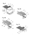
- Fig. 9 shows a plan view of the inventive device 1 with an enlarged illustrated auxiliary rake 8, which is arranged in approximately the same height as the endless conveyor 4, on the auxiliary rake 8 in the retracted position ( Fig. 9B ) and in the extended position ( Fig. 9A ), in which the upstream ends of the following, not shown here printed products 3 can be supported on the auxiliary rake 8.
- the in the Figs. 9A and 9B enlarged details also include a support member 18, on which the auxiliary rake 8 is fixed, and a slide bar 19, on which the support member 18 is slidably disposed.
- the endless conveyor (4) which has a plurality of parallel and through intermediate spaces (17) spaced from each other circulating conveyor belts (12), wherein the conveyor belts (12) are guided around the circulation elements (13).
- the in the Figs. 9, 9A and 9B shown recess 20 in the stacking shaft 5 is provided for the up and down movement of the intermediate element 7.
- Fig. 10 shows a plan view of the inventive device 1 also without the printed products to be stacked to illustrate the arrangement of the intermediate element 7 in its extended end position in the stacking shaft 5.
- the intermediate element 7 is shown in its retracted into the stacking shaft 5 end position.
- the drive units 14 for the intermediate element 7 and the auxiliary rake 8 can be seen.
Landscapes
- Engineering & Computer Science (AREA)
- Mechanical Engineering (AREA)
- Separation, Sorting, Adjustment, Or Bending Of Sheets To Be Conveyed (AREA)
- Forming Counted Batches (AREA)
- Secondary Cells (AREA)
- Pile Receivers (AREA)
Applications Claiming Priority (1)
| Application Number | Priority Date | Filing Date | Title |
|---|---|---|---|
| CH2102010 | 2010-02-19 |
Publications (2)
| Publication Number | Publication Date |
|---|---|
| EP2361865A1 true EP2361865A1 (fr) | 2011-08-31 |
| EP2361865B1 EP2361865B1 (fr) | 2015-09-16 |
Family
ID=42224603
Family Applications (1)
| Application Number | Title | Priority Date | Filing Date |
|---|---|---|---|
| EP11153779.1A Not-in-force EP2361865B1 (fr) | 2010-02-19 | 2011-02-09 | Procédé et dispositif de formation de piles à partir d'un flux de produits d'impression en formation imbriquée |
Country Status (5)
| Country | Link |
|---|---|
| US (1) | US9156646B2 (fr) |
| EP (1) | EP2361865B1 (fr) |
| JP (1) | JP2011168402A (fr) |
| CN (1) | CN102161447A (fr) |
| BR (1) | BRPI1100217A2 (fr) |
Families Citing this family (6)
| Publication number | Priority date | Publication date | Assignee | Title |
|---|---|---|---|---|
| JP5439611B1 (ja) * | 2013-01-24 | 2014-03-12 | トタニ技研工業株式会社 | シート状製品搬送装置 |
| CN105217357A (zh) * | 2013-07-26 | 2016-01-06 | 北京印刷学院 | 裱纸机的收纸装置 |
| JP6468685B2 (ja) * | 2015-03-31 | 2019-02-13 | リョービMhiグラフィックテクノロジー株式会社 | 枚葉印刷機 |
| JP6995335B2 (ja) * | 2017-06-16 | 2022-02-21 | 株式会社Isowa | カウンタエジェクタ |
| CN111070774B (zh) * | 2019-12-02 | 2025-09-09 | 中科天工技术有限公司 | 防倒上料装置及切边取模装置 |
| CN112537684A (zh) * | 2020-12-28 | 2021-03-23 | 滁州卷烟材料厂 | 一种瓦楞纸输送堆叠装置 |
Citations (6)
| Publication number | Priority date | Publication date | Assignee | Title |
|---|---|---|---|---|
| DE2725267B1 (de) * | 1977-06-03 | 1978-11-09 | Bielomatik Leuze & Co | Stapelvorrichtung zum Ablegen von Bogen |
| GB2079259A (en) * | 1980-06-23 | 1982-01-20 | Beloit Corp | Apparatus and method for the continuous collection and discharge of sheets |
| EP0718231A2 (fr) * | 1994-12-22 | 1996-06-26 | Jagenberg Papiertechnik GmbH | Dispositif pour empiler des feuilles, en particulier pour des feuilles en papier ou carton qui sont alimentées en se chevauchant |
| DE19855510A1 (de) | 1998-12-02 | 2000-06-08 | Ingo Ederer | Vorrichtung zum vertikalen Bilden von Teilstapeln von Druckprodukten |
| DE19928367A1 (de) * | 1999-06-21 | 2000-12-28 | Will E C H Gmbh & Co | Verfahren und Vorrichtung zum Wechseln von Paletten für Bogenstapel |
| DE19947329A1 (de) | 1999-10-01 | 2001-04-12 | Gramatec Grafische Maschinen T | Vorrichtung zum vertikalen Bilden von Teilstapeln von Druckereiprodukten |
Family Cites Families (18)
| Publication number | Priority date | Publication date | Assignee | Title |
|---|---|---|---|---|
| US2084741A (en) * | 1933-09-15 | 1937-06-22 | Hammermill Paper Co | Continuous automatic layboy |
| CH599025A5 (fr) * | 1976-04-23 | 1978-05-12 | Grapha Holding Ag | |
| US4290723A (en) * | 1977-06-01 | 1981-09-22 | Renholmens Mekaniska Verkstad Ab | Timber package arranger |
| US4189270A (en) * | 1978-04-24 | 1980-02-19 | Georgia-Pacific Corporation | Sheet transfer and stacking apparatus |
| US4339119A (en) * | 1979-03-13 | 1982-07-13 | Tokyo Shibaura Denki Kabushiki Kaisha | Paper sheets separating apparatus |
| DE3535113A1 (de) * | 1985-10-02 | 1987-04-23 | Jagenberg Ag | Bogenableger |
| DE4131015C2 (de) * | 1991-09-18 | 1995-10-05 | Roland Man Druckmasch | Bogenausleger |
| JPH0597317A (ja) * | 1991-10-04 | 1993-04-20 | Dainippon Ink & Chem Inc | 落下するシート状体の一時保持方法及び装置 |
| JPH05147807A (ja) | 1992-01-31 | 1993-06-15 | S K Eng Kk | シート積上げ装置 |
| DE19507370C2 (de) * | 1995-03-03 | 2003-01-09 | Heidelberger Druckmasch Ag | Bogenausleger für eine Druckmaschine |
| EP0737640B1 (fr) | 1995-04-15 | 2001-07-04 | Heidelberger Druckmaschinen Aktiengesellschaft | Procédé et dispositif pour introduire un récepteur de pile auxiliaire |
| EP0790206B1 (fr) * | 1996-02-14 | 2001-04-25 | MAN Roland Druckmaschinen AG | Procédé et dispositif de changement automatique de piles |
| US6042108A (en) * | 1997-11-26 | 2000-03-28 | Morgan; Robert A. | Zero feed interrupt sheet stacker |
| US6574943B2 (en) * | 2001-08-17 | 2003-06-10 | Blue Print Holding B.V. | Conveyor assembly for packagings, and method for delivery of a pack |
| DE10146919C1 (de) | 2001-09-24 | 2003-05-15 | Koenig & Bauer Ag | Vorrichtung zur Ausrichtung von in einer Lage übereinander angeordneten Bogen |
| DE102004062735B4 (de) * | 2004-02-19 | 2023-08-17 | Heidelberger Druckmaschinen Ag | Vorrichtung zum Ausrichten von Bogen, die auf einem Bogenstapel abgelegt werden |
| JP4150928B2 (ja) | 2004-07-08 | 2008-09-17 | 宇央 足立 | シートの処理方法及び処理装置、並びに該装置を備えたシートの加工装置 |
| DE102006028381A1 (de) * | 2006-06-19 | 2007-12-20 | E.C.H. Will Gmbh | Verfahren und Vorrichtung zur Bildung von Stapeln von Flachteilen |
-
2011
- 2011-02-09 EP EP11153779.1A patent/EP2361865B1/fr not_active Not-in-force
- 2011-02-15 US US13/027,852 patent/US9156646B2/en not_active Expired - Fee Related
- 2011-02-18 JP JP2011032851A patent/JP2011168402A/ja active Pending
- 2011-02-18 BR BRPI1100217 patent/BRPI1100217A2/pt not_active IP Right Cessation
- 2011-02-21 CN CN2011100478096A patent/CN102161447A/zh active Pending
Patent Citations (6)
| Publication number | Priority date | Publication date | Assignee | Title |
|---|---|---|---|---|
| DE2725267B1 (de) * | 1977-06-03 | 1978-11-09 | Bielomatik Leuze & Co | Stapelvorrichtung zum Ablegen von Bogen |
| GB2079259A (en) * | 1980-06-23 | 1982-01-20 | Beloit Corp | Apparatus and method for the continuous collection and discharge of sheets |
| EP0718231A2 (fr) * | 1994-12-22 | 1996-06-26 | Jagenberg Papiertechnik GmbH | Dispositif pour empiler des feuilles, en particulier pour des feuilles en papier ou carton qui sont alimentées en se chevauchant |
| DE19855510A1 (de) | 1998-12-02 | 2000-06-08 | Ingo Ederer | Vorrichtung zum vertikalen Bilden von Teilstapeln von Druckprodukten |
| DE19928367A1 (de) * | 1999-06-21 | 2000-12-28 | Will E C H Gmbh & Co | Verfahren und Vorrichtung zum Wechseln von Paletten für Bogenstapel |
| DE19947329A1 (de) | 1999-10-01 | 2001-04-12 | Gramatec Grafische Maschinen T | Vorrichtung zum vertikalen Bilden von Teilstapeln von Druckereiprodukten |
Also Published As
| Publication number | Publication date |
|---|---|
| EP2361865B1 (fr) | 2015-09-16 |
| JP2011168402A (ja) | 2011-09-01 |
| CN102161447A (zh) | 2011-08-24 |
| US9156646B2 (en) | 2015-10-13 |
| BRPI1100217A2 (pt) | 2012-09-25 |
| US20110206490A1 (en) | 2011-08-25 |
Similar Documents
| Publication | Publication Date | Title |
|---|---|---|
| EP2361865B1 (fr) | Procédé et dispositif de formation de piles à partir d'un flux de produits d'impression en formation imbriquée | |
| EP0187344A1 (fr) | Procédé et dispositif pour produire des piles individuelles composées d'une bande en accordéon | |
| DE69702274T2 (de) | Vorrichtung zum Sammeln und Stapeln von Schichtwerkstoffen, und ein Stapelverfahren | |
| WO1995009796A1 (fr) | Procede et dispositif permettant de former et de deplacer des piles de feuilles imprimees | |
| WO2014005715A1 (fr) | Dispositif et procédé de séparation de documents de valeur et système de traitement de documents de valeur | |
| EP2955135B1 (fr) | Système de transport de piles de marchandises composées de palettes comprenant des marchandises empilées et procédé de transport de piles de marchandises composées de palettes comprenant des marchandises empilées | |
| EP2810904A1 (fr) | Transport de pile de feuilles en vrac dans un canal de transport | |
| EP2581331B1 (fr) | Dispositif et procédé d'alignement de produits | |
| DE10214684A1 (de) | Fördereinrichtung und Verfahren zur Überführung von Stapeln aus Papier oder dgl. auf einen Abtransportförderer | |
| DE1280651B (de) | Stapelbildeeinrichtung fuer Papier- oder Kunststoffolienverarbeitungsmaschinen, insbesondere Sackherstellungsmaschinen | |
| DE102013100232A1 (de) | Verfahren und Vorrichtung zur Herstellung variabler Lücken zwischen Artikeln oder Artikelgruppen eines Artikelstroms | |
| EP3025994B1 (fr) | Dispositif et procédé de fabrication de paquets empilés de feuilles imprimées | |
| EP1350750B1 (fr) | Méthode et dispositif pour former des piles d'objets plats arrivant en continu | |
| EP2923975B1 (fr) | Dispositif et procédé de dépalettisation pour le prélèvement de couches à partir de paquets d'une pile de marchandises | |
| EP0644119A1 (fr) | Méthode et dispositif pour la formation des piles, en particulier des biscuits | |
| EP0514783B1 (fr) | Dispositif pour transporter des piles de feuilles en papier | |
| DE102018205944A1 (de) | Drucksystem zum Bedrucken von Substraten, Verfahren zum Betreiben des Drucksystems | |
| DE102017004232A1 (de) | Objekttransportvorrichtung | |
| CH661018A5 (de) | Verfahren und vorrichtung zum abtrennen von gruppen scheibenfoermiger gegenstaende aus einem als strom zulaufenden stapel. | |
| DE3114102A1 (de) | Verfahren und vorrichtung zum zufuehren von boegen au papier, pappe o.dgl. | |
| DE102008046125A1 (de) | Bogenverarbeitungsmaschine und Verfahren zum Ablegen von Bogen | |
| EP3984923A1 (fr) | Procédé d'alimentation en pièces allongées en bois, en matière plastique et analogues, ainsi qu'installation de mise en uvre du procédé | |
| DE4415047A1 (de) | Verfahren und Vorrichtung zum Fördern von Blattlagen aus einer Sammelstation | |
| EP0216023B1 (fr) | Dispositif pour ordonner un courant d'articles se chevauchant | |
| EP2316767A1 (fr) | Dispositif et procédé de fabrication de piles de produits d'impression |
Legal Events
| Date | Code | Title | Description |
|---|---|---|---|
| PUAI | Public reference made under article 153(3) epc to a published international application that has entered the european phase |
Free format text: ORIGINAL CODE: 0009012 |
|
| AK | Designated contracting states |
Kind code of ref document: A1 Designated state(s): AL AT BE BG CH CY CZ DE DK EE ES FI FR GB GR HR HU IE IS IT LI LT LU LV MC MK MT NL NO PL PT RO RS SE SI SK SM TR |
|
| AX | Request for extension of the european patent |
Extension state: BA ME |
|
| 17P | Request for examination filed |
Effective date: 20120220 |
|
| 17Q | First examination report despatched |
Effective date: 20121005 |
|
| GRAP | Despatch of communication of intention to grant a patent |
Free format text: ORIGINAL CODE: EPIDOSNIGR1 |
|
| INTG | Intention to grant announced |
Effective date: 20150428 |
|
| RIN1 | Information on inventor provided before grant (corrected) |
Inventor name: MAIER, PETER |
|
| GRAS | Grant fee paid |
Free format text: ORIGINAL CODE: EPIDOSNIGR3 |
|
| GRAA | (expected) grant |
Free format text: ORIGINAL CODE: 0009210 |
|
| AK | Designated contracting states |
Kind code of ref document: B1 Designated state(s): AL AT BE BG CH CY CZ DE DK EE ES FI FR GB GR HR HU IE IS IT LI LT LU LV MC MK MT NL NO PL PT RO RS SE SI SK SM TR |
|
| REG | Reference to a national code |
Ref country code: GB Ref legal event code: FG4D Free format text: NOT ENGLISH |
|
| REG | Reference to a national code |
Ref country code: CH Ref legal event code: EP |
|
| REG | Reference to a national code |
Ref country code: IE Ref legal event code: FG4D Free format text: LANGUAGE OF EP DOCUMENT: GERMAN |
|
| REG | Reference to a national code |
Ref country code: AT Ref legal event code: REF Ref document number: 749630 Country of ref document: AT Kind code of ref document: T Effective date: 20151015 |
|
| REG | Reference to a national code |
Ref country code: DE Ref legal event code: R096 Ref document number: 502011007869 Country of ref document: DE |
|
| REG | Reference to a national code |
Ref country code: NL Ref legal event code: MP Effective date: 20150916 |
|
| PG25 | Lapsed in a contracting state [announced via postgrant information from national office to epo] |
Ref country code: LV Free format text: LAPSE BECAUSE OF FAILURE TO SUBMIT A TRANSLATION OF THE DESCRIPTION OR TO PAY THE FEE WITHIN THE PRESCRIBED TIME-LIMIT Effective date: 20150916 Ref country code: GR Free format text: LAPSE BECAUSE OF FAILURE TO SUBMIT A TRANSLATION OF THE DESCRIPTION OR TO PAY THE FEE WITHIN THE PRESCRIBED TIME-LIMIT Effective date: 20151217 Ref country code: NO Free format text: LAPSE BECAUSE OF FAILURE TO SUBMIT A TRANSLATION OF THE DESCRIPTION OR TO PAY THE FEE WITHIN THE PRESCRIBED TIME-LIMIT Effective date: 20151216 Ref country code: LT Free format text: LAPSE BECAUSE OF FAILURE TO SUBMIT A TRANSLATION OF THE DESCRIPTION OR TO PAY THE FEE WITHIN THE PRESCRIBED TIME-LIMIT Effective date: 20150916 Ref country code: FI Free format text: LAPSE BECAUSE OF FAILURE TO SUBMIT A TRANSLATION OF THE DESCRIPTION OR TO PAY THE FEE WITHIN THE PRESCRIBED TIME-LIMIT Effective date: 20150916 |
|
| REG | Reference to a national code |
Ref country code: LT Ref legal event code: MG4D |
|
| PG25 | Lapsed in a contracting state [announced via postgrant information from national office to epo] |
Ref country code: RS Free format text: LAPSE BECAUSE OF FAILURE TO SUBMIT A TRANSLATION OF THE DESCRIPTION OR TO PAY THE FEE WITHIN THE PRESCRIBED TIME-LIMIT Effective date: 20150916 Ref country code: SE Free format text: LAPSE BECAUSE OF FAILURE TO SUBMIT A TRANSLATION OF THE DESCRIPTION OR TO PAY THE FEE WITHIN THE PRESCRIBED TIME-LIMIT Effective date: 20150916 Ref country code: HR Free format text: LAPSE BECAUSE OF FAILURE TO SUBMIT A TRANSLATION OF THE DESCRIPTION OR TO PAY THE FEE WITHIN THE PRESCRIBED TIME-LIMIT Effective date: 20150916 |
|
| PG25 | Lapsed in a contracting state [announced via postgrant information from national office to epo] |
Ref country code: NL Free format text: LAPSE BECAUSE OF FAILURE TO SUBMIT A TRANSLATION OF THE DESCRIPTION OR TO PAY THE FEE WITHIN THE PRESCRIBED TIME-LIMIT Effective date: 20150916 |
|
| PG25 | Lapsed in a contracting state [announced via postgrant information from national office to epo] |
Ref country code: ES Free format text: LAPSE BECAUSE OF FAILURE TO SUBMIT A TRANSLATION OF THE DESCRIPTION OR TO PAY THE FEE WITHIN THE PRESCRIBED TIME-LIMIT Effective date: 20150916 Ref country code: SK Free format text: LAPSE BECAUSE OF FAILURE TO SUBMIT A TRANSLATION OF THE DESCRIPTION OR TO PAY THE FEE WITHIN THE PRESCRIBED TIME-LIMIT Effective date: 20150916 Ref country code: CZ Free format text: LAPSE BECAUSE OF FAILURE TO SUBMIT A TRANSLATION OF THE DESCRIPTION OR TO PAY THE FEE WITHIN THE PRESCRIBED TIME-LIMIT Effective date: 20150916 Ref country code: IS Free format text: LAPSE BECAUSE OF FAILURE TO SUBMIT A TRANSLATION OF THE DESCRIPTION OR TO PAY THE FEE WITHIN THE PRESCRIBED TIME-LIMIT Effective date: 20160116 Ref country code: IT Free format text: LAPSE BECAUSE OF FAILURE TO SUBMIT A TRANSLATION OF THE DESCRIPTION OR TO PAY THE FEE WITHIN THE PRESCRIBED TIME-LIMIT Effective date: 20150916 Ref country code: EE Free format text: LAPSE BECAUSE OF FAILURE TO SUBMIT A TRANSLATION OF THE DESCRIPTION OR TO PAY THE FEE WITHIN THE PRESCRIBED TIME-LIMIT Effective date: 20150916 |
|
| PG25 | Lapsed in a contracting state [announced via postgrant information from national office to epo] |
Ref country code: RO Free format text: LAPSE BECAUSE OF FAILURE TO SUBMIT A TRANSLATION OF THE DESCRIPTION OR TO PAY THE FEE WITHIN THE PRESCRIBED TIME-LIMIT Effective date: 20150916 Ref country code: PT Free format text: LAPSE BECAUSE OF FAILURE TO SUBMIT A TRANSLATION OF THE DESCRIPTION OR TO PAY THE FEE WITHIN THE PRESCRIBED TIME-LIMIT Effective date: 20160118 Ref country code: BE Free format text: LAPSE BECAUSE OF NON-PAYMENT OF DUE FEES Effective date: 20160229 Ref country code: PL Free format text: LAPSE BECAUSE OF FAILURE TO SUBMIT A TRANSLATION OF THE DESCRIPTION OR TO PAY THE FEE WITHIN THE PRESCRIBED TIME-LIMIT Effective date: 20150916 |
|
| REG | Reference to a national code |
Ref country code: DE Ref legal event code: R097 Ref document number: 502011007869 Country of ref document: DE |
|
| PLBE | No opposition filed within time limit |
Free format text: ORIGINAL CODE: 0009261 |
|
| STAA | Information on the status of an ep patent application or granted ep patent |
Free format text: STATUS: NO OPPOSITION FILED WITHIN TIME LIMIT |
|
| 26N | No opposition filed |
Effective date: 20160617 |
|
| PG25 | Lapsed in a contracting state [announced via postgrant information from national office to epo] |
Ref country code: DK Free format text: LAPSE BECAUSE OF FAILURE TO SUBMIT A TRANSLATION OF THE DESCRIPTION OR TO PAY THE FEE WITHIN THE PRESCRIBED TIME-LIMIT Effective date: 20150916 |
|
| REG | Reference to a national code |
Ref country code: DE Ref legal event code: R119 Ref document number: 502011007869 Country of ref document: DE |
|
| PG25 | Lapsed in a contracting state [announced via postgrant information from national office to epo] |
Ref country code: LU Free format text: LAPSE BECAUSE OF FAILURE TO SUBMIT A TRANSLATION OF THE DESCRIPTION OR TO PAY THE FEE WITHIN THE PRESCRIBED TIME-LIMIT Effective date: 20160209 Ref country code: MC Free format text: LAPSE BECAUSE OF FAILURE TO SUBMIT A TRANSLATION OF THE DESCRIPTION OR TO PAY THE FEE WITHIN THE PRESCRIBED TIME-LIMIT Effective date: 20150916 |
|
| REG | Reference to a national code |
Ref country code: CH Ref legal event code: PL |
|
| GBPC | Gb: european patent ceased through non-payment of renewal fee |
Effective date: 20160209 |
|
| PG25 | Lapsed in a contracting state [announced via postgrant information from national office to epo] |
Ref country code: LI Free format text: LAPSE BECAUSE OF NON-PAYMENT OF DUE FEES Effective date: 20160229 Ref country code: CH Free format text: LAPSE BECAUSE OF NON-PAYMENT OF DUE FEES Effective date: 20160229 |
|
| REG | Reference to a national code |
Ref country code: FR Ref legal event code: ST Effective date: 20161028 |
|
| PG25 | Lapsed in a contracting state [announced via postgrant information from national office to epo] |
Ref country code: SI Free format text: LAPSE BECAUSE OF FAILURE TO SUBMIT A TRANSLATION OF THE DESCRIPTION OR TO PAY THE FEE WITHIN THE PRESCRIBED TIME-LIMIT Effective date: 20150916 |
|
| REG | Reference to a national code |
Ref country code: IE Ref legal event code: MM4A |
|
| PG25 | Lapsed in a contracting state [announced via postgrant information from national office to epo] |
Ref country code: DE Free format text: LAPSE BECAUSE OF NON-PAYMENT OF DUE FEES Effective date: 20160901 Ref country code: GB Free format text: LAPSE BECAUSE OF NON-PAYMENT OF DUE FEES Effective date: 20160209 Ref country code: IE Free format text: LAPSE BECAUSE OF NON-PAYMENT OF DUE FEES Effective date: 20160209 Ref country code: FR Free format text: LAPSE BECAUSE OF NON-PAYMENT OF DUE FEES Effective date: 20160229 |
|
| REG | Reference to a national code |
Ref country code: AT Ref legal event code: MM01 Ref document number: 749630 Country of ref document: AT Kind code of ref document: T Effective date: 20160209 |
|
| PG25 | Lapsed in a contracting state [announced via postgrant information from national office to epo] |
Ref country code: AT Free format text: LAPSE BECAUSE OF NON-PAYMENT OF DUE FEES Effective date: 20160209 |
|
| PG25 | Lapsed in a contracting state [announced via postgrant information from national office to epo] |
Ref country code: MT Free format text: LAPSE BECAUSE OF FAILURE TO SUBMIT A TRANSLATION OF THE DESCRIPTION OR TO PAY THE FEE WITHIN THE PRESCRIBED TIME-LIMIT Effective date: 20150916 |
|
| PG25 | Lapsed in a contracting state [announced via postgrant information from national office to epo] |
Ref country code: HU Free format text: LAPSE BECAUSE OF FAILURE TO SUBMIT A TRANSLATION OF THE DESCRIPTION OR TO PAY THE FEE WITHIN THE PRESCRIBED TIME-LIMIT; INVALID AB INITIO Effective date: 20110209 Ref country code: SM Free format text: LAPSE BECAUSE OF FAILURE TO SUBMIT A TRANSLATION OF THE DESCRIPTION OR TO PAY THE FEE WITHIN THE PRESCRIBED TIME-LIMIT Effective date: 20150916 Ref country code: CY Free format text: LAPSE BECAUSE OF FAILURE TO SUBMIT A TRANSLATION OF THE DESCRIPTION OR TO PAY THE FEE WITHIN THE PRESCRIBED TIME-LIMIT Effective date: 20150916 |
|
| PG25 | Lapsed in a contracting state [announced via postgrant information from national office to epo] |
Ref country code: TR Free format text: LAPSE BECAUSE OF FAILURE TO SUBMIT A TRANSLATION OF THE DESCRIPTION OR TO PAY THE FEE WITHIN THE PRESCRIBED TIME-LIMIT Effective date: 20150916 Ref country code: MK Free format text: LAPSE BECAUSE OF FAILURE TO SUBMIT A TRANSLATION OF THE DESCRIPTION OR TO PAY THE FEE WITHIN THE PRESCRIBED TIME-LIMIT Effective date: 20150916 |
|
| PG25 | Lapsed in a contracting state [announced via postgrant information from national office to epo] |
Ref country code: BG Free format text: LAPSE BECAUSE OF FAILURE TO SUBMIT A TRANSLATION OF THE DESCRIPTION OR TO PAY THE FEE WITHIN THE PRESCRIBED TIME-LIMIT Effective date: 20150916 |
|
| PG25 | Lapsed in a contracting state [announced via postgrant information from national office to epo] |
Ref country code: AL Free format text: LAPSE BECAUSE OF FAILURE TO SUBMIT A TRANSLATION OF THE DESCRIPTION OR TO PAY THE FEE WITHIN THE PRESCRIBED TIME-LIMIT Effective date: 20150916 |