EP2362017A2 - Elément de liaison et agencement doté d'un élément de liaison - Google Patents
Elément de liaison et agencement doté d'un élément de liaison Download PDFInfo
- Publication number
- EP2362017A2 EP2362017A2 EP11001415A EP11001415A EP2362017A2 EP 2362017 A2 EP2362017 A2 EP 2362017A2 EP 11001415 A EP11001415 A EP 11001415A EP 11001415 A EP11001415 A EP 11001415A EP 2362017 A2 EP2362017 A2 EP 2362017A2
- Authority
- EP
- European Patent Office
- Prior art keywords
- nut
- rail part
- threaded
- threaded bolt
- insert
- Prior art date
- Legal status (The legal status is an assumption and is not a legal conclusion. Google has not performed a legal analysis and makes no representation as to the accuracy of the status listed.)
- Granted
Links
- 238000005553 drilling Methods 0.000 claims description 5
- 238000003754 machining Methods 0.000 claims description 5
- 230000001681 protective effect Effects 0.000 description 5
- 238000007789 sealing Methods 0.000 description 4
- 230000005540 biological transmission Effects 0.000 description 3
- 238000012423 maintenance Methods 0.000 description 3
- 230000035515 penetration Effects 0.000 description 3
- 239000000758 substrate Substances 0.000 description 3
- 241000269350 Anura Species 0.000 description 2
- 238000010276 construction Methods 0.000 description 2
- 238000013461 design Methods 0.000 description 2
- 239000011343 solid material Substances 0.000 description 2
- XLYOFNOQVPJJNP-UHFFFAOYSA-N water Substances O XLYOFNOQVPJJNP-UHFFFAOYSA-N 0.000 description 2
- 238000003466 welding Methods 0.000 description 2
- 229910000975 Carbon steel Inorganic materials 0.000 description 1
- 206010038743 Restlessness Diseases 0.000 description 1
- 229910000831 Steel Inorganic materials 0.000 description 1
- 229910000746 Structural steel Inorganic materials 0.000 description 1
- 230000002411 adverse Effects 0.000 description 1
- 238000013459 approach Methods 0.000 description 1
- 230000000903 blocking effect Effects 0.000 description 1
- 239000010962 carbon steel Substances 0.000 description 1
- 239000000356 contaminant Substances 0.000 description 1
- 238000011109 contamination Methods 0.000 description 1
- 230000008021 deposition Effects 0.000 description 1
- 238000011161 development Methods 0.000 description 1
- 230000000422 nocturnal effect Effects 0.000 description 1
- 230000036961 partial effect Effects 0.000 description 1
- 238000012805 post-processing Methods 0.000 description 1
- 230000002829 reductive effect Effects 0.000 description 1
- 230000000284 resting effect Effects 0.000 description 1
- 150000003839 salts Chemical class 0.000 description 1
- 238000000926 separation method Methods 0.000 description 1
- 239000010959 steel Substances 0.000 description 1
- 239000000126 substance Substances 0.000 description 1
Images


Classifications
-
- E—FIXED CONSTRUCTIONS
- E01—CONSTRUCTION OF ROADS, RAILWAYS, OR BRIDGES
- E01B—PERMANENT WAY; PERMANENT-WAY TOOLS; MACHINES FOR MAKING RAILWAYS OF ALL KINDS
- E01B7/00—Switches; Crossings
- E01B7/10—Frogs
- E01B7/12—Fixed frogs made of one part or composite
-
- F—MECHANICAL ENGINEERING; LIGHTING; HEATING; WEAPONS; BLASTING
- F16—ENGINEERING ELEMENTS AND UNITS; GENERAL MEASURES FOR PRODUCING AND MAINTAINING EFFECTIVE FUNCTIONING OF MACHINES OR INSTALLATIONS; THERMAL INSULATION IN GENERAL
- F16B—DEVICES FOR FASTENING OR SECURING CONSTRUCTIONAL ELEMENTS OR MACHINE PARTS TOGETHER, e.g. NAILS, BOLTS, CIRCLIPS, CLAMPS, CLIPS OR WEDGES; JOINTS OR JOINTING
- F16B5/00—Joining sheets or plates, e.g. panels, to one another or to strips or bars parallel to them
- F16B5/02—Joining sheets or plates, e.g. panels, to one another or to strips or bars parallel to them by means of fastening members using screw-thread
- F16B5/0275—Joining sheets or plates, e.g. panels, to one another or to strips or bars parallel to them by means of fastening members using screw-thread the screw-threaded element having at least two axially separated threaded portions
-
- F—MECHANICAL ENGINEERING; LIGHTING; HEATING; WEAPONS; BLASTING
- F16—ENGINEERING ELEMENTS AND UNITS; GENERAL MEASURES FOR PRODUCING AND MAINTAINING EFFECTIVE FUNCTIONING OF MACHINES OR INSTALLATIONS; THERMAL INSULATION IN GENERAL
- F16B—DEVICES FOR FASTENING OR SECURING CONSTRUCTIONAL ELEMENTS OR MACHINE PARTS TOGETHER, e.g. NAILS, BOLTS, CIRCLIPS, CLAMPS, CLIPS OR WEDGES; JOINTS OR JOINTING
- F16B37/00—Nuts or like thread-engaging members
- F16B37/14—Cap nuts; Nut caps or bolt caps
- F16B37/145—Sleeve nuts, e.g. combined with bolts
-
- F—MECHANICAL ENGINEERING; LIGHTING; HEATING; WEAPONS; BLASTING
- F16—ENGINEERING ELEMENTS AND UNITS; GENERAL MEASURES FOR PRODUCING AND MAINTAINING EFFECTIVE FUNCTIONING OF MACHINES OR INSTALLATIONS; THERMAL INSULATION IN GENERAL
- F16B—DEVICES FOR FASTENING OR SECURING CONSTRUCTIONAL ELEMENTS OR MACHINE PARTS TOGETHER, e.g. NAILS, BOLTS, CIRCLIPS, CLAMPS, CLIPS OR WEDGES; JOINTS OR JOINTING
- F16B41/00—Measures against loss of bolts, nuts, or pins; Measures against unauthorised operation of bolts, nuts or pins
- F16B41/005—Measures against unauthorised operation of bolts, nuts or pins
Definitions
- the invention relates to an arrangement with a rail part fastened to at least one connecting element on a base section.
- the present invention relates to an arrangement with an insert which can be interchangeably fixed to at least one connecting element on a switch frog base body, furthermore, in particular, from highly wear-resistant special structural steel with very good weldability.
- the present invention relates to a connecting element designed for fastening a rail part to a base section and, preferably, for lifting the rail part from the underground section, in particular for fastening and / or lifting a switch part, more particularly a replaceable insert in a switch frog.
- the protective box has a relatively large amount of space.
- the connection of the inputs or attachments with the heart piece body about the arranged in the protective box brackets structurally complex.
- To replace the inserts it is necessary to open the protective box from above and to release the brackets. Below the insert are for this purpose bevels on which tools are attached, so that the insert can be pushed upwards.
- Object of the present invention is to provide a connecting element and an arrangement of the type mentioned above, with which it is possible in a simple manner, a rail part, in particular an insert for a Weichenhoulder, on a background section, in particular on a heart piece body of Centerpiece, to attach.
- a rail part in particular an insert for a Weichenhoulder
- a background section in particular on a heart piece body of Centerpiece
- the rail part should be easy on the subsurface section or be lifted.
- the connection between the rail part and the ground section should be structurally simple and low maintenance.
- the connection between the rail part and the underground section should be characterized by a small footprint.
- a threaded bolt and a nut are provided in a connecting element, wherein the threaded bolt has at one end a first threaded portion for screwing into the base portion and at the other end a second threaded portion for the nut, wherein the nut after placing the rail portion on the substrate portion can be screwed from above through a hole in the rail part on the second threaded portion to brace the rail member relative to the ground.
- the threaded bolt can have a greater extent in the radial direction in the region of the lifting portion than in the area of the second threaded portion.
- the arrangement according to the invention accordingly has a rail part with at least one (radial) stop surface acting in the axial direction for the lifting section of the threaded bolt, so that it is possible to lift the rail part relative to the underground section by unscrewing the threaded bolt from the underground section.
- the rail part is preferably located exclusively on the underground section and is thus clamped between the nut and the underground section.
- unscrewing the threaded bolt then enters the lifting portion of the threaded bolt with a stop surface on the rail part in contact, so that a positive connection is formed in the axial direction, which in a further unscrewing of the threaded bolt for attachment or, lifting the rail part of the underground section results, are in a simple manner, attachment of the rail part with the underground portion and also the subsequent lifting of the rail part of the underground section for maintenance or replacement of the rail part possible.
- a threaded bolt and a nut can be provided in a connecting element of the type mentioned, wherein the threaded bolt has at one end a first threaded portion for screwing into the base portion and at the other end a second threaded portion for the mother, wherein the Nut after placing the rail member on the Untergnmdabêt from above through a hole in the rail part on the second threaded portion can be screwed to brace the rail member relative to the ground, the nut on the outer end face an engaging portion for a tool for screwing onto the second threaded portion , wherein the second threaded portion has an upper engagement portion for a tool for unscrewing the threaded bolt and for lifting the rail member relative to the ground and wherein the nut the upper engagement portion of the threaded bolt after the Unscrew the second threaded portion of the threaded bolt over the entire surface covered.
- the connecting element is formed by a threaded bolt and a cap nut, which is screwe
- the nut can be easily screwed onto the threaded bolt in a mounting state, wherein the torque required for tightening the nut is applied via the engaging portion of the nut.
- the attacking section is separated from the mother.
- the attacking section can be separated from the mother by breaking off or by machining.
- the engagement section is screwed (releasably) to the nut.
- the nut after disconnecting or releasing the engagement section in the attachment state, the nut can have a substantially planar outside end face, which is advantageous in particular when the nut is being driven over in the operating state is and leads to a uniform surface pressure in the region of the outer end face of the mother.
- the connecting element according to the invention can in principle be used for fastening any rail parts to a substrate
- the invention preferably relates to a connecting element for fastening inserts or attachments for switch frogs, which are connected to a frog base body as a base portion.
- the engaging portion of the nut may basically have any shape that allows the attachment of a tool for unscrewing the nut on the upper threaded portion of the threaded bolt.
- the engagement portion is formed by an axially projecting beyond an outer end face of the nut projection.
- the extension may have at its free end an inner or outer hexagonal section for the tool.
- the nut may have a closed outer end face, so that the nut in the fastening state, the hole in the rail part substantially full surface closes, which prevents the ingress of dirt or contaminants in the region of the bore.
- the outer end face of the nut in the attachment state, d. H. after screwing on the threaded bolt and the bracing of the rail part, at least at the edge is aligned with an outer surface of the rail part. The result is an outwardly closed surface in the region of the connection of the rail part with the underground section. As a result, the penetration of foreign and foreign matter into the bore is largely prevented.
- a predetermined breaking point may be provided, so that the engaging portion can be released in a simple manner by breaking off the nut.
- the attacking section is separated by machining from the mother.
- the engagement section is screwed to the nut is.
- the connection between the engaging portion and the nut must have sufficient strength to ensure the transmission of a sufficiently large torque when screwing the nut on the threaded bolt and the bracing of the rail part.
- the second threaded portion preferably has an upper engagement portion for a tool for unscrewing the threaded bolt and, preferably, for lifting the rail member relative to the ground.
- the threaded bolt can be unscrew with a tool in a simple manner and with little effort from the underground section. If the threaded bolt has a lifting section, it comes into contact with the overlying rail part when the threaded bolt is unscrewed, resulting in further lifting of the threaded bolt from the underground section for lifting the rail part. As a result, the replacement of the rail part is simplified.
- a further lower engaging portion may be provided for a tool, so that it is also possible in principle to unscrew the threaded bolt from below from the base portion via a corresponding opening in the underground section.
- the nut may in this context be made of a solid material and having an internal bore with an internal thread for the second threaded portion of the threaded bolt.
- the inner bore extends from an inner or lower end face of the mother, starting in the axial direction upwards, but does not pass through the mother completely, so that in the upper edge region of the mother remains a closed section of a solid material.
- the nut may have a through opening in a disassembled condition, the opening being formed by a first upper bore portion extending inwardly from an outer end face of the nut and a second lower extending from the inner end face of the nut to the first bore portion A borehole section, wherein the first borehole section has a larger diameter than the second borehole section and the second borehole section has an internal thread for the second threaded section of the threaded bolt.
- the second threaded portion of the threaded bolt then engages in the first borehole section, so that it is possible in a simple manner to attach a tool from above over the first borehole section to the upper engagement section of the threaded bolt and unscrew the threaded bolt.
- the nut can also already have a through opening of the type described above in the fastening state, that is to say, prior to drilling from above, in which case a cover or cap can be provided which can be externally connected to the nut by means of a screw connection or latching or clamping connection is connected.
- the cover or cap may have an engagement portion for a tool for screwing the nut.
- a (further) Angrzffsabterrorism be provided on the cap or the cover to unscrew or remove the cap or cover of the mother can. After releasing the connection between the cap or the cover and the nut then access from the outside to the engaging portion of the threaded bolt is possible over the first borehole section.
- a (further) attack section for example, a slot or hexagonal depression in the cap or the cover can be provided.
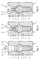
- Fig. 1 to 4 is an assembly 1 with a connecting element for attachment of an insert 2 shown only schematically or essay for a Weichenhoulder on a heart piece main body 3 shown as background section.
- the connecting element for lifting the insert 2 is formed by the heart base body 3. It is understood that the connecting element can in principle also be provided for the attachment of any rail parts to a subgrade.
- the connecting element has a threaded bolt 4 and a nut 5.
- the threaded bolt 4 has at a lower end a first threaded portion 6 for screwing into the heart piece main body 3 and at the other upper end a second threaded portion 7 for the nut 5.
- the nut 5 can be screwed from above through a hole 8 in the insert 2 onto the second threaded portion 7 which partially passes through the insert 2.
- the insert 2 is tensioned relative to the centerpiece main body 3 or fastened to the centerpiece 3.
- a borehole 9 is provided with an internally threaded portion into which the threaded bolt 4 with the first threaded portion 6 can be screwed.
- the threaded bolt 4 has a central lifting section 10, which in the illustrated embodiment is lowered in half into a corresponding widening of the borehole 9 at the top of the frog base body 3.
- a free space 11 is provided in the clamped state or in the operating state of the insert 2 in the clamped state or in the operating state of the insert 2 in the clamped state or in the operating state of the insert 2 in the clamped state or in the operating state of the insert 2 is substantially the entire surface only on the heart piece main body 3, wherein between the insert 2 and the lifting portion 10, a free space 11 is provided.
- an upper end face 12 of the lifting section 10 comes into contact with a shoulder 13 of the insert 2, resulting in further unscrewing of the threaded bolt 10 for lifting the insert 2 from the frog base body 3.
- An inner contact surface 13a on the shoulder 13 cooperates with an area near the edge of the lifting section 10.
- the shoulder 13 is replaced by a corresponding diameter extension of the bore 8 on the inner End face of the insert 2 formed.
- the in Fig. 2 is shown, approximately the upper half of the lifting portion 10 is received in the bore 8 in the region of the diameter extension.
- the insert 2 is preferably not located on the upper end face 12 of the threaded bolt 4, but only on the heart piece main body 3.
- FIG. 1 shows, the nut 5 in an assembled state on the top 14 an engaging portion 15 for a tool for transmitting a sufficiently large torque when screwing the nut 5 on the second threaded portion 7, wherein the engaging portion 15 is detachably connected to the nut 5.
- the engagement portion 15 is formed by an extension on the nut 5, wherein the engagement portion 15 projects in the axial direction via an outer end face 16 of the nut.
- a tool can be put on the trained as a hexagon attack section 15 in a simple manner.
- the engagement portion 15 is connected via a web-shaped shaft shoulder 17 with the nut 5, it being understood that the shaft shoulder 17 has a sufficient rotational strength to ensure the transmission of sufficient clamping force when screwing the nut 5 on the upper threaded portion 7.
- the attack section 15 can be separated by breaking off the nut 5.
- a predetermined breaking point in the connecting region of the engaging portion 15 may be provided with the outer end face 16 of the nut 5.
- a machining post-processing of the predetermined breaking point can be provided.
- the outer end face 16 of the nut 5 is aligned in the attached state, at least at the edge side with an outer surface 18 of the insert 2.
- the outer end face 16 may be slightly curved outward or lie substantially in the plane of the outer surface 18.
- the nut 5 has a closed surface in the assembly and operating state. As a result, an engaging portion 19 is protected on the threaded bolt 4 against contamination or damage.
- the engagement portion 19 on the second threaded portion 7 is designed for unscrewing the threaded bolt 4 with a corresponding tool and, preferably, for lifting the insert 2 relative to the heart piece main body 3.
- the engaging portion 19 may be formed as an external hexagon. About the hexagon socket can apply the loosening moment.
- a borehole 21 is lowered starting from the upper side 14 so deeply into the nut 5 until the engagement section 19 is exposed.
- a ring drill can be used to widen a bore 20 which has an internal thread for the upper threaded portion 7 of the threaded bolt 4 in the lower region.
- Fig. 3 the nut 5 is shown after drilling. It is now possible in a simple manner, from the top or outside to attach a tool on the attack section 19 to unscrew the threaded bolt 4 from the heart piece main body 3 and thus to raise the insert 2 from the heart piece main body 3.
- the nut has an upper cone portion 22, so that the transmission of the required clamping force and the centering of the nut 5 in the borehole 8 as well as a sufficient seal of the borehole 8 with respect to the environment are equally ensured.
- sealing means 23 are provided to provide sealing surfaces to the insert 2 and to the frog body 3, so that the ingress of water, de-icing salt and the like is prevented. This allows a problem-free release of the connecting element even after a longer period of use.
- the lifting section 10 is located after a complete screwing with a lower end face 24 on a shoulder 25 of the heart piece main body 3, which contributes to a secure support on the heart piece main body 3.
- the lower threaded portion 6 may have a further engagement portion 26, which may also be formed as an external hexagon.
- a further engagement portion 26 which may also be formed as an external hexagon.
- the threaded bolt 4 can have a fine thread at the top and a standard thread at the bottom.
- FIG. 5 to 7 a further embodiment of an arrangement 1 for fastening an insert 2 for a point frog piece on a heart piece main body 3 is shown.
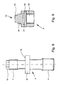
- Fig. 8 is a threaded bolt 4 in the Fig. 5 to 7 illustrated arrangement 1 and in Fig. 9 a fastening nut 5 for the threaded bolt 4 Fig. 8 shown.
- the same reference numerals are used for the same or similar parts. This is intended to indicate that corresponding or comparable properties and advantages are achieved, even if a repeated description of these parts is omitted. In the following, only the differences of the illustrated arrangements 1 will be discussed in more detail.
- the threaded bolt 4 is shown as a system screw with its lower end in the block-like heart piece main body 3 screwed in to the lifting section 10 and lies in the region of the lifting section 10 on the heart piece main body 3, wherein the lifting section 10 in contrast to the in the Fig. 1 to 4
- arrangement 1 shown is not lowered into the heart piece main body 3.
- the underside of the lifting section 10 acts as a bearing seat for the threaded bolt 4.
- the core insert 2 has a through hole 8 for the upper part of the threaded bolt 4, wherein the bore 8 has a first diameter extension in the upper region starting from an upper side 18 of the insert 2 and a second diameter enlargement in the lower region starting from a lower side 26 of the insert 2 having.
- annular shoulders 13 and 27 are formed on the insert 2.
- a cap nut 5 is screwed onto the threaded bolt 4 from above after placing the insert 2 on the heart piece main body 3 until it comes into abutment against the upper shoulder 27 of the insert 2 and further Unscrew the insert 2 clamped against the heart piece main body 3.
- a permanent attachment of the insert 2 is ensured.
- the height of the lifting portion 10 is less than the depth of the borehole 8 in the region of the lower second diameter extension. This ensures that it can come at any time to a resting of the insert 2 on the lifting portion 10 of the threaded bolt 4.
- O-rings are provided as sealing means 23 against water penetration.
- Fig. 9 shows, the cap nut 5 in the mounted state on the top 14 on a central pin 28 as a key approach with an engaging portion 15, wherein the engaging portion 15 may be formed as a hexagon.
- the nut 5 also has a bore 20 with an internally threaded portion, which allows the screwing onto the threaded portion 7 of the threaded bolt 4.
- the outer diameter of the nut 5 is smaller than the inner diameter of the bore 8 in the region of the upper first diameter extension of the insert 2, which allows the simple screwing of the nut 5 on the threaded bolt 4.
- the nut 5 then bears against the upper shoulder 27 of the insert 2 from above, as a result of which the insert 2 is braced against the centerpiece main body 3 by the threaded bolt 4 screwed into the core piece body 3.
- Fig. 6 results in the cap nut 5 can be aligned in the attachment state after the execution of the pin 28 with the insert 2, so that the cap nut 5 and the upper edge of the insert 2 form a flat surface.
- the height of the nut is accordingly adapted to the depth of the borehole in the insert 2 until reaching the upper shoulder 27.
- the bore 20 of the nut 5 has an enlarged diameter at the upper end, so that it is possible to dismantle the threaded bolt 4 after cutting the pin 28 by machining the nut 5 in a simple manner, in the nut 5 starting from the top 14 a Introduce core hole and then attach a socket wrench as a tool on a trained example as a hexagon attack section 19 on the screw head of the threaded bolt 4 to unscrew the threaded bolt 4 from the heart piece main body 3 and thus lift the insert 2 from the heart piece main body 3.
- a socket wrench as a tool on a trained example as a hexagon attack section 19 on the screw head of the threaded bolt 4 to unscrew the threaded bolt 4 from the heart piece main body 3 and thus lift the insert 2 from the heart piece main body 3.
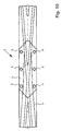
- a heart piece main body 3 is shown with an interchangeable screwed from above insert 2, which form an assembly 1.
- the core body 3 consists of a continuously forged block made of a carbon steel.
- the replaceable insert 2 consists of highly wear-resistant special steel with very good weldability and a strength of preferably about 1200 to 1300 MPa and / or a hardness at room temperature of preferably about 400 HBW (according to DIN EN ISO 6506).
- the insert 2 has on the upper side incorporated driving and guiding grooves.
- the insert 2 is designed so that it is interchangeable from above. For this, the above based on the Fig. 1 to 9 used described connecting elements.
- the fastening system described ensures that the forces occurring during the over-travel are introduced directly into the heart piece main body 3.
- the core construction ensures high wear resistance in the overflow area and can preferably be used in highly stressed areas.
- the insert 2 is attached to the heart stucco body 3 via six connecting elements, which are shown in the attached state.
- the nuts 5 (after the separation of the engaging portions 15) and the insert 2 form a uniform surface.
- a core bore is introduced from the outside into each nut 5 in the middle, in order to be able to unscrew the threaded bolts 4 from the centerpiece main body 3 with a socket wrench and thus lift the insert 2 from the centerpiece main body 3, which considerably simplifies the exchange.
Landscapes
- Engineering & Computer Science (AREA)
- Mechanical Engineering (AREA)
- General Engineering & Computer Science (AREA)
- Architecture (AREA)
- Civil Engineering (AREA)
- Structural Engineering (AREA)
- Switch Cases, Indication, And Locking (AREA)
- Railway Tracks (AREA)
- Joining Of Building Structures In Genera (AREA)
- Dowels (AREA)
- Earth Drilling (AREA)
- Connection Of Plates (AREA)
Applications Claiming Priority (2)
| Application Number | Priority Date | Filing Date | Title |
|---|---|---|---|
| DE102010008708 | 2010-02-19 | ||
| DE102010015235.8A DE102010015235B4 (de) | 2010-02-19 | 2010-04-15 | Anordnung mit einem über ein Verbindungselement an einem Herzstückgrundkörper eines Weichenherzstücks befestigten Einsatz und Verbindungselement |
Publications (3)
| Publication Number | Publication Date |
|---|---|
| EP2362017A2 true EP2362017A2 (fr) | 2011-08-31 |
| EP2362017A3 EP2362017A3 (fr) | 2013-02-13 |
| EP2362017B1 EP2362017B1 (fr) | 2016-03-30 |
Family
ID=44069891
Family Applications (1)
| Application Number | Title | Priority Date | Filing Date |
|---|---|---|---|
| EP11001415.6A Active EP2362017B1 (fr) | 2010-02-19 | 2011-02-21 | Elément de liaison et agencement doté d'un élément de liaison |
Country Status (2)
| Country | Link |
|---|---|
| EP (1) | EP2362017B1 (fr) |
| DE (1) | DE102010015235B4 (fr) |
Family Cites Families (7)
| Publication number | Priority date | Publication date | Assignee | Title |
|---|---|---|---|---|
| GB191107781A (en) * | 1911-03-28 | 1912-03-28 | Chessborough Mackenzie-Kennedy | Improvements in Bolts and Nuts. |
| DE10311113A1 (de) * | 2003-03-12 | 2004-09-23 | Bwg Gmbh & Co. Kg | Rillenschienenherzstück |
| DE10326005A1 (de) * | 2003-06-10 | 2004-12-30 | Volkswagen Ag | Abreißmutter |
| DE202004010655U1 (de) * | 2004-07-07 | 2004-09-09 | Thyssenkrupp Weichenbau Gmbh | Rillenschienen-Herzstück |
| US20070051851A1 (en) * | 2005-09-02 | 2007-03-08 | The Boeing Company | Multi-piece fastener for limited clearance applications |
| DE102007037751A1 (de) * | 2007-08-10 | 2009-02-19 | Vossloh-Werke Gmbh | System zum Befestigen einer Schiene für ein Schienenfahrzeug auf einem festen Untergrund |
| CZ18503U1 (cs) * | 2008-03-18 | 2008-04-28 | DT- Výhybkárna a strojírna a. s. | Srdcovka |
-
2010
- 2010-04-15 DE DE102010015235.8A patent/DE102010015235B4/de not_active Expired - Fee Related
-
2011
- 2011-02-21 EP EP11001415.6A patent/EP2362017B1/fr active Active
Non-Patent Citations (1)
| Title |
|---|
| None |
Also Published As
| Publication number | Publication date |
|---|---|
| EP2362017B1 (fr) | 2016-03-30 |
| DE102010015235B4 (de) | 2017-02-09 |
| EP2362017A3 (fr) | 2013-02-13 |
| DE102010015235A1 (de) | 2011-08-25 |
Similar Documents
| Publication | Publication Date | Title |
|---|---|---|
| DE102009006520B4 (de) | Mechanisches Spannelement und Spannsystem | |
| DE102010051048A1 (de) | Wechselhaltersystem für einen Meißel | |
| EP3032093B1 (fr) | Dispositif de fixation d'une pale de rotor sur un moyeu de rotor d'une éolienne | |
| DE102012104298B4 (de) | Werkzeug | |
| DE102007063199A1 (de) | Werkzeug für die spanende Bearbeitung, insbesondere Langdrehwerkzeug | |
| DE102014103657B4 (de) | Brechwerkzeug | |
| EP2465627A1 (fr) | Outil de forage | |
| DE202019104561U1 (de) | Sperrscheibe | |
| EP2362017B1 (fr) | Elément de liaison et agencement doté d'un élément de liaison | |
| DE202011004123U1 (de) | Teilbare Spindelwelle | |
| DE102005052419B4 (de) | Schraubverbindung | |
| CH700315B1 (de) | Spannsystem mit einem Spannelement und einem Schlüssel zum Anziehen des Spannelements. | |
| EP3567264A1 (fr) | Système de fixation | |
| EP4079673B1 (fr) | Dispositif de soulèvement pour le système d'ancrage de transport à filetage | |
| EP3479961A1 (fr) | Vis de fixation amovible des objets accessibles au public, outil de vissage et mobilier urbain | |
| EP1331066B1 (fr) | Clé de serrage d'un dispositif de fixation anti-vol d'une roue de véhicule à un moyeu de roue | |
| DE4034445B4 (de) | Schraubelement mit selbstsicherndem Gewinde | |
| EP2633959B1 (fr) | Dispositif de fixation sécurisée d'un manche en bois dans l'emmanchure d'une tête de marteau ainsi qu'une vis destinée à la fixation d'un manche en bois dans l'emmanchure d'une tête de marteau | |
| DE202010013057U1 (de) | Meißelhalter und Werkzeugunterteil für einen Meißelhalter | |
| DE202015106961U1 (de) | Werkzeug | |
| EP2236843B1 (fr) | Agencement composé d'une vis ainsi que d'une sécurité anti-perte fixée sur la vis | |
| DE2827911A1 (de) | Diebstahlsicherung fuer kraftfahrzeug-kennzeichenschilder | |
| DE3807918A1 (de) | Sicherheitsschraube | |
| DE202011000915U1 (de) | Spaltmutter | |
| EP3227495B1 (fr) | Joint de chaussee avec elements a peigne |
Legal Events
| Date | Code | Title | Description |
|---|---|---|---|
| PUAI | Public reference made under article 153(3) epc to a published international application that has entered the european phase |
Free format text: ORIGINAL CODE: 0009012 |
|
| AK | Designated contracting states |
Kind code of ref document: A2 Designated state(s): AL AT BE BG CH CY CZ DE DK EE ES FI FR GB GR HR HU IE IS IT LI LT LU LV MC MK MT NL NO PL PT RO RS SE SI SK SM TR |
|
| AX | Request for extension of the european patent |
Extension state: BA ME |
|
| PUAL | Search report despatched |
Free format text: ORIGINAL CODE: 0009013 |
|
| AK | Designated contracting states |
Kind code of ref document: A3 Designated state(s): AL AT BE BG CH CY CZ DE DK EE ES FI FR GB GR HR HU IE IS IT LI LT LU LV MC MK MT NL NO PL PT RO RS SE SI SK SM TR |
|
| AX | Request for extension of the european patent |
Extension state: BA ME |
|
| RIC1 | Information provided on ipc code assigned before grant |
Ipc: E01B 7/12 20060101AFI20130107BHEP Ipc: F16B 5/02 20060101ALI20130107BHEP |
|
| 17P | Request for examination filed |
Effective date: 20130806 |
|
| RBV | Designated contracting states (corrected) |
Designated state(s): AL AT BE BG CH CY CZ DE DK EE ES FI FR GB GR HR HU IE IS IT LI LT LU LV MC MK MT NL NO PL PT RO RS SE SI SK SM TR |
|
| 17Q | First examination report despatched |
Effective date: 20140305 |
|
| RAP1 | Party data changed (applicant data changed or rights of an application transferred) |
Owner name: KUENSTLER BAHNTECHNIK GMBH Owner name: HEINRICH KRUG GMBH & CO. KG Owner name: RIECKEN MASCHINENBAU GMBH |
|
| GRAP | Despatch of communication of intention to grant a patent |
Free format text: ORIGINAL CODE: EPIDOSNIGR1 |
|
| INTG | Intention to grant announced |
Effective date: 20150806 |
|
| GRAS | Grant fee paid |
Free format text: ORIGINAL CODE: EPIDOSNIGR3 |
|
| GRAA | (expected) grant |
Free format text: ORIGINAL CODE: 0009210 |
|
| AK | Designated contracting states |
Kind code of ref document: B1 Designated state(s): AL AT BE BG CH CY CZ DE DK EE ES FI FR GB GR HR HU IE IS IT LI LT LU LV MC MK MT NL NO PL PT RO RS SE SI SK SM TR |
|
| REG | Reference to a national code |
Ref country code: GB Ref legal event code: FG4D Free format text: NOT ENGLISH |
|
| REG | Reference to a national code |
Ref country code: CH Ref legal event code: EP |
|
| REG | Reference to a national code |
Ref country code: AT Ref legal event code: REF Ref document number: 785543 Country of ref document: AT Kind code of ref document: T Effective date: 20160415 |
|
| REG | Reference to a national code |
Ref country code: IE Ref legal event code: FG4D Free format text: LANGUAGE OF EP DOCUMENT: GERMAN |
|
| REG | Reference to a national code |
Ref country code: DE Ref legal event code: R096 Ref document number: 502011009205 Country of ref document: DE |
|
| REG | Reference to a national code |
Ref country code: LT Ref legal event code: MG4D |
|
| PG25 | Lapsed in a contracting state [announced via postgrant information from national office to epo] |
Ref country code: GR Free format text: LAPSE BECAUSE OF FAILURE TO SUBMIT A TRANSLATION OF THE DESCRIPTION OR TO PAY THE FEE WITHIN THE PRESCRIBED TIME-LIMIT Effective date: 20160701 Ref country code: FI Free format text: LAPSE BECAUSE OF FAILURE TO SUBMIT A TRANSLATION OF THE DESCRIPTION OR TO PAY THE FEE WITHIN THE PRESCRIBED TIME-LIMIT Effective date: 20160330 Ref country code: NO Free format text: LAPSE BECAUSE OF FAILURE TO SUBMIT A TRANSLATION OF THE DESCRIPTION OR TO PAY THE FEE WITHIN THE PRESCRIBED TIME-LIMIT Effective date: 20160630 Ref country code: HR Free format text: LAPSE BECAUSE OF FAILURE TO SUBMIT A TRANSLATION OF THE DESCRIPTION OR TO PAY THE FEE WITHIN THE PRESCRIBED TIME-LIMIT Effective date: 20160330 |
|
| REG | Reference to a national code |
Ref country code: NL Ref legal event code: MP Effective date: 20160330 |
|
| PG25 | Lapsed in a contracting state [announced via postgrant information from national office to epo] |
Ref country code: SE Free format text: LAPSE BECAUSE OF FAILURE TO SUBMIT A TRANSLATION OF THE DESCRIPTION OR TO PAY THE FEE WITHIN THE PRESCRIBED TIME-LIMIT Effective date: 20160330 Ref country code: LT Free format text: LAPSE BECAUSE OF FAILURE TO SUBMIT A TRANSLATION OF THE DESCRIPTION OR TO PAY THE FEE WITHIN THE PRESCRIBED TIME-LIMIT Effective date: 20160330 Ref country code: RS Free format text: LAPSE BECAUSE OF FAILURE TO SUBMIT A TRANSLATION OF THE DESCRIPTION OR TO PAY THE FEE WITHIN THE PRESCRIBED TIME-LIMIT Effective date: 20160330 Ref country code: LV Free format text: LAPSE BECAUSE OF FAILURE TO SUBMIT A TRANSLATION OF THE DESCRIPTION OR TO PAY THE FEE WITHIN THE PRESCRIBED TIME-LIMIT Effective date: 20160330 |
|
| PG25 | Lapsed in a contracting state [announced via postgrant information from national office to epo] |
Ref country code: NL Free format text: LAPSE BECAUSE OF FAILURE TO SUBMIT A TRANSLATION OF THE DESCRIPTION OR TO PAY THE FEE WITHIN THE PRESCRIBED TIME-LIMIT Effective date: 20160330 |
|
| PG25 | Lapsed in a contracting state [announced via postgrant information from national office to epo] |
Ref country code: IS Free format text: LAPSE BECAUSE OF FAILURE TO SUBMIT A TRANSLATION OF THE DESCRIPTION OR TO PAY THE FEE WITHIN THE PRESCRIBED TIME-LIMIT Effective date: 20160730 Ref country code: EE Free format text: LAPSE BECAUSE OF FAILURE TO SUBMIT A TRANSLATION OF THE DESCRIPTION OR TO PAY THE FEE WITHIN THE PRESCRIBED TIME-LIMIT Effective date: 20160330 Ref country code: PL Free format text: LAPSE BECAUSE OF FAILURE TO SUBMIT A TRANSLATION OF THE DESCRIPTION OR TO PAY THE FEE WITHIN THE PRESCRIBED TIME-LIMIT Effective date: 20160330 |
|
| PG25 | Lapsed in a contracting state [announced via postgrant information from national office to epo] |
Ref country code: SK Free format text: LAPSE BECAUSE OF FAILURE TO SUBMIT A TRANSLATION OF THE DESCRIPTION OR TO PAY THE FEE WITHIN THE PRESCRIBED TIME-LIMIT Effective date: 20160330 Ref country code: PT Free format text: LAPSE BECAUSE OF FAILURE TO SUBMIT A TRANSLATION OF THE DESCRIPTION OR TO PAY THE FEE WITHIN THE PRESCRIBED TIME-LIMIT Effective date: 20160801 Ref country code: ES Free format text: LAPSE BECAUSE OF FAILURE TO SUBMIT A TRANSLATION OF THE DESCRIPTION OR TO PAY THE FEE WITHIN THE PRESCRIBED TIME-LIMIT Effective date: 20160330 Ref country code: RO Free format text: LAPSE BECAUSE OF FAILURE TO SUBMIT A TRANSLATION OF THE DESCRIPTION OR TO PAY THE FEE WITHIN THE PRESCRIBED TIME-LIMIT Effective date: 20160330 Ref country code: CZ Free format text: LAPSE BECAUSE OF FAILURE TO SUBMIT A TRANSLATION OF THE DESCRIPTION OR TO PAY THE FEE WITHIN THE PRESCRIBED TIME-LIMIT Effective date: 20160330 Ref country code: SM Free format text: LAPSE BECAUSE OF FAILURE TO SUBMIT A TRANSLATION OF THE DESCRIPTION OR TO PAY THE FEE WITHIN THE PRESCRIBED TIME-LIMIT Effective date: 20160330 |
|
| PG25 | Lapsed in a contracting state [announced via postgrant information from national office to epo] |
Ref country code: IT Free format text: LAPSE BECAUSE OF FAILURE TO SUBMIT A TRANSLATION OF THE DESCRIPTION OR TO PAY THE FEE WITHIN THE PRESCRIBED TIME-LIMIT Effective date: 20160330 |
|
| REG | Reference to a national code |
Ref country code: DE Ref legal event code: R097 Ref document number: 502011009205 Country of ref document: DE |
|
| PG25 | Lapsed in a contracting state [announced via postgrant information from national office to epo] |
Ref country code: DK Free format text: LAPSE BECAUSE OF FAILURE TO SUBMIT A TRANSLATION OF THE DESCRIPTION OR TO PAY THE FEE WITHIN THE PRESCRIBED TIME-LIMIT Effective date: 20160330 |
|
| PLBE | No opposition filed within time limit |
Free format text: ORIGINAL CODE: 0009261 |
|
| STAA | Information on the status of an ep patent application or granted ep patent |
Free format text: STATUS: NO OPPOSITION FILED WITHIN TIME LIMIT |
|
| 26N | No opposition filed |
Effective date: 20170103 |
|
| PG25 | Lapsed in a contracting state [announced via postgrant information from national office to epo] |
Ref country code: SI Free format text: LAPSE BECAUSE OF FAILURE TO SUBMIT A TRANSLATION OF THE DESCRIPTION OR TO PAY THE FEE WITHIN THE PRESCRIBED TIME-LIMIT Effective date: 20160330 Ref country code: BE Free format text: LAPSE BECAUSE OF NON-PAYMENT OF DUE FEES Effective date: 20170228 |
|
| PG25 | Lapsed in a contracting state [announced via postgrant information from national office to epo] |
Ref country code: MC Free format text: LAPSE BECAUSE OF FAILURE TO SUBMIT A TRANSLATION OF THE DESCRIPTION OR TO PAY THE FEE WITHIN THE PRESCRIBED TIME-LIMIT Effective date: 20160330 |
|
| GBPC | Gb: european patent ceased through non-payment of renewal fee |
Effective date: 20170221 |
|
| REG | Reference to a national code |
Ref country code: IE Ref legal event code: MM4A |
|
| REG | Reference to a national code |
Ref country code: FR Ref legal event code: ST Effective date: 20171031 |
|
| PG25 | Lapsed in a contracting state [announced via postgrant information from national office to epo] |
Ref country code: LU Free format text: LAPSE BECAUSE OF NON-PAYMENT OF DUE FEES Effective date: 20170221 |
|
| PG25 | Lapsed in a contracting state [announced via postgrant information from national office to epo] |
Ref country code: FR Free format text: LAPSE BECAUSE OF NON-PAYMENT OF DUE FEES Effective date: 20170228 |
|
| REG | Reference to a national code |
Ref country code: BE Ref legal event code: MM Effective date: 20170228 |
|
| PG25 | Lapsed in a contracting state [announced via postgrant information from national office to epo] |
Ref country code: IE Free format text: LAPSE BECAUSE OF NON-PAYMENT OF DUE FEES Effective date: 20170221 Ref country code: GB Free format text: LAPSE BECAUSE OF NON-PAYMENT OF DUE FEES Effective date: 20170221 |
|
| REG | Reference to a national code |
Ref country code: AT Ref legal event code: MM01 Ref document number: 785543 Country of ref document: AT Kind code of ref document: T Effective date: 20170221 |
|
| PG25 | Lapsed in a contracting state [announced via postgrant information from national office to epo] |
Ref country code: AT Free format text: LAPSE BECAUSE OF NON-PAYMENT OF DUE FEES Effective date: 20170221 |
|
| PG25 | Lapsed in a contracting state [announced via postgrant information from national office to epo] |
Ref country code: MT Free format text: LAPSE BECAUSE OF FAILURE TO SUBMIT A TRANSLATION OF THE DESCRIPTION OR TO PAY THE FEE WITHIN THE PRESCRIBED TIME-LIMIT Effective date: 20160330 |
|
| PG25 | Lapsed in a contracting state [announced via postgrant information from national office to epo] |
Ref country code: AL Free format text: LAPSE BECAUSE OF FAILURE TO SUBMIT A TRANSLATION OF THE DESCRIPTION OR TO PAY THE FEE WITHIN THE PRESCRIBED TIME-LIMIT Effective date: 20160330 |
|
| PG25 | Lapsed in a contracting state [announced via postgrant information from national office to epo] |
Ref country code: HU Free format text: LAPSE BECAUSE OF FAILURE TO SUBMIT A TRANSLATION OF THE DESCRIPTION OR TO PAY THE FEE WITHIN THE PRESCRIBED TIME-LIMIT; INVALID AB INITIO Effective date: 20110221 |
|
| PG25 | Lapsed in a contracting state [announced via postgrant information from national office to epo] |
Ref country code: BG Free format text: LAPSE BECAUSE OF FAILURE TO SUBMIT A TRANSLATION OF THE DESCRIPTION OR TO PAY THE FEE WITHIN THE PRESCRIBED TIME-LIMIT Effective date: 20160330 |
|
| PG25 | Lapsed in a contracting state [announced via postgrant information from national office to epo] |
Ref country code: CY Free format text: LAPSE BECAUSE OF NON-PAYMENT OF DUE FEES Effective date: 20160330 |
|
| PG25 | Lapsed in a contracting state [announced via postgrant information from national office to epo] |
Ref country code: MK Free format text: LAPSE BECAUSE OF FAILURE TO SUBMIT A TRANSLATION OF THE DESCRIPTION OR TO PAY THE FEE WITHIN THE PRESCRIBED TIME-LIMIT Effective date: 20160330 |
|
| PG25 | Lapsed in a contracting state [announced via postgrant information from national office to epo] |
Ref country code: TR Free format text: LAPSE BECAUSE OF FAILURE TO SUBMIT A TRANSLATION OF THE DESCRIPTION OR TO PAY THE FEE WITHIN THE PRESCRIBED TIME-LIMIT Effective date: 20160330 |
|
| PGFP | Annual fee paid to national office [announced via postgrant information from national office to epo] |
Ref country code: CH Payment date: 20230307 Year of fee payment: 13 |
|
| PGFP | Annual fee paid to national office [announced via postgrant information from national office to epo] |
Ref country code: DE Payment date: 20230227 Year of fee payment: 13 |
|
| REG | Reference to a national code |
Ref country code: DE Ref legal event code: R119 Ref document number: 502011009205 Country of ref document: DE |
|
| REG | Reference to a national code |
Ref country code: CH Ref legal event code: PL |
|
| PG25 | Lapsed in a contracting state [announced via postgrant information from national office to epo] |
Ref country code: CH Free format text: LAPSE BECAUSE OF NON-PAYMENT OF DUE FEES Effective date: 20240229 |
|
| PG25 | Lapsed in a contracting state [announced via postgrant information from national office to epo] |
Ref country code: CH Free format text: LAPSE BECAUSE OF NON-PAYMENT OF DUE FEES Effective date: 20240229 |
|
| PG25 | Lapsed in a contracting state [announced via postgrant information from national office to epo] |
Ref country code: DE Free format text: LAPSE BECAUSE OF NON-PAYMENT OF DUE FEES Effective date: 20240903 |
|
| PG25 | Lapsed in a contracting state [announced via postgrant information from national office to epo] |
Ref country code: DE Free format text: LAPSE BECAUSE OF NON-PAYMENT OF DUE FEES Effective date: 20240903 |