EP2362038A1 - Zaun - Google Patents
Zaun Download PDFInfo
- Publication number
- EP2362038A1 EP2362038A1 EP11154665A EP11154665A EP2362038A1 EP 2362038 A1 EP2362038 A1 EP 2362038A1 EP 11154665 A EP11154665 A EP 11154665A EP 11154665 A EP11154665 A EP 11154665A EP 2362038 A1 EP2362038 A1 EP 2362038A1
- Authority
- EP
- European Patent Office
- Prior art keywords
- fence
- click
- panel
- post
- holding element
- Prior art date
- Legal status (The legal status is an assumption and is not a legal conclusion. Google has not performed a legal analysis and makes no representation as to the accuracy of the status listed.)
- Withdrawn
Links
Images


Classifications
-
- E—FIXED CONSTRUCTIONS
- E04—BUILDING
- E04H—BUILDINGS OR LIKE STRUCTURES FOR PARTICULAR PURPOSES; SWIMMING OR SPLASH BATHS OR POOLS; MASTS; FENCING; TENTS OR CANOPIES, IN GENERAL
- E04H17/00—Fencing, e.g. fences, enclosures, corrals
- E04H17/14—Fences constructed of rigid elements, e.g. with additional wire fillings or with posts
- E04H17/16—Fences constructed of rigid elements, e.g. with additional wire fillings or with posts using prefabricated panel-like elements, e.g. wired frames
- E04H17/161—Fences constructed of rigid elements, e.g. with additional wire fillings or with posts using prefabricated panel-like elements, e.g. wired frames using wire panels
Definitions
- the present invention relates to a fence comprising at least one fence post, at least one fence panel and at least one holding element which forms part of the fence post or is attached thereto for securing the fence panel to the fence post and comprising click-action means for click-fitting the fence panel into the holding element.
- wire panels are attached to fence posts in order to form fences.
- clamping rings, clips, modified clamping pieces etc. are used, with a wire panel being clamped between these clamping rings, clips, clamping pieces, etc. and the fence post, so that screwdrivers or other accessories are necessary when placing the fence.
- a plurality of fence posts have already been developed in which wire panels can be attached to fence posts without the use of such accessories.
- the first developments in this context were fences, such as, for example, described in FR 2 676 488 A1 or EP 1 306 502 A1 , in which wire panels are attached to the fence posts using a hook system.
- further fastening means will still often be used in addition to such a hook system in order to attach the fence panels more securely to the fence posts and/or to render detachment thereof more difficult or to prevent it altogether. It is undesirable for intruders to be able to remove a fence by detaching it or for a fence panel to come loose when, for example, a ball hits the fence with a relatively large force.
- a fence as described in EP 1 736 617 A2 was developed, comprising click-action means for click-fitting a vertical wire of a wire panel to the fence post.
- click-action means are designed in such a manner that, once the vertical wire has been attached by means of the click-action means, these click-action means prevent the release thereof.
- the first set of click-action means of such a fence is configured to click-fit the fence panel into said holding element in a direction at right angles to or parallel to the plane of said fence panel and the second set of click-action means is designed to click-fit the fence panel into this holding element in a direction parallel to or at right angles to the plane of this fence panel, respectively.
- the click-action means for click-fitting the fence panel in a direction parallel to the plane of the fence panel are then designed to click-fit the fence panel in a direction away from the fence post.
- the fence panel is configured as a wire panel comprising a set of horizontal wires which, in the fitted state of the fence, extend substantially horizontally and a set of vertical wires which, in the fitted state of the fence, extend substantially vertically and the holding element is configured to hold at least one vertical wire of the fence panel in order to secure the fence panel to the fence post.
- Holding elements can also be configured to hold at least one horizontal wire of such a fence panel. However, detachment of such a fence panel is greatly hampered if at least one vertical wire is click-fitted in a holding element which is modified for this purpose.
- the holding element then comprises a first cavity into which the vertical wire of the fence panel can be fitted via the first set of click-fit elements and a second cavity into which the vertical wire of the fence panel can be fitted via the second set of click-fit elements.
- Holding elements which are configured to hold at least one horizontal wire can be developed analogously.
- the holding element forms part of a fastening element which can be attached to said fence post.
- holding elements of such a fence can also form part of a fence post.
- Manufacturing a fence post into which the holding elements are incorporated usually requires a difficult and/or laborious production process. In that case, it is simpler to produce the holding elements separately and as part of a fastening element. These can then, for example, be produced by means of injection-moulding.
- These fastening elements may already be attached to the fence post during production, so that no screwdrivers or other accessories are required in order to install the fence.
- Such a fastening element then preferably comprises a first holding element for attaching a first fence panel to the fence post and a second holding element for attaching a second fence panel to the fence post.
- the fastening element is preferably symmetrical, with the holding elements extending on either side of the fence post after the fastening element has been attached to the fence post.
- fence panels which are attached to a fence post by means of such fastening elements can then also extend on either side of this fence post.
- the fastening element preferably adjoins the fence post in several directions once it has been attached to the fence post.
- the fence post then comprises an at least substantially flat rear side and at least two substantially flat lateral sides
- the fastening element extends substantially along the rear side of the fence post after attachment to the fence post and the holding elements extend at least partially along the lateral sides after the fastening element has been attached to the fence post.
- the fence post is preferably of hollow design and the fastening element comprises a part which extends at least partially in the cavity of the fence post after it has been attached to the fence post.
- the fastening element can furthermore preferably be made from plastic, so that the desired shape thereof can easily be achieved, for example by means of injection-moulding.
- a fence (1) according to the present invention comprises one or more fence posts (2) and one or more fence panels (3). Furthermore, this illustrated embodiment of a fence (1) according to the invention comprises several fastening elements (4) by means of which the fence panels (3) can be attached to the fence posts (2).
- the fence posts (2) which are represented in Figs. 1, 2 and 8 are hollow posts with a simple basic shape, so that they can be produced in a simple manner. They comprise a substantially flat rear side (2a), two substantially flat lateral sides (2b) and a curved front side (2c). These fence posts (2) may be made of, for example, an aluminium alloy or steel or plastic, etc. and can be produced, for example, by means of folding, or welding or injection-moulding, etc. Preferably, they are made of galvanised steel.
- the fence panels (3) are wire panels and comprise horizontal wires (3a) and vertical wires (3b) which have been welded to one another at the spots where they cross one another. These wires (3a, 3b) are preferably made of galvanised steel.
- fastening elements (4) illustrated in Figs. 1 to 11 are made of plastic by means of injection-moulding. However, fastening elements (4) according to the same attachment principle could also be made from other materials and/or by other production methods.
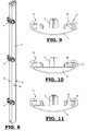
- the fastening elements (4) are symmetrical and comprise two holding elements (11), each intended for attaching a fence panel (3). These fastening elements (4) can be attached to a fence post (3) and can be prefitted thereto, as is illustrated in Fig. 8 . After attachment, a part (5) of these fastening elements (4) extends at least partially into the cavity (12) of the fence post (2), as is illustrated in Fig. 2 .
- This part (5) can in this case also be designed in such a manner that by attaching the fastening element (4) by means of a nail (6) through this part (5) to the fence post (2) after this part has been secured in the cavity (12), this part (5) is pushed in a direction at right angles to this nail (6) into the cavity (12) and thus securely clamps the fastening element (4) in the cavity.
- the holding elements (11) of these fastening elements (4) extend on either side of the fence post (2) and at least partly along the lateral sides (2b) of this fence post (2), as can also be seen in Fig. 2 . In this way, a very secure connection between the fastening elements (4) and the fence post (2) is achieved.
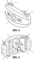
- Each holding element (11) comprises a first set of click-action means (8) for click-fitting a vertical wire (3b) of the fence panel (3) into a first cavity (7) of this holding element (11) in a direction at right angles to the plane of the fence panel (3) and a second set of click-action means (10) for click-fitting the fence panel (3) into a second cavity (9) of this holding element (11) in a direction parallel to the plane of this fence panel (3), as is illustrated in Figs. 2 to 7 and 9 to 11 .
- Figs. 9 to 11 the successive steps of click-fitting this vertical wire (3b) into the cavity (9) of the fence panel (3) are clearly illustrated.
- the vertical wire (3b) is moved in front of the opening of the holding element (11) which is defined by the first click-action means (8).
- This opening is narrower than the diameter of the vertical wire (3b).
- this vertical wire (3b) is pushed through said opening in a direction at right angles to the plane of the fence panel (3) and into the first cavity (7).
- the holding element (11) will temporarily be elastically deformed so as to temporarily enlarge said opening, so that the vertical wire (3b) is allowed through.
- the vertical wire (3b) is click-fitted into the first cavity (7) via the first click-action means (8).
- the vertical wire (3b) is situated in the cavity (7) and in front of the opening which is defined by the second click-action means (10). This opening is also narrower than the diameter of the vertical wire (3b). Subsequently, this vertical wire (3b) is pushed through the latter opening and into the second cavity (9). To this end, the holding element (11) will again be temporarily elastically deformed so as to temporarily enlarge the latter opening, so that the vertical wire (3b) is allowed through.
- the vertical wire (3b) is in this case click-fitted into the second cavity (9) via the second click-action means (10).
Landscapes
- Engineering & Computer Science (AREA)
- Architecture (AREA)
- Civil Engineering (AREA)
- Structural Engineering (AREA)
- Fencing (AREA)
Applications Claiming Priority (2)
| Application Number | Priority Date | Filing Date | Title |
|---|---|---|---|
| BE201000099 | 2010-02-19 | ||
| BE2010/0171A BE1019250A5 (nl) | 2010-02-19 | 2010-03-18 | Omheining. |
Publications (1)
| Publication Number | Publication Date |
|---|---|
| EP2362038A1 true EP2362038A1 (de) | 2011-08-31 |
Family
ID=44009811
Family Applications (1)
| Application Number | Title | Priority Date | Filing Date |
|---|---|---|---|
| EP11154665A Withdrawn EP2362038A1 (de) | 2010-02-19 | 2011-02-16 | Zaun |
Country Status (1)
| Country | Link |
|---|---|
| EP (1) | EP2362038A1 (de) |
Cited By (2)
| Publication number | Priority date | Publication date | Assignee | Title |
|---|---|---|---|---|
| ITBO20120234A1 (it) * | 2012-04-27 | 2013-10-28 | Casa Maurizio Della | Dispositivo per il fissaggio di pannelli di tamponamento in una barriera di delimitazione |
| US20220205273A1 (en) * | 2020-12-31 | 2022-06-30 | Frank Vingerhoets | Modular fencing system with gated access |
Citations (5)
| Publication number | Priority date | Publication date | Assignee | Title |
|---|---|---|---|---|
| FR2676488A1 (fr) | 1991-05-15 | 1992-11-20 | Dirickx Sa | Poteau de cloture perfectionne. |
| DE29811079U1 (de) * | 1998-06-20 | 1998-09-17 | SKS Drahtgitter GmbH + Co., 46395 Bocholt | Vorrichtung zur Befestigung eines Gitterzaunes an einem Zaunpfosten |
| EP1306502A1 (de) | 2001-10-29 | 2003-05-02 | Clotures Michel Willoquaux | Zaunpfosten |
| EP1736617A2 (de) | 2005-06-21 | 2006-12-27 | Bruno Godard | Zaunpfosten für Metallgitterpanele |
| FR2915224A1 (fr) * | 2007-04-20 | 2008-10-24 | Lippi La Cloture Sarl | Piece de fixation de panneaux de cloture et poteau de cloture comportant de telles pieces |
-
2011
- 2011-02-16 EP EP11154665A patent/EP2362038A1/de not_active Withdrawn
Patent Citations (5)
| Publication number | Priority date | Publication date | Assignee | Title |
|---|---|---|---|---|
| FR2676488A1 (fr) | 1991-05-15 | 1992-11-20 | Dirickx Sa | Poteau de cloture perfectionne. |
| DE29811079U1 (de) * | 1998-06-20 | 1998-09-17 | SKS Drahtgitter GmbH + Co., 46395 Bocholt | Vorrichtung zur Befestigung eines Gitterzaunes an einem Zaunpfosten |
| EP1306502A1 (de) | 2001-10-29 | 2003-05-02 | Clotures Michel Willoquaux | Zaunpfosten |
| EP1736617A2 (de) | 2005-06-21 | 2006-12-27 | Bruno Godard | Zaunpfosten für Metallgitterpanele |
| FR2915224A1 (fr) * | 2007-04-20 | 2008-10-24 | Lippi La Cloture Sarl | Piece de fixation de panneaux de cloture et poteau de cloture comportant de telles pieces |
Cited By (4)
| Publication number | Priority date | Publication date | Assignee | Title |
|---|---|---|---|---|
| ITBO20120234A1 (it) * | 2012-04-27 | 2013-10-28 | Casa Maurizio Della | Dispositivo per il fissaggio di pannelli di tamponamento in una barriera di delimitazione |
| EP2657435A1 (de) * | 2012-04-27 | 2013-10-30 | Maurizio Della Casa | Vorrichtung zur Befestigung von Abschlusspaneelen an einer Eindringschutzbarriere |
| US20220205273A1 (en) * | 2020-12-31 | 2022-06-30 | Frank Vingerhoets | Modular fencing system with gated access |
| US11846115B2 (en) * | 2020-12-31 | 2023-12-19 | Frank Vingerhoets | Modular fencing system with gated access |
Similar Documents
| Publication | Publication Date | Title |
|---|---|---|
| EP3227513B1 (de) | Zaunplattenverbinder | |
| CN102414383A (zh) | 栅栏 | |
| KR100954965B1 (ko) | 메쉬휀스 결속구 | |
| US10697516B2 (en) | Bracket device and method | |
| EP2598812A2 (de) | Verriegelungsmechanismus für platten | |
| CN107921922A (zh) | 将面板可解除地连接在结构上的紧固件、用于安全气囊的覆盖面板和具有结构和安全气囊的车辆 | |
| JP4159093B2 (ja) | 吊り足場用朝顔とその組立て施工法 | |
| US7185880B1 (en) | T-post puller claw | |
| EP2627840B1 (de) | Zaun | |
| CN101892763A (zh) | 紧固件 | |
| KR100779427B1 (ko) | 거푸집의 주밴드용 고정장치 | |
| KR101580095B1 (ko) | 철망펜스용 주주 | |
| BE1019250A5 (nl) | Omheining. | |
| EP3045616B1 (de) | Halter für Metallpfosten | |
| KR20110133743A (ko) | 울타리용 메시 연결고정구 | |
| JP3217294U (ja) | ロープ類係止装置 | |
| KR101810073B1 (ko) | 메시 고정 밴드 및 이를 이용한 메시 펜스 시공방법 | |
| KR200409296Y1 (ko) | 펜스 고정구 | |
| JP4143760B2 (ja) | フェンスバリケードの取付金具 | |
| JP7822902B2 (ja) | 網材の取付具及びそれを用いた柵体 | |
| JPH09228701A (ja) | 格子フェンス取付具及び格子フェンス | |
| JP7608036B1 (ja) | 取付具、取付部材、および撮像装置 | |
| JP2014155551A (ja) | 親綱支柱の取付構造 | |
| JP5580146B2 (ja) | 防護柵における抜止具及び該抜止具を備える防護柵 | |
| CN209290327U (zh) | 一种油管线束夹 |
Legal Events
| Date | Code | Title | Description |
|---|---|---|---|
| PUAI | Public reference made under article 153(3) epc to a published international application that has entered the european phase |
Free format text: ORIGINAL CODE: 0009012 |
|
| AK | Designated contracting states |
Kind code of ref document: A1 Designated state(s): AL AT BE BG CH CY CZ DE DK EE ES FI FR GB GR HR HU IE IS IT LI LT LU LV MC MK MT NL NO PL PT RO RS SE SI SK SM TR |
|
| AX | Request for extension of the european patent |
Extension state: BA ME |
|
| 17P | Request for examination filed |
Effective date: 20120206 |
|
| 17Q | First examination report despatched |
Effective date: 20130103 |
|
| GRAP | Despatch of communication of intention to grant a patent |
Free format text: ORIGINAL CODE: EPIDOSNIGR1 |
|
| INTG | Intention to grant announced |
Effective date: 20150807 |
|
| STAA | Information on the status of an ep patent application or granted ep patent |
Free format text: STATUS: THE APPLICATION IS DEEMED TO BE WITHDRAWN |
|
| 18D | Application deemed to be withdrawn |
Effective date: 20151218 |