EP2362039B1 - Griff mit drehhebel und drehblockierungsmechanismus - Google Patents
Griff mit drehhebel und drehblockierungsmechanismus Download PDFInfo
- Publication number
- EP2362039B1 EP2362039B1 EP11155009.1A EP11155009A EP2362039B1 EP 2362039 B1 EP2362039 B1 EP 2362039B1 EP 11155009 A EP11155009 A EP 11155009A EP 2362039 B1 EP2362039 B1 EP 2362039B1
- Authority
- EP
- European Patent Office
- Prior art keywords
- handle
- lever
- locking
- slug
- socket
- Prior art date
- Legal status (The legal status is an assumption and is not a legal conclusion. Google has not performed a legal analysis and makes no representation as to the accuracy of the status listed.)
- Not-in-force
Links
- 230000000903 blocking effect Effects 0.000 title claims description 30
- 230000007246 mechanism Effects 0.000 title claims description 24
- 210000002105 tongue Anatomy 0.000 description 36
- 230000013011 mating Effects 0.000 description 6
- 238000010276 construction Methods 0.000 description 4
- 238000003825 pressing Methods 0.000 description 4
- 230000001154 acute effect Effects 0.000 description 2
- 230000000994 depressogenic effect Effects 0.000 description 2
- 230000007935 neutral effect Effects 0.000 description 2
- 125000006850 spacer group Chemical group 0.000 description 2
- 230000006835 compression Effects 0.000 description 1
- 238000007906 compression Methods 0.000 description 1
- 230000000881 depressing effect Effects 0.000 description 1
- 230000000694 effects Effects 0.000 description 1
- 239000012634 fragment Substances 0.000 description 1
- 230000003100 immobilizing effect Effects 0.000 description 1
- 238000003780 insertion Methods 0.000 description 1
- 230000037431 insertion Effects 0.000 description 1
- 238000005304 joining Methods 0.000 description 1
- 238000003754 machining Methods 0.000 description 1
- 238000004519 manufacturing process Methods 0.000 description 1
- 239000000463 material Substances 0.000 description 1
- 230000000149 penetrating effect Effects 0.000 description 1
- 230000000717 retained effect Effects 0.000 description 1
- 230000000630 rising effect Effects 0.000 description 1
- 238000007493 shaping process Methods 0.000 description 1
- 210000003813 thumb Anatomy 0.000 description 1
Images


Classifications
-
- E—FIXED CONSTRUCTIONS
- E05—LOCKS; KEYS; WINDOW OR DOOR FITTINGS; SAFES
- E05B—LOCKS; ACCESSORIES THEREFOR; HANDCUFFS
- E05B13/00—Devices preventing the key or the handle or both from being used
- E05B13/10—Devices preventing the key or the handle or both from being used formed by a lock arranged in the handle
- E05B13/106—Devices preventing the key or the handle or both from being used formed by a lock arranged in the handle for handles pivoted about an axis perpendicular to the wing
Definitions
- Subject of the invention is a handle with a rotary lever, designed mainly for roof windows, provided with an incorporated mechanism blocking rotation in closed position, and a lock fixing that mechanism.
- EP 0460297 presents a solution consisting of a lever, a body, a locking disk with tongues, a locking cylinder with tongues, and an unlocking button.
- a solution consisting of a lever, a body, a locking disk with tongues, a locking cylinder with tongues, and an unlocking button.
- the locking cylinder and the locking disk set in the handle lever overlap and mesh, blocking by that the possibility of rotating the lever about the body.
- the cylinder and the disk overlap in a way enabling relative movement of lever in the body.
- the relative setting of the locking disk and the handle lever is achieved by connecting these elements by a screw, which joins the unlocking button with the locking disk.
- the drawback of that solution lies in considerable complexity of the locking mechanism located inside the lever and the handle body.
- GB2306309A disclose a grip which can be rotated from first, closed position, to a second open position, in which it can be tilt, and further to third position, in which grip can be turn.
- Blocking grip position is realised by a detent between grip and a base of the handle.
- the handle can switch its position by changing position of said detent.
- Said detent is located in the body of the handle and comprises an upstanding portion, which engages in shaped recess in the underside of the grip and prevents rotation of the grip.
- the body of the detent bears against a projectoon which is formed integrally with the lock barrel.
- the lock barrel is urged upwards by a compression spring.
- Application EP0521717A2 provides a handle blocking mechanism, in which blocking or unblocking of the handle is realised by plunger and the push button. Said plunger projects from fixing plate into a recess in the handle to prevent turning of the handle in its closed position and said push button can be depressed to push the plunger out of the recess to allow turning of the handle to its open position.
- the essence of the invention consists in that the subassembly of the locking mechanism, keeping the locking slug in its releasing or locking position, is completely placed inside the handle body.
- the subassembly of the mechanism keeping the locking slug in releasing position consists of a flat rotary disk with a tongue, set in the body, firmly connected with the stem being a part of the lever.
- the external form of the rotary disk with the tongue is defined by two sectors, the sum of their angles being equal to 360°, having a common center and different radii.
- the handle lever is being locked against turning in blocked position by simultaneous pressing the wall of the socket in the lever and the tongue on the locking slug.
- the pressure of the tongue and the lever socket on the locking slug is compensated by the reaction of the wall of the socket in the body.
- the locking slug is pressed by a spring out of the socket in the body.
- the spring in locking position, is pre-deflected causing a force keeping the locking slug in the handle socket.
- the push-button and the pusher serving to alter the position of the locking slug are placed in the handle lever.
- the handle can be provided with an internal lock with a two-position rotary insert, being actuated by a key, blocking the movement of the lever in one of its positions.
- the advantage of the suggested design is solving the problem of blocking the rotation of the lever by two-point pressure on the locking slug, applying elements connected with the rotary lever. That solution essentially increases the resistance of the handle against force breaking the lock by attempts to turn the lever.
- the two-position locking slug sliding within the handle body is being manually actuated and shifted to the releasing position by means of a push-button and a pusher located inside the handle lever.
- the back movement of the locking slug to the locking position is being forced by the force of a tensioned spring set in the handle body, the spring being an element constantly exerting a force on the locking slug towards its locked position.
- the locking slug using the force of the spring, slides-in partially into a mating socket in the handle lever, blocking by that any relative movement of the lever in the handle body.
- the slug is kept in that position by the force exerted by the spring.
- Unlocking and enabling rotary movement of the handle lever is done by pressing-in the push-button, which, using a pusher placed in that position directly above the locking slug, causes its shifting to the releasing position. Simultaneously, the locking slug is being moved out of the socket, making it possible to turn the lever.
- the locking slug is set with some clearance in the socket made in the handle body, enabling free axial play.
- the locking slug In the first phase of turning the lever in the handle about the body, the locking slug is kept in the pressed-in position due to blocking its face surface by the pusher turning together with the lever.
- the locking slug In the next phase of turning, the locking slug, despite freeing its face surface, stays in pressed-in position due to locking it by means of a tongue of the rotary disc mechanically coupled with the handle lever.
- the external contour of the flat rotary disk with the tongue can be defined by two circular sectors with a sum of angles equal to 360° having a common center and different radii, with the radius limiting the tongue being greater than the radius of the disk.
- the tongue In closed handle position, the tongue is outside the contour of the locking slug.
- the handle lever Upon pressing-in the locking slug, the handle lever can be turned together with the rotary disk due to setting on the same height the disk tongue and the groove, said groove concentric with the disc and made on the locking slug.
- polar coordinates When describing the mating of rotary elements it is convenient to apply polar coordinates.
- the angle of the circular sector limiting the size of the tongue is to be assumed so as to safeguard constant presence of the tongue in the groove. Only in the position, in which the rotation of the lever has to be blocked, it is indispensable that the tongue is outside the contour of the locking slug, enabling its sliding out of the socket in the body.
- the push-button can be released already during the first phase of rotation, in the moment when the tongue is at least partly in the groove.
- the mechanism blocking the rotation of the handle lever can be additionally fitted with a lock opened and closed by a key, which is a part of the push-button assembly modified for that purpose.
- the lock in its open state, is an element neutral with respect of all functions of the lever. Turning the lock to its closed position with the key, which is possible when the lever is blocked, stops the push-button, hampering by the same any rotation of the lever.
- the construction of the lever is specific by its simple structure, low manufacturing cost, and easy assembly, at the same time safeguarding it against attempts to unblocking from the outside.
- the lever provided with a blocking mechanism situated inside the body provides increased freedom in shaping the lever of the rotary part of the handle. This is especially important in the case of handles of roof windows in view of the close distance of the trajectory of the handle from other elements of the window.
- An essential advantage of the suggested solution is the absence of open and protruding elements of the locking mechanism, extending outside the contour of the lever and the handle body, both in open, as in closed position of the handle. This eliminates the risk of inadvertent damaging of the construction or caching of parts of clothes by salient elements.
- a definite advantage of such construction consists also in the esthetical value of the solution.
- Fig. 1 presents a cross-section of the handle through the axes of the handle and center of symmetry of the locking slug, showing the main elements in assembled condition, which rotate together with the lever.
- Fig. 3 is a section through the assembled handle, in a plane parallel to a plane led through the mounting holes in the body, the plane being tangent to the wall of the socket guiding the locking slug, and shows mainly the shape of the locking slug and its placement.
- Fig. 4 shows the location of the assembly of the push-button in the handle, in a section parallel to that presented in Fig. 3 , passing through the center of the locking slug.
- Fig. 5 is a view on the completely assembled handle, on the side of the rotary disc with the tongue mounted completely inside the handle body.
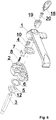
- Fig. 6 shows in exploded assembly view the complete handle with a key-operated lock, which blocks any movement of push-button.
- a complete handle in its first example of execution which is shown in exploded view in the drawing in Fig. 1 , consists of two basic parts - the handle 1 and the body 2.
- the handle, to which is fixed the pin 3, preferably having a square cross-section, is mounted in a way enabling rotation in the body 2 of the handle, using the stem 1a made on the handle 1 and the spacer washer 4, which plays also the role of an axial-and-radial slide bearing enabling rotation of the handle about the body.
- the joining is shown in Fig. 2 .
- the stem 1a is also used to fix on it the rotary disc 5.
- the part of the stem 1a protruding above the disk 5 is being expanded (burred) upon assembly, axially blocking the handle 1 in the body 2.
- the spacer ring 6 Between the disk 5 and the internal surface of the body 2 is placed the spacer ring 6 with an external diameter preferably equal to that of the disk 5.
- Making the ring of a material with a low coefficient of friction causes it to act at the same time as an axial slide bearing, easing operation of the lever.
- the locking mechanism includes, beside the disk 5, also the sliding locking slug 7 and the spring 8, which mate with the mechanism consisting of the push-button 9 and the pusher 10, built-in in the lever 1.
- the locking slug 7 with a square cross-section is sliding on the spring 8 in the socket 11, situated at a specific distance from the axis of rotation of the lever 1 in the direction perpendicular to the line determined by the centers of the fixing holes of the body 2.
- the rectangular form of the locking slug 7 safeguards it from unwanted rotation when turning the elements mating with it directly, i.e. the pusher 10 which, when the lever is being turned, executes a movement along an arc, sliding during a fragment of its trajectory on the face surface a of the locking slug 7, and the disk 5, the tongue of which slides on the surface b of the slug shown in Fig. 3 .
- the surface b which is the effect of machining a groove 13 in the locking slug 7, is made with a small bevel b', facilitating insertion of the tongue 12 when turning the disk 5.
- the locking slug 7 When the lever of the handle is in closed position, the locking slug 7 is positioned partly in the socket 14 in the body 2, and partly in the mating socket 14 in the lever 1 of the handle, blocking so the possibility to turn the lever about the handle body.
- the position of the socket 11 in the body 2 is therefore combined with the position of the socket 14 in the handle 1 and of the pusher 10 set when the lever is in closed position.
- the locking slug 7 is retained in the socket 14 by the constant force of the initial deflection of the spring 8, set in the dedicated pocket 15, hollowed in the locking slug 7.
- Unlocking and enabling turning movement of the lever 1 of the handle is done by pressing the push-button 9, shown in Fig.4 , which, by the intermediary of the pusher 10 located in that setting of the lever directly above the locking slug 7, forces the locking slug out of the socket 14 in the lever and pushes it completely into the socket 11 in the body of the handle, by the same making it possible to turn the lever.
- the locking slug 7 is placed with slight clearance typical for such elements in the socket 11 of the body, the side walls of which constitute guides for free longitudinal movement.
- the locking slug 7 is kept pressed into the socket 11 of the body due to blocking its face surface a by the pusher 10 moving together with the lever.
- the locking slug despite freeing its face surface a, stays in pressed-in position due to blocking it by the tongue 12.
- the tongue is outside the contour of the locking slug 7, which is the necessary condition to enable partial extension of the locking slug out of the socket 11 in the body and sliding it into the socket 14 in the lever.
- the pressed-in position of the locking slug 7 makes it possible to turn the lever in opening direction due to setting at an equal height the tongue 12 of the disk and the groove 13.
- the width and depth of the groove are slightly greater than the thickness of the tongue 12 of the disk, safeguarding loose mating of these two elements, while the action of the spring 8 causes a constant pressure of the surface b of the groove on the tongue.
- the angle of the sector limiting the size of the tongue 12, preferably an acute angle, is assumed so as to maintain at least partial presence of the tongue in the groove; therefore the push-button can be released already during the first phase of turning, at the moment when the tongue is at least partially in the groove.
- the maximum turning angle of the lever is 90°.
- the lever In order to block the lever again, the lever is to be turned in the opposite direction, to its extreme position. In that position, the tongue moves out from the groove 13, freeing the locking slug, which, forced by the spring, slides partly into the socket 14 in the lever, blocking the possibility to turn it. Sliding the locking slug 7 into the socked 14 forces the backward movement of the push-button 9 by the pusher 10, to its fully extended position, which makes it possible to repeat the operation of unlocking and turning the lever.
- Both the pusher 10 and the push-button 9, upon placing them in the guides make use of their elastic latches 21, which upon assembly play also the role of stroke limiters, and protect these elements from uncontrolled loosing.
- the mechanism locking the handle can be additionally fitted with a lock shown in Fig. 6 , which is opened and closed by key 18.
- the lock consists of a push-button 19, a modified version of the push button 9, and of a rotary insert 20.
- the additional lock In its open position, the additional lock is a neutral element in relation to all functions of the handle and keeps unchanged the functionality of the handle described in example 1. Turning the additional lock to closed position by the locking key 18, which is possible when the handle is in closed position, causes immobilizing of the assembly of the 20 and the push-button 19, hampering the locking slug from sliding out of the socket 14, and turning of the lever.
Landscapes
- Preventing Unauthorised Actuation Of Valves (AREA)
- Switch Cases, Indication, And Locking (AREA)
- Air Bags (AREA)
- Steering Devices For Bicycles And Motorcycles (AREA)
- Details Of Rigid Or Semi-Rigid Containers (AREA)
- Cookers (AREA)
Claims (8)
- Klinke mit drehbar im Körper (2) eingesetztem Griff, ausgestattet mit einem mittels des Druckknopfes (9) handbetätigten Mechanismus, der mithilfe eines im Körper (2) der Klinke befindlichen verschiebbaren Sperrzapfens das Drehen des Griffs in einer gewählten Position sperrt, wobei der verschiebbare Zapfen (7) in der Sperrichtung beweglich ist und in der Sperrposition mittels der durch die Spannung der Feder (8) erzeugten Kraft gehalten wird, dadurch gekennzeichnet, dass die den Sperrzapfen (7) in der Freigabe- bzw. Sperrposition haltende Unterbaugruppe aus einer flachen drehbaren Scheibe (5) mit dem Vorstand (12) besteht und sich als Ganzes im Körper (2) der starr mit dem einen Teil des Griffs (1) darstellenden Zapfen (1a) verbundenen Klinke befindet.
- Klinke nach Anspruch 1, dadurch gekennzeichnet, dass die äußere Form der drehbaren Scheibe (5) mit dem Vorstand (12) durch zwei Kreisausschnitte mit gemeinsamem Mittelpunkt und verschiedenen Radien definiert wird, deren Winkelsumme dem Vollwinkel gleich ist.
- Klinke nach Anspruch 1, dadurch gekennzeichnet, dass das Drehen des Griffes (1) der Klinke in der Sperrposition durch den gleichzeitigen Druck des Sitzes (14) im Griff (1) und des Vorstands (12) auf den Sperrzapfen (7) gesperrt wird.
- Klinke nach Anspruch 3, dadurch gekennzeichnet, dass der Druck des Vorstands (12) und des Sitzes (14) im Griff (1) auf den Sperrzapfen (7) durch die Reaktion des Sitzes (11) im Körper (2) ausbalanciert wird.
- Klinke nach Anspruch 1, dadurch gekennzeichnet, dass der Sperrzapfen (7) durch die Feder (8) in Richtung des Hinausschiebens aus dem Sitz (11) im Körper (2) gedrückt wird.
- Klinke nach Anspruch 5, dadurch gekennzeichnet, dass die Feder (8) in der Sperrposition eine Vordurchbiegung aufweist, deren Kraft den Sperrzapfen (7) im Sitz (14) in dem Griff (1) festhält.
- Klinke nach Anspruch 1, dadurch gekennzeichnet, dass der Druckknopf (9, 19) und der Stößel (10) zur Verstellung der Position des Sperrzapfens (7) im Griff (1) der Klinke angeordnet sind.
- Klinke nach Anspruch 7, dadurch gekennzeichnet, dass das Schloss mit dem mithilfe eines Schlüssels (18) verstellbaren und in einer der Positionen die Bewegung des Druckknopfes (19) sperrenden drehbaren Zweistellungseinsatz (20) im Griff (1) der Klinke untergebracht ist.
Applications Claiming Priority (1)
| Application Number | Priority Date | Filing Date | Title |
|---|---|---|---|
| PL390482A PL220641B1 (pl) | 2010-02-18 | 2010-02-18 | Klamka z obrotowym uchwytem i mechanizmem blokady obrotu |
Publications (3)
| Publication Number | Publication Date |
|---|---|
| EP2362039A2 EP2362039A2 (de) | 2011-08-31 |
| EP2362039A3 EP2362039A3 (de) | 2017-03-08 |
| EP2362039B1 true EP2362039B1 (de) | 2018-04-25 |
Family
ID=44168068
Family Applications (1)
| Application Number | Title | Priority Date | Filing Date |
|---|---|---|---|
| EP11155009.1A Not-in-force EP2362039B1 (de) | 2010-02-18 | 2011-02-18 | Griff mit drehhebel und drehblockierungsmechanismus |
Country Status (2)
| Country | Link |
|---|---|
| EP (1) | EP2362039B1 (de) |
| PL (1) | PL220641B1 (de) |
Families Citing this family (3)
| Publication number | Priority date | Publication date | Assignee | Title |
|---|---|---|---|---|
| CN103321502B (zh) * | 2013-07-10 | 2015-11-18 | 东风汽车公司 | 一种逃生窗锁止机构 |
| CA180465S (en) | 2017-09-28 | 2019-10-10 | Assa Abloy New Zealand Ltd | Window fastener |
| AU201811574S (en) | 2017-09-28 | 2018-04-13 | Assa Abloy New Zealand Ltd | Window fastener |
Family Cites Families (8)
| Publication number | Priority date | Publication date | Assignee | Title |
|---|---|---|---|---|
| FI77543C (fi) | 1985-12-19 | 1989-03-10 | Neste Oy | Ackumulator. |
| FR2650323A1 (fr) * | 1989-07-27 | 1991-02-01 | Ronis Sa | Poignee rotative a pouvoir de deverrouillage |
| DE9006484U1 (de) | 1990-06-08 | 1990-08-09 | Hoppe Gmbh & Co Kg, 3570 Stadtallendorf | Betätigungshandhabe |
| GB2258003B (en) * | 1991-07-01 | 1995-02-01 | Cego Ltd | Locking handle |
| DE9208674U1 (de) | 1992-06-27 | 1992-09-03 | Hoppe Gmbh & Co Kg, 3570 Stadtallendorf | Fenstergriff |
| JPH06264655A (ja) * | 1993-03-11 | 1994-09-20 | Takigen Seizo Kk | 引出し回転型扉用ロックハンドル装置 |
| GB2306309B (en) * | 1995-11-01 | 1998-12-23 | Plus Plan | Handle |
| GB2331549B (en) * | 1997-11-21 | 2001-08-01 | Securistyle Ltd | A handle assembly |
-
2010
- 2010-02-18 PL PL390482A patent/PL220641B1/pl unknown
-
2011
- 2011-02-18 EP EP11155009.1A patent/EP2362039B1/de not_active Not-in-force
Non-Patent Citations (1)
| Title |
|---|
| None * |
Also Published As
| Publication number | Publication date |
|---|---|
| EP2362039A3 (de) | 2017-03-08 |
| EP2362039A2 (de) | 2011-08-31 |
| PL390482A1 (pl) | 2011-08-29 |
| PL220641B1 (pl) | 2015-11-30 |
Similar Documents
| Publication | Publication Date | Title |
|---|---|---|
| US6872905B2 (en) | Pushbutton for latching and momentary contact functions | |
| US5384442A (en) | Control knob assembly for a cooking appliance | |
| US4324121A (en) | Key ring | |
| US7827837B2 (en) | Electro-mechanical lock assembly | |
| EP2362039B1 (de) | Griff mit drehhebel und drehblockierungsmechanismus | |
| FI79168B (fi) | Doerrlaos. | |
| US20040079123A1 (en) | Lock | |
| US4314124A (en) | Pushbutton contact | |
| EP2385199B1 (de) | Für Türen angepasstes Antipanik-Schloss | |
| CN217013636U (zh) | 锁定装置以及食物料理机 | |
| CN119900432B (zh) | 一种机械按键密码挂锁的开锁和换码结构 | |
| CN116146045A (zh) | 机械门锁及其操作机构 | |
| EP1984591B1 (de) | Kombinationsschloss für druckknopf | |
| EP1717389A1 (de) | Türgriff | |
| KR101695847B1 (ko) | 일시 열림 조작 기능을 겸한 트리거 레버를 이용한 래치볼트의 좌, 우수 전환기능을 갖는 디지털 도어락용 모티스 | |
| CN214062616U (zh) | 一种密码挂锁 | |
| EP3323965B1 (de) | Riegelschlossverriegelungsmechanismus | |
| CN212271838U (zh) | 解锁钥匙 | |
| US4295349A (en) | Door lock | |
| EP2385198B1 (de) | Für Türen angepasstes elektromechanisches Schloss | |
| JP5524732B2 (ja) | レバーハンドル錠 | |
| JP4425440B2 (ja) | スライダー機構 | |
| DE102023109472B3 (de) | Nottasteinrichtung einer Türverriegelung mit einem Notausschalter | |
| JP7702125B2 (ja) | プッシュボタン錠 | |
| DK2107188T4 (da) | Lås med et selektorelement |
Legal Events
| Date | Code | Title | Description |
|---|---|---|---|
| PUAI | Public reference made under article 153(3) epc to a published international application that has entered the european phase |
Free format text: ORIGINAL CODE: 0009012 |
|
| 17P | Request for examination filed |
Effective date: 20110317 |
|
| AK | Designated contracting states |
Kind code of ref document: A2 Designated state(s): AL AT BE BG CH CY CZ DE DK EE ES FI FR GB GR HR HU IE IS IT LI LT LU LV MC MK MT NL NO PL PT RO RS SE SI SK SM TR |
|
| AX | Request for extension of the european patent |
Extension state: BA ME |
|
| PUAL | Search report despatched |
Free format text: ORIGINAL CODE: 0009013 |
|
| AK | Designated contracting states |
Kind code of ref document: A3 Designated state(s): AL AT BE BG CH CY CZ DE DK EE ES FI FR GB GR HR HU IE IS IT LI LT LU LV MC MK MT NL NO PL PT RO RS SE SI SK SM TR |
|
| AX | Request for extension of the european patent |
Extension state: BA ME |
|
| RIC1 | Information provided on ipc code assigned before grant |
Ipc: E05B 3/06 20060101AFI20170130BHEP Ipc: E05B 13/10 20060101ALI20170130BHEP |
|
| STAA | Information on the status of an ep patent application or granted ep patent |
Free format text: STATUS: EXAMINATION IS IN PROGRESS |
|
| 17Q | First examination report despatched |
Effective date: 20170919 |
|
| GRAP | Despatch of communication of intention to grant a patent |
Free format text: ORIGINAL CODE: EPIDOSNIGR1 |
|
| STAA | Information on the status of an ep patent application or granted ep patent |
Free format text: STATUS: GRANT OF PATENT IS INTENDED |
|
| GRAS | Grant fee paid |
Free format text: ORIGINAL CODE: EPIDOSNIGR3 |
|
| INTG | Intention to grant announced |
Effective date: 20180223 |
|
| GRAA | (expected) grant |
Free format text: ORIGINAL CODE: 0009210 |
|
| STAA | Information on the status of an ep patent application or granted ep patent |
Free format text: STATUS: THE PATENT HAS BEEN GRANTED |
|
| AK | Designated contracting states |
Kind code of ref document: B1 Designated state(s): AL AT BE BG CH CY CZ DE DK EE ES FI FR GB GR HR HU IE IS IT LI LT LU LV MC MK MT NL NO PL PT RO RS SE SI SK SM TR |
|
| REG | Reference to a national code |
Ref country code: GB Ref legal event code: FG4D |
|
| REG | Reference to a national code |
Ref country code: CH Ref legal event code: EP |
|
| REG | Reference to a national code |
Ref country code: AT Ref legal event code: REF Ref document number: 993086 Country of ref document: AT Kind code of ref document: T Effective date: 20180515 |
|
| REG | Reference to a national code |
Ref country code: IE Ref legal event code: FG4D |
|
| REG | Reference to a national code |
Ref country code: DE Ref legal event code: R096 Ref document number: 602011047725 Country of ref document: DE |
|
| REG | Reference to a national code |
Ref country code: NL Ref legal event code: FP |
|
| REG | Reference to a national code |
Ref country code: LT Ref legal event code: MG4D |
|
| PG25 | Lapsed in a contracting state [announced via postgrant information from national office to epo] |
Ref country code: PL Free format text: LAPSE BECAUSE OF FAILURE TO SUBMIT A TRANSLATION OF THE DESCRIPTION OR TO PAY THE FEE WITHIN THE PRESCRIBED TIME-LIMIT Effective date: 20180425 Ref country code: SE Free format text: LAPSE BECAUSE OF FAILURE TO SUBMIT A TRANSLATION OF THE DESCRIPTION OR TO PAY THE FEE WITHIN THE PRESCRIBED TIME-LIMIT Effective date: 20180425 Ref country code: LT Free format text: LAPSE BECAUSE OF FAILURE TO SUBMIT A TRANSLATION OF THE DESCRIPTION OR TO PAY THE FEE WITHIN THE PRESCRIBED TIME-LIMIT Effective date: 20180425 Ref country code: FI Free format text: LAPSE BECAUSE OF FAILURE TO SUBMIT A TRANSLATION OF THE DESCRIPTION OR TO PAY THE FEE WITHIN THE PRESCRIBED TIME-LIMIT Effective date: 20180425 Ref country code: BG Free format text: LAPSE BECAUSE OF FAILURE TO SUBMIT A TRANSLATION OF THE DESCRIPTION OR TO PAY THE FEE WITHIN THE PRESCRIBED TIME-LIMIT Effective date: 20180725 Ref country code: ES Free format text: LAPSE BECAUSE OF FAILURE TO SUBMIT A TRANSLATION OF THE DESCRIPTION OR TO PAY THE FEE WITHIN THE PRESCRIBED TIME-LIMIT Effective date: 20180425 Ref country code: NO Free format text: LAPSE BECAUSE OF FAILURE TO SUBMIT A TRANSLATION OF THE DESCRIPTION OR TO PAY THE FEE WITHIN THE PRESCRIBED TIME-LIMIT Effective date: 20180725 |
|
| PG25 | Lapsed in a contracting state [announced via postgrant information from national office to epo] |
Ref country code: LV Free format text: LAPSE BECAUSE OF FAILURE TO SUBMIT A TRANSLATION OF THE DESCRIPTION OR TO PAY THE FEE WITHIN THE PRESCRIBED TIME-LIMIT Effective date: 20180425 Ref country code: HR Free format text: LAPSE BECAUSE OF FAILURE TO SUBMIT A TRANSLATION OF THE DESCRIPTION OR TO PAY THE FEE WITHIN THE PRESCRIBED TIME-LIMIT Effective date: 20180425 Ref country code: GR Free format text: LAPSE BECAUSE OF FAILURE TO SUBMIT A TRANSLATION OF THE DESCRIPTION OR TO PAY THE FEE WITHIN THE PRESCRIBED TIME-LIMIT Effective date: 20180726 Ref country code: RS Free format text: LAPSE BECAUSE OF FAILURE TO SUBMIT A TRANSLATION OF THE DESCRIPTION OR TO PAY THE FEE WITHIN THE PRESCRIBED TIME-LIMIT Effective date: 20180425 |
|
| REG | Reference to a national code |
Ref country code: AT Ref legal event code: MK05 Ref document number: 993086 Country of ref document: AT Kind code of ref document: T Effective date: 20180425 |
|
| PG25 | Lapsed in a contracting state [announced via postgrant information from national office to epo] |
Ref country code: PT Free format text: LAPSE BECAUSE OF FAILURE TO SUBMIT A TRANSLATION OF THE DESCRIPTION OR TO PAY THE FEE WITHIN THE PRESCRIBED TIME-LIMIT Effective date: 20180827 |
|
| REG | Reference to a national code |
Ref country code: DE Ref legal event code: R097 Ref document number: 602011047725 Country of ref document: DE |
|
| PG25 | Lapsed in a contracting state [announced via postgrant information from national office to epo] |
Ref country code: AT Free format text: LAPSE BECAUSE OF FAILURE TO SUBMIT A TRANSLATION OF THE DESCRIPTION OR TO PAY THE FEE WITHIN THE PRESCRIBED TIME-LIMIT Effective date: 20180425 Ref country code: CZ Free format text: LAPSE BECAUSE OF FAILURE TO SUBMIT A TRANSLATION OF THE DESCRIPTION OR TO PAY THE FEE WITHIN THE PRESCRIBED TIME-LIMIT Effective date: 20180425 Ref country code: SK Free format text: LAPSE BECAUSE OF FAILURE TO SUBMIT A TRANSLATION OF THE DESCRIPTION OR TO PAY THE FEE WITHIN THE PRESCRIBED TIME-LIMIT Effective date: 20180425 Ref country code: RO Free format text: LAPSE BECAUSE OF FAILURE TO SUBMIT A TRANSLATION OF THE DESCRIPTION OR TO PAY THE FEE WITHIN THE PRESCRIBED TIME-LIMIT Effective date: 20180425 Ref country code: EE Free format text: LAPSE BECAUSE OF FAILURE TO SUBMIT A TRANSLATION OF THE DESCRIPTION OR TO PAY THE FEE WITHIN THE PRESCRIBED TIME-LIMIT Effective date: 20180425 Ref country code: DK Free format text: LAPSE BECAUSE OF FAILURE TO SUBMIT A TRANSLATION OF THE DESCRIPTION OR TO PAY THE FEE WITHIN THE PRESCRIBED TIME-LIMIT Effective date: 20180425 |
|
| PG25 | Lapsed in a contracting state [announced via postgrant information from national office to epo] |
Ref country code: SM Free format text: LAPSE BECAUSE OF FAILURE TO SUBMIT A TRANSLATION OF THE DESCRIPTION OR TO PAY THE FEE WITHIN THE PRESCRIBED TIME-LIMIT Effective date: 20180425 Ref country code: IT Free format text: LAPSE BECAUSE OF FAILURE TO SUBMIT A TRANSLATION OF THE DESCRIPTION OR TO PAY THE FEE WITHIN THE PRESCRIBED TIME-LIMIT Effective date: 20180425 |
|
| PLBE | No opposition filed within time limit |
Free format text: ORIGINAL CODE: 0009261 |
|
| STAA | Information on the status of an ep patent application or granted ep patent |
Free format text: STATUS: NO OPPOSITION FILED WITHIN TIME LIMIT |
|
| 26N | No opposition filed |
Effective date: 20190128 |
|
| PG25 | Lapsed in a contracting state [announced via postgrant information from national office to epo] |
Ref country code: SI Free format text: LAPSE BECAUSE OF FAILURE TO SUBMIT A TRANSLATION OF THE DESCRIPTION OR TO PAY THE FEE WITHIN THE PRESCRIBED TIME-LIMIT Effective date: 20180425 |
|
| PGFP | Annual fee paid to national office [announced via postgrant information from national office to epo] |
Ref country code: BE Payment date: 20190115 Year of fee payment: 9 |
|
| REG | Reference to a national code |
Ref country code: CH Ref legal event code: PL |
|
| PG25 | Lapsed in a contracting state [announced via postgrant information from national office to epo] |
Ref country code: MC Free format text: LAPSE BECAUSE OF FAILURE TO SUBMIT A TRANSLATION OF THE DESCRIPTION OR TO PAY THE FEE WITHIN THE PRESCRIBED TIME-LIMIT Effective date: 20180425 Ref country code: LU Free format text: LAPSE BECAUSE OF NON-PAYMENT OF DUE FEES Effective date: 20190218 |
|
| REG | Reference to a national code |
Ref country code: IE Ref legal event code: MM4A |
|
| PG25 | Lapsed in a contracting state [announced via postgrant information from national office to epo] |
Ref country code: AL Free format text: LAPSE BECAUSE OF FAILURE TO SUBMIT A TRANSLATION OF THE DESCRIPTION OR TO PAY THE FEE WITHIN THE PRESCRIBED TIME-LIMIT Effective date: 20180425 |
|
| PG25 | Lapsed in a contracting state [announced via postgrant information from national office to epo] |
Ref country code: CH Free format text: LAPSE BECAUSE OF NON-PAYMENT OF DUE FEES Effective date: 20190228 Ref country code: LI Free format text: LAPSE BECAUSE OF NON-PAYMENT OF DUE FEES Effective date: 20190228 |
|
| PG25 | Lapsed in a contracting state [announced via postgrant information from national office to epo] |
Ref country code: IE Free format text: LAPSE BECAUSE OF NON-PAYMENT OF DUE FEES Effective date: 20190218 |
|
| PG25 | Lapsed in a contracting state [announced via postgrant information from national office to epo] |
Ref country code: TR Free format text: LAPSE BECAUSE OF FAILURE TO SUBMIT A TRANSLATION OF THE DESCRIPTION OR TO PAY THE FEE WITHIN THE PRESCRIBED TIME-LIMIT Effective date: 20180425 |
|
| PG25 | Lapsed in a contracting state [announced via postgrant information from national office to epo] |
Ref country code: MT Free format text: LAPSE BECAUSE OF NON-PAYMENT OF DUE FEES Effective date: 20190218 |
|
| REG | Reference to a national code |
Ref country code: BE Ref legal event code: MM Effective date: 20200229 |
|
| PG25 | Lapsed in a contracting state [announced via postgrant information from national office to epo] |
Ref country code: BE Free format text: LAPSE BECAUSE OF NON-PAYMENT OF DUE FEES Effective date: 20200229 |
|
| PG25 | Lapsed in a contracting state [announced via postgrant information from national office to epo] |
Ref country code: CY Free format text: LAPSE BECAUSE OF FAILURE TO SUBMIT A TRANSLATION OF THE DESCRIPTION OR TO PAY THE FEE WITHIN THE PRESCRIBED TIME-LIMIT Effective date: 20180425 |
|
| PG25 | Lapsed in a contracting state [announced via postgrant information from national office to epo] |
Ref country code: IS Free format text: LAPSE BECAUSE OF FAILURE TO SUBMIT A TRANSLATION OF THE DESCRIPTION OR TO PAY THE FEE WITHIN THE PRESCRIBED TIME-LIMIT Effective date: 20180825 |
|
| PG25 | Lapsed in a contracting state [announced via postgrant information from national office to epo] |
Ref country code: HU Free format text: LAPSE BECAUSE OF FAILURE TO SUBMIT A TRANSLATION OF THE DESCRIPTION OR TO PAY THE FEE WITHIN THE PRESCRIBED TIME-LIMIT; INVALID AB INITIO Effective date: 20110218 |
|
| PG25 | Lapsed in a contracting state [announced via postgrant information from national office to epo] |
Ref country code: MK Free format text: LAPSE BECAUSE OF FAILURE TO SUBMIT A TRANSLATION OF THE DESCRIPTION OR TO PAY THE FEE WITHIN THE PRESCRIBED TIME-LIMIT Effective date: 20180425 |
|
| PGFP | Annual fee paid to national office [announced via postgrant information from national office to epo] |
Ref country code: NL Payment date: 20230131 Year of fee payment: 13 |
|
| PGFP | Annual fee paid to national office [announced via postgrant information from national office to epo] |
Ref country code: FR Payment date: 20230124 Year of fee payment: 13 |
|
| PGFP | Annual fee paid to national office [announced via postgrant information from national office to epo] |
Ref country code: GB Payment date: 20230130 Year of fee payment: 13 Ref country code: DE Payment date: 20230131 Year of fee payment: 13 |
|
| P01 | Opt-out of the competence of the unified patent court (upc) registered |
Effective date: 20230419 |
|
| REG | Reference to a national code |
Ref country code: DE Ref legal event code: R119 Ref document number: 602011047725 Country of ref document: DE |
|
| REG | Reference to a national code |
Ref country code: NL Ref legal event code: MM Effective date: 20240301 |
|
| GBPC | Gb: european patent ceased through non-payment of renewal fee |
Effective date: 20240218 |
|
| PG25 | Lapsed in a contracting state [announced via postgrant information from national office to epo] |
Ref country code: NL Free format text: LAPSE BECAUSE OF NON-PAYMENT OF DUE FEES Effective date: 20240301 |
|
| PG25 | Lapsed in a contracting state [announced via postgrant information from national office to epo] |
Ref country code: NL Free format text: LAPSE BECAUSE OF NON-PAYMENT OF DUE FEES Effective date: 20240301 |
|
| PG25 | Lapsed in a contracting state [announced via postgrant information from national office to epo] |
Ref country code: DE Free format text: LAPSE BECAUSE OF NON-PAYMENT OF DUE FEES Effective date: 20240903 |
|
| PG25 | Lapsed in a contracting state [announced via postgrant information from national office to epo] |
Ref country code: GB Free format text: LAPSE BECAUSE OF NON-PAYMENT OF DUE FEES Effective date: 20240218 |
|
| PG25 | Lapsed in a contracting state [announced via postgrant information from national office to epo] |
Ref country code: FR Free format text: LAPSE BECAUSE OF NON-PAYMENT OF DUE FEES Effective date: 20240229 |
|
| PG25 | Lapsed in a contracting state [announced via postgrant information from national office to epo] |
Ref country code: GB Free format text: LAPSE BECAUSE OF NON-PAYMENT OF DUE FEES Effective date: 20240218 Ref country code: FR Free format text: LAPSE BECAUSE OF NON-PAYMENT OF DUE FEES Effective date: 20240229 Ref country code: DE Free format text: LAPSE BECAUSE OF NON-PAYMENT OF DUE FEES Effective date: 20240903 |