EP2362061B1 - Collier à coins pour colonne de montée de pétrole et de gaz avec antenne à basse fréquence et méthode correspondante - Google Patents
Collier à coins pour colonne de montée de pétrole et de gaz avec antenne à basse fréquence et méthode correspondante Download PDFInfo
- Publication number
- EP2362061B1 EP2362061B1 EP11154908.5A EP11154908A EP2362061B1 EP 2362061 B1 EP2362061 B1 EP 2362061B1 EP 11154908 A EP11154908 A EP 11154908A EP 2362061 B1 EP2362061 B1 EP 2362061B1
- Authority
- EP
- European Patent Office
- Prior art keywords
- riser
- spider
- riser pipe
- antenna
- pipe sections
- Prior art date
- Legal status (The legal status is an assumption and is not a legal conclusion. Google has not performed a legal analysis and makes no representation as to the accuracy of the status listed.)
- Not-in-force
Links
- 241000239290 Araneae Species 0.000 title claims description 88
- 238000000034 method Methods 0.000 title claims description 46
- 239000000853 adhesive Substances 0.000 claims description 3
- 230000001070 adhesive effect Effects 0.000 claims description 3
- 238000004891 communication Methods 0.000 description 17
- 238000012423 maintenance Methods 0.000 description 13
- 238000004519 manufacturing process Methods 0.000 description 5
- 238000005259 measurement Methods 0.000 description 5
- 238000005553 drilling Methods 0.000 description 4
- 238000012544 monitoring process Methods 0.000 description 4
- 238000013461 design Methods 0.000 description 3
- 238000010586 diagram Methods 0.000 description 3
- 239000004696 Poly ether ether ketone Substances 0.000 description 2
- 238000006243 chemical reaction Methods 0.000 description 2
- 230000008867 communication pathway Effects 0.000 description 2
- 230000007613 environmental effect Effects 0.000 description 2
- 238000007689 inspection Methods 0.000 description 2
- 229920002530 polyetherether ketone Polymers 0.000 description 2
- 238000012546 transfer Methods 0.000 description 2
- XLYOFNOQVPJJNP-UHFFFAOYSA-N water Substances O XLYOFNOQVPJJNP-UHFFFAOYSA-N 0.000 description 2
- 230000001133 acceleration Effects 0.000 description 1
- 238000013459 approach Methods 0.000 description 1
- 230000015556 catabolic process Effects 0.000 description 1
- 239000002131 composite material Substances 0.000 description 1
- 238000004590 computer program Methods 0.000 description 1
- 239000004020 conductor Substances 0.000 description 1
- 239000003822 epoxy resin Substances 0.000 description 1
- 238000009434 installation Methods 0.000 description 1
- 239000000463 material Substances 0.000 description 1
- 238000012986 modification Methods 0.000 description 1
- 230000004048 modification Effects 0.000 description 1
- 229920000647 polyepoxide Polymers 0.000 description 1
- 238000012545 processing Methods 0.000 description 1
- 239000007787 solid Substances 0.000 description 1
Images


Classifications
-
- E—FIXED CONSTRUCTIONS
- E21—EARTH OR ROCK DRILLING; MINING
- E21B—EARTH OR ROCK DRILLING; OBTAINING OIL, GAS, WATER, SOLUBLE OR MELTABLE MATERIALS OR A SLURRY OF MINERALS FROM WELLS
- E21B19/00—Handling rods, casings, tubes or the like outside the borehole, e.g. in the derrick; Apparatus for feeding the rods or cables
- E21B19/002—Handling rods, casings, tubes or the like outside the borehole, e.g. in the derrick; Apparatus for feeding the rods or cables specially adapted for underwater drilling
- E21B19/004—Handling rods, casings, tubes or the like outside the borehole, e.g. in the derrick; Apparatus for feeding the rods or cables specially adapted for underwater drilling supporting a riser from a drilling or production platform
-
- E—FIXED CONSTRUCTIONS
- E21—EARTH OR ROCK DRILLING; MINING
- E21B—EARTH OR ROCK DRILLING; OBTAINING OIL, GAS, WATER, SOLUBLE OR MELTABLE MATERIALS OR A SLURRY OF MINERALS FROM WELLS
- E21B17/00—Drilling rods or pipes; Flexible drill strings; Kellies; Drill collars; Sucker rods; Cables; Casings; Tubings
- E21B17/006—Accessories for drilling pipes, e.g. cleaners
-
- E—FIXED CONSTRUCTIONS
- E21—EARTH OR ROCK DRILLING; MINING
- E21B—EARTH OR ROCK DRILLING; OBTAINING OIL, GAS, WATER, SOLUBLE OR MELTABLE MATERIALS OR A SLURRY OF MINERALS FROM WELLS
- E21B19/00—Handling rods, casings, tubes or the like outside the borehole, e.g. in the derrick; Apparatus for feeding the rods or cables
- E21B19/10—Slips; Spiders ; Catching devices
-
- H—ELECTRICITY
- H01—ELECTRIC ELEMENTS
- H01Q—ANTENNAS, i.e. RADIO AERIALS
- H01Q1/00—Details of, or arrangements associated with, antennas
- H01Q1/12—Supports; Mounting means
Definitions
- the present invention relates to the oil and gas industry. More particularly, the present invention relates to an oil and gas spider apparatus with a built-in antenna and related methods for use in a riser management system that monitors and manages a plurality of marine riser assets.
- a riser is a string of pipe between the sea bottom and ship or rig.
- Oil and gas riser pipe strings are assembled using a device known as a "spider.”
- the spider feeds and connects each section of riser pipe in the string.
- Spiders can have different configurations. Some spiders are made of a solid ring that the riser feeds through; some spiders are made of two pieces that close around a riser pipe and then feed the riser pipe through. For each configuration type of spider, the riser pipes are all fed into the spider in the same orientation.
- riser components are individually lifted from the deck of a vessel, connected to each other at the riser spider, and run down.
- Riser joints which comprise the major length of the riser string, are fabricated in lengths ranging from 15.2 m to 27.4 m (50' to 90').
- the portion of the riser string that is fully made up is landed on the riser spider.
- the next riser joint is then picked up and placed just over the spider, immediately above the suspended riser string.
- the two riser sections are then joined by means of a mechanical connector.
- riser Lifecycle Management Systems have been described, such as in co-owned United States Patent Publication Number US 2008/0128138 A1 .
- Such riser lifecycle management systems can provide asset managers a list of all the riser assets allocated to specific vessels and provide a further breakdown of those assets that are currently deployed, are on deck, or are out for maintenance, along with the expected return date; a list of upcoming scheduled maintenance events; an estimate of the amount of operational life being expanded by a particular riser asset; and an estimate of the total amount of operational life used by a particular riser asset, along with the details of the most damaging events (i.e., a certain hurricane event).
- Such riser lifecycle management systems can include, for example, a central database that can be used by field and maintenance personnel to maintain and communicate critical riser information, and that can enhance both routine maintenance scheduling and identifying a need for an unscheduled maintenance event.
- Drill pipes have a smaller diameter than riser pipes.
- US 2009/0188675 A1 relates to apparatus identification systems and methods relating to drilling rigs and discloses features generally corresponding to the preamble of claim 1 herein.
- Embodiments can, for example, enhance a riser management system that monitors and manages a plurality of riser assets, e.g., marine riser assets.
- Embodiments of the present invention include, for example, an apparatus in accordance with claim 1.
- the apparatus can include a riser spider to connect a plurality of riser pipe sections during assembly of a riser pipe string.
- the riser spider can be positioned to form an annulus around a first section of the plurality of riser pipe sections and to support the first section of the plurality of riser pipe sections during connection to a second section of the plurality of riser pipe sections.
- the apparatus can include an antenna to read a plurality of radio frequency identification tags attached to outsides of the plurality of riser pipe sections, the antenna including an oblong loop attached to and substantially spanning about half of an internal surface of the riser spider so that the antenna follows the contour of the riser spider.
- Embodiments of the present invention can include, for example, a method of tracking marine riser pipe sections in accordance with claim 8.
- the method can include, for example, providing a plurality of radio frequency identification tags attached to outsides of and associated with a plurality of riser pipe sections.
- the method can include, for example, utilizing a riser spider to connect the plurality of riser pipe sections during assembly of a riser pipe string.
- the riser spider can form an annulus around a first section of the plurality of riser pipe sections and support the first section of the plurality of riser pipe sections during connection to a second section of the plurality of riser pipe sections.
- the method can include, for example, reading each of the plurality of radio frequency identification tags during a feeding of the associated riser pipe section through the riser spider utilizing an antenna.
- the antenna can include an oblong loop attached to and substantially spanning about half of an internal surface of the riser spider so that the antenna follows the contour of the riser spider.
- Embodiments of the present invention can further include, for example, a method of tracking a plurality of riser pipe sections.
- the method can include, for example, for each of a plurality of riser pipe sections, receiving riser pipe section identification data from a radio frequency identification tag attached to an outside of and associated with a riser pipe section utilizing an antenna during a feeding of the riser pipe section through a riser spider during assembly of a riser pipe string to separately identify each one of the plurality of riser pipe sections from each other of the plurality of riser pipe sections.
- the antenna can include an oblong loop attached to and substantially spanning about half of an internal surface of the riser spider so that the antenna follows the contour of the riser spider.
- the method can include, for example, determining a relative deployed position location of the each of the plurality of riser pipe sections to form the riser pipe string.
- embodiments of the present invention advantageously provide a solution for various riser spider configurations, including spiders that are made of two pieces that close around a riser pipe.
- riser assets e.g., marine riser assets.
- Embodiments of the present invention include, for example, RFID tags, e.g., 125 kHz RFID tags.
- 125kHz RFID tags 71 can be directional and can only be read on one side, defining a read field 203.
- a reader antenna 202 must be facing the 125kHz RFID tags 71 so that its read field 204 is directed toward the antenna 202.
- embodiments include directional RFID tag 71, as illustrated in FIG. 3 , being positioned on a riser pipe 29 so that the tag's read field 203 is directed outward.
- a spider 32 which feeds and connects each section of riser pipe in the string, surrounds or envelopes each riser pipe as it is added to the string so that an internal surface 205 of the spider 32 faces the a directional RFID tag 71 positioned on a riser pipe 29 and directed outward.
- some spiders 32 are made of two pieces 32A, 32B that close around a riser pipe 29 and then feeds the riser pipe through.
- embodiments of the present invention can include, for example, placement of an antenna 201 on an internal surface 205 of a spider 32, or a portion of spider 32A.
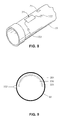
- An antenna 201 embodiment can include, for example, an oblong loop that follows the contour of the spider 32, or a portion of spider 32A, for example, an oblong loop attached to and substantially spanning about half of an internal surface 205 of a riser spider 32, or about 180 degrees of the ring defined by the spider.
- one piece 32A of a two-piece spider 32 can include an antenna 201 embodiment having an oblong loop that follows the contour of the riser spider to thereby provide maximum readability.
- Embodiments of the present invention include, for example, an apparatus.
- the apparatus can include, for example, a riser spider 32 to connect a plurality of riser pipe sections 29 during assembly of a riser pipe string.
- the riser spider 32 can form an annulus around a first section of the plurality of riser pipe sections and support the first section of the plurality of riser pipe sections during connection to a second section of the plurality of riser pipe sections.
- the apparatus can include, for example, an antenna 201 to read a plurality of radio frequency identification tags 71 attached to outsides of the plurality of riser pipe sections 29.
- the antenna can include an oblong loop attached to and substantially spanning about half of an internal surface of the riser spider so that the antenna follows the contour of the riser spider.
- the apparatus can also include an adhesive 231 (see, e.g., FIG. 9 ) to attach the antenna to the internal surface of the spider and a protectant 230 (see, e.g., FIG. 9 ) to protect the antenna from an ocean environment.
- the protectant 230 can seal the antenna to the spider.
- An exemplary embodiment can include use of commercially available polyetheretherketone (PEEK) or marginalized epoxy resin for subsea applications.
- attachment of the antenna to the spider can be through clamps, wiring, and other approaches as understood by those skilled in the art.
- the apparatus can also include a low-frequency, substantially stationary, passive reader 73 of radio frequency identification tags. (See, e.g., FIG. 7B .) The reader 73 can be operably connected to the antenna.
- the riser spider can include two portions 32A, 32B that together close around the first section of the plurality of riser pipe sections 29 to form the annulus, with each portion comprising a semi-circumference of the annulus.
- the riser spider 32 can also include the two portions being connected by a hinge 232 (see, e.g., FIG. 9 ).
- Placement of the antenna 201 on the internal surface 205 of the spider 32 allows the tag 71 on the riser pipe 29 to be read as it moves through the spider, automatically and without manually bringing a reader to the riser pipe 29 or the riser pipe 29 to a reader.
- embodiments of the present invention do not interfere with normal operation of the riser pipe string.
- embodiments of the present invention advantageously provide a solution for various riser spider configurations, including spiders that are made of two pieces that close around a riser pipe.
- embodiments of the present invention include, for example, a method 210 of tracking marine riser pipe sections 29.
- the method 210 can include, for example, providing a plurality of radio frequency identification tags 71 attached to outsides of and associated with a plurality of riser pipe sections 211.
- the method 210 can include, for example, utilizing a riser spider 32 to connect the plurality of riser pipe sections 29 during assembly of a riser pipe string 212.
- the riser spider can form an annulus around a first section of the plurality of riser pipe sections and support the first section of the plurality of riser pipe sections during connection to a second section of the plurality of riser pipe sections.
- the method 210 can include, for example, reading each of the plurality of radio frequency identification tags 71 during a feeding of the associated riser pipe section through the riser spider 32 utilizing an antenna 213.
- the antenna 201 can include an oblong loop attached to and substantially spanning about half of an internal surface of the riser spider 32 so that the antenna 201 follows the contour of the riser spider 32.
- embodiments of the present invention include, for example, a method 220 of tracking a plurality of riser pipe sections 29.
- the method 220 can include, for example, for each of a plurality of riser pipe sections 29, receiving riser pipe section identification data from a radio frequency identification tag 71 attached to an outside of and associated with a riser pipe section utilizing an antenna 201 during a feeding of the riser pipe section through a riser spider during assembly of a riser pipe string to separately identify each one of the plurality of riser pipe sections from each other of the plurality of riser pipe sections 221.
- the antenna 201 can include an oblong loop attached to and substantially spanning about half of an internal surface 205 of the riser spider so that the antenna 201 follows the contour of the riser spider.
- the method 220 can include, for example, determining a relative deployed position location of the each of the plurality of riser pipe sections 29 to form the riser pipe string 222.
- FIGS. 1-9 illustrate an embodiment of a Riser Lifecycle Monitoring System (RLMS) which provides an integrated tool designed to improve the lifecycle performance of a marine riser through the application of remote diagnostics, online asset management, and readily accessible riser asset maintenance history, and to permit remote management of riser assets, with particular emphasis on riser joints.
- the riser lifecycle management system includes integrated hardware and software/program product components which can be combined in a central database preferably located on shore. This database can store asset information on every riser lifecycle management system equipped riser in the world. It also can permit transfer of a riser asset from one vessel to another while retaining all historic data.
- the vessel computers in turn, can retrieve the data from sensors placed, for example, on each riser asset.
- the riser lifecycle management system beneficially provides for acquisition of riser load history data.
- acquisition can include gathering sensor data, multiplexing that data, and communicating it through the water column up to a vessel, while allowing for an acceptable level of fault tolerance.
- the data acquired depends on the type of sensor used on the riser asset.
- Such data provided by embodiments of the system can also allow for scheduled and unscheduled maintenance and for control of an associated riser tensioning system.
- the riser lifecycle management system 30 includes portions onshore and portions at each of the vessel locations.
- the portion of the riser lifecycle management system 30 located at an onshore or other centralized location or locations can include at least one computer to remotely manage riser assets for a plurality of separate vessel locations defining a riser lifecycle management server 51 positioned in communication with an onshore local area communication network 53.
- the riser lifecycle management server 51 can include a processor 55 and memory 57 coupled to the processor 55.
- the memory 57 can include, for example, program product 120.
- the riser lifecycle management system 30 can also include a data warehouse 63 which can store relevant data on every piece of riser lifecycle management system equipped riser components anywhere in the world.
- the data warehouse 63 is assessable to the processor 55 of the riser lifecycle management server 51 and can be implemented in hardware, software, or a combination thereof.
- the data warehouse 63 can include at least one centralized database 65 configured to store asset information for a plurality of riser pipe sections 29, i.e., riser joints, and other riser assets of interest deployed at a plurality of separate vessel locations.
- the asset information can include, for example, the part number, serial number, relevant manufacturing records, operational procedures, and all maintenance records (including detailed information on the nature of the maintenance), just to name a few.
- the database 65 can also retain deployment and load history information, which can be acquired automatically from shipboard computers 41 located on each riser lifecycle management system equipped vessel 27. See also, e.g., FIG. 7A .
- the riser lifecycle management system 30 can also include riser pipe section measurement instrument modules 91 and a subsurface communication medium 95, described herein.
- the riser lifecycle management system 30 can also include, in communication with the onshore communication network 53, a receiver/transmitter 54 providing, for example, satellite-based communication to a plurality of vessels/drilling/production facilities each having a receiver/transmitter 44.
- the riser lifecycle management system 30 can also include, for example, a global communication network 61 providing a communication pathway between the shipboard computers 41 of each respective vessel 27 and the riser lifecycle management server 51 to permit transfer of riser asset information between the shipboard computers 41 and the riser life cycle management server 51.
- the portion of the riser lifecycle management system 30 located at each at each of the vessel 27 locations can include, for example, a shipboard computer 41 in communication with a local shipboard communication network 43, e.g., LAN, or local area network.
- the shipboard computer 41 can include a processor 45, and memory 47 coupled to the processor 45.
- the memory 47 can include, for example, program product 120'.
- At least one database 49 accessible to the processor 45 of a shipboard computer 41 is also provided which can be used to store asset information for each of the plurality of riser joints deployed from the vessel 27.
- asset information can include riser joint identification data, riser joint deployment and location data, and riser joint load history data.
- a receiver/transmitter 44 providing, for example, satellite-based communication to onshore facilities.
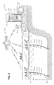
- the riser lifecycle management system 30 can include offshore drilling and/or production system 21, including a deployed riser pipe or conductor defining a riser string 23 extending between subsea wellhead system 25 and a floating vessel 27, such as, for example, a dynamically positionable vessel.
- the riser string 23 includes multiple riser sections or joints 29 connected together, for example, by a bolted flange or other means known to those skilled in the art.
- the vessel 27 includes a well bay 31 extending through a floor of the vessel 27, and typically includes a riser spider 32 positioned on an operational platform 33 in a well bay 31 to support the riser string 23 when riser joint connections are being made or broken during running or retrieval of the riser string 23.
- Embodiments of the present invention apply to both drilling and production risers.
- the vessel 27 also includes a tensioning system 35, located on the operational platform 33, which provides both lateral load resistance and vertical tension, preferably applied to a slip or tensioning ring 37 attached to the top of the riser string 23.
- the riser identification and deployment data for each riser joint 29 is communicated, for example, to the shipboard computer 41 by means of a tag such as, for example, an RFID chip or tag 71 (see, e.g., FIG. 8 ) positioned on each riser joint 29, and an appropriate reader 73, for example, mounted on deck or otherwise connected to the vessel 27 at or adjacent the surface of the sea and operably coupled to or otherwise in communication with the shipboard computer 41 through the local shipboard communication network 43.
- a tag such as, for example, an RFID chip or tag 71 (see, e.g., FIG. 8 ) positioned on each riser joint 29, and an appropriate reader 73, for example, mounted on deck or otherwise connected to the vessel 27 at or adjacent the surface of the sea and operably coupled to or otherwise in communication with the shipboard computer 41 through the local shipboard communication network 43.
- the system 30 can also include riser joint measurement instrument modules 91 each positioned to sense a load represented by strain, riser pipe curve, or accelerometer data, etc. imposed on a separate one of the riser joints 29 forming the riser string 23, a riser joint load data receiver 93 mounted or otherwise connected to the vessel 27 at or adjacent the surface of the sea and operably coupled to the local shipboard communication network 43 to receive load data for each of the deployed riser joints 29 from the riser joint measurement instrument modules 91, and a subsurface communication medium 95 illustrated as provided via a series of replaceable wireless data telemetry stations providing a communication pathway between each of the joint measurement instrument modules 91 and the riser joint load data receiver 93 through a water column associated with the riser string 23.
- riser joint measurement instrument modules 91 each positioned to sense a load represented by strain, riser pipe curve, or accelerometer data, etc. imposed on a separate one of the riser joints 29 forming the riser string 23, a riser joint load data receiver 93 mounted or otherwise connected to the vessel 27
- the measurement instrument modules 91 can determine the magnitude of the loads imposed on the riser string 23 to calculate the magnitude of the stress at various locations on the riser joint 29 or other riser asset. Examples can include excessive stresses, deflections, accelerations, and high frequency alternating stresses in a cross flow motion due to, for example, vortex induced vibration caused by vortices VX. There are a number of methods under which the riser stresses can be measured. In one embodiment, the riser pipe strain is read at a sensor 103, since conversion of strain data to stresses is fairly straightforward and can be done via a relatively simple computer program element.
- the riser dynamics can be obtained via accelerometers, which may require a more complex set of operations for conversion to material stress from which the operational (e.g., fatigue) life can then be calculated.
- the load data sent to the riser lifecycle management server 51 can be in either raw data or converted to local stresses by the shipboard computer 41, or some intermediate form if some processing is accomplished by the instrument modules 91.
- the sensor 103 is carried by a thin clamp-on composite mat (not shown), which can be used to accurately determine the deflection in the riser joint 29.
- Embodiments of the riser lifecycle management system 30 can also include various methods relating to monitoring and managing a plurality of marine riser assets.
- the shipboard computer 41 can compare ID data with the list of recently recorded tags. If a duplicate asset is reported, it is disregarded. That is, when utilizing automated reading sensors, the same riser asset may be scanned multiple times while being landed on the spider 32 or during the normal course of handling.
- the preferred handling procedures can include disregarding duplicate records or duplicate reads within a preselected time period.
- Embodiments of the apparatuses and associated methods according to the present invention provide several advantages and enhancements, in the context of a riser lifecycle management system 30.
- embodiments provide for automatically reading identification tags on riser pipes, without requiring hand-held readers, manual processes, or interference with normal operations. That is, embodiments provide a low frequency (LF), stationary reader antenna built into a riser spider that allows riser pipes to be read automatically, as the pipes are fed through the riser spider.
- LF low frequency
- embodiments of the present invention can track marine riser pipe sections to thereby enable the system to notify automatically an operator of both routine and unscheduled maintenance events.
- a routine maintenance event is one that is scheduled sometime in advance, but may have been aided by load history information in the database.
- An unscheduled maintenance event is one associated with an unexpected incident. For example, one or more riser joints in a string that has been subjected to a direct hit by a hurricane may reach a preset fatigue life trigger level, requiring an inspection of the riser joint at the very least. In such a scenario, the operator would have a high degree of confidence that the remaining riser assets are suitable for marine deployment, reducing the down time associated with inspection of the entire riser string.
Landscapes
- Engineering & Computer Science (AREA)
- Life Sciences & Earth Sciences (AREA)
- Geology (AREA)
- Mining & Mineral Resources (AREA)
- Mechanical Engineering (AREA)
- Physics & Mathematics (AREA)
- Environmental & Geological Engineering (AREA)
- Fluid Mechanics (AREA)
- General Life Sciences & Earth Sciences (AREA)
- Geochemistry & Mineralogy (AREA)
- Earth Drilling (AREA)
Claims (15)
- Appareil comprenant :un collier à coins de colonne montante (32) pour raccorder une pluralité de sections de tuyaux de colonne montante (29) au cours de l'assemblage d'un train de tuyaux de colonne montante (23), le collier à coins de colonne montante étant destiné à former un anneau autour d'une première section de la pluralité de sections de tuyaux de colonne montante (29) et supporter la première section de la pluralité de sections de tuyaux de colonne montante au cours du raccordement à une seconde section de la pluralité de sections de tuyaux de colonne montante ;l'appareil comprenant en outre :une antenne (201) pour lire une pluralité d'étiquettes d'identification de fréquence radioélectrique (71) fixées aux extérieurs de la pluralité de sections de tuyaux de colonne montante (29), caractérisé en ce que l'antenne comprend une boucle oblongue fixée à une surface interne (205) du collier à coins de colonne montante (32) et couvrant sensiblement environ la moitié de celle-ci de sorte que l'antenne suive le contour du collier à coins de colonne montante.
- Appareil selon la revendication 1, dans lequel le collier à coins de colonne montante (32) comprend :deux parties (32A, 32B) qui se referment conjointement autour de la première section de la pluralité de sections de tuyaux de colonne montante (29) pour former l'anneau, chaque partie comprenant une demi-circonférence de l'anneau.
- Appareil selon la revendication 2, dans lequel les deux parties (32A, 32B) sont raccordées par une charnière (232).
- Appareil selon l'une quelconque des revendications précédentes, comprenant en outre :un adhésif (231) pour fixer l'antenne (201) à la surface interne (205) du collier à coins (32) ; etun dispositif de protection (230) pour protéger l'antenne (201) d'un environnement océanique.
- Appareil selon l'une quelconque des revendications précédentes, comprenant en outre :un lecteur passif sensiblement stationnaire de faible fréquence (73) d'étiquettes d'identification de fréquence radioélectrique (71), le lecteur étant connecté en service à l'antenne (201).
- Appareil selon l'une quelconque des revendications précédentes, dans lequel les étiquettes d'identification de fréquence radioélectrique (71) sont directionnelles.
- Appareil selon l'une quelconque des revendications précédentes, dans lequel les étiquettes d'identification de fréquence radioélectrique (71) sont des étiquettes de faible fréquence de 125 kHz.
- Procédé (210) permettant de suivre des sections marines de tuyaux de colonne montante (29), le procédé comprenant :la fourniture (211) d'une pluralité d'étiquettes d'identification de fréquence radioélectrique (71) fixées aux extérieurs d'une pluralité de sections de tuyaux de colonne montante et associées à celles-ci ;l'utilisation (212) d'un collier à coins de colonne montante (32) pour raccorder la pluralité de sections de tuyaux de colonne montante au cours de l'assemblage d'un train de tuyaux de colonne montante (23), le collier à coins de colonne montante étant destiné à former un anneau autour d'une première section de la pluralité de sections de tuyaux de colonne montante et à supporter la première section de la pluralité de sections de tuyaux de colonne montante au cours du raccordement à une seconde section de la pluralité de sections de tuyaux de colonne montante ; etla lecture (213) de chacune de la pluralité d'étiquettes d'identification de fréquence radioélectrique (71) au cours de l'acheminement de la section de tuyau de colonne montante associée à travers le collier à coins de colonne montante (32) en utilisant une antenne (201), l'antenne comprenant une boucle oblongue fixée à une surface interne (205) du collier à coins de colonne montante (32) etcouvrant sensiblement environ la moitié de celle-ci de sorte que l'antenne suive le contour du collier à coins de colonne montante.
- Procédé (210) selon la revendication 8, dans lequel le collier à coins de colonne montante (32) comprend :deux parties (32A, 32B) qui se referment conjointement autour de la première section de la pluralité de sections de tuyaux de colonne montante (29) pour former l'anneau, chaque partie comprenant une demi-circonférence de l'anneau.
- Procédé (210) selon la revendication 9, dans lequel les deux parties (32A, 32B) sont raccordées par une charnière (232).
- Procédé (210) selon l'une quelconque des revendications 8 à 10, dans lequel un adhésif (231) fixe l'antenne (201) à la surface interne (205) du collier à coins de colonne montante (32) ; et dans lequel un dispositif de protection (230) protège l'antenne d'un environnement océanique.
- Procédé (210) selon l'une quelconque des revendications 8 à 11, dans lequel l'étape de lecture de chacune de la pluralité d'étiquettes d'identification de fréquence radioélectrique (71) comprend en outre un lecteur passif sensiblement stationnaire de faible fréquence (73) d'étiquettes d'identification de fréquence radioélectrique, le lecteur étant connecté en service à l'antenne (201).
- Procédé (210) selon l'une quelconque des revendications 8 à 12, dans lequel les étiquettes d'identification de fréquence radioélectrique (71) sont directionnelles.
- Procédé (210) selon l'une quelconque des revendications 8 à 13, dans lequel les étiquettes d'identification de fréquence radioélectrique (71) sont des étiquettes de faible fréquence de 125 kHz.
- Procédé selon la revendication 8, le procédé comprenant en outre :la détermination d'un emplacement de position déployée relative de chacune de la pluralité de sections de tuyaux de colonne montante (29) pour former le train de tuyaux de colonne montante (23).
Applications Claiming Priority (1)
| Application Number | Priority Date | Filing Date | Title |
|---|---|---|---|
| US12/710,707 US8464946B2 (en) | 2010-02-23 | 2010-02-23 | Oil and gas riser spider with low frequency antenna apparatus and method |
Publications (3)
| Publication Number | Publication Date |
|---|---|
| EP2362061A2 EP2362061A2 (fr) | 2011-08-31 |
| EP2362061A3 EP2362061A3 (fr) | 2015-07-29 |
| EP2362061B1 true EP2362061B1 (fr) | 2016-11-02 |
Family
ID=43827320
Family Applications (1)
| Application Number | Title | Priority Date | Filing Date |
|---|---|---|---|
| EP11154908.5A Not-in-force EP2362061B1 (fr) | 2010-02-23 | 2011-02-17 | Collier à coins pour colonne de montée de pétrole et de gaz avec antenne à basse fréquence et méthode correspondante |
Country Status (6)
| Country | Link |
|---|---|
| US (1) | US8464946B2 (fr) |
| EP (1) | EP2362061B1 (fr) |
| AU (1) | AU2011200754B2 (fr) |
| BR (1) | BRPI1100280B1 (fr) |
| MY (1) | MY153848A (fr) |
| SG (1) | SG173969A1 (fr) |
Families Citing this family (27)
| Publication number | Priority date | Publication date | Assignee | Title |
|---|---|---|---|---|
| GB0425008D0 (en) | 2004-11-12 | 2004-12-15 | Petrowell Ltd | Method and apparatus |
| US10262168B2 (en) | 2007-05-09 | 2019-04-16 | Weatherford Technology Holdings, Llc | Antenna for use in a downhole tubular |
| GB0720421D0 (en) * | 2007-10-19 | 2007-11-28 | Petrowell Ltd | Method and apparatus for completing a well |
| US9051785B2 (en) * | 2008-02-11 | 2015-06-09 | Vetco Gray Inc. | Oil and gas riser spider with low frequency antenna apparatus and method |
| GB0804306D0 (en) | 2008-03-07 | 2008-04-16 | Petrowell Ltd | Device |
| BR112012002356A2 (pt) * | 2009-08-02 | 2019-09-24 | Cameron Int Corp | antena rfid em arco |
| GB0914650D0 (en) | 2009-08-21 | 2009-09-30 | Petrowell Ltd | Apparatus and method |
| CN102971485B (zh) | 2010-04-30 | 2016-01-13 | S.P.M.流量控制股份有限公司 | 测试和认证石油和天然气设备的机器、系统、计算机实施的方法 |
| GB2496913B (en) | 2011-11-28 | 2018-02-21 | Weatherford Uk Ltd | Torque limiting device |
| CA2901308A1 (fr) * | 2012-02-17 | 2013-08-22 | Vintri Technologies Inc. | Techniques de tracabilite des actifs pour infrastructure petroliere et gaziere |
| US9695644B2 (en) * | 2012-05-14 | 2017-07-04 | Drill-Quip Inc. | Smart riser handling tool |
| US9222318B2 (en) * | 2012-05-14 | 2015-12-29 | Dril-Quip, Inc. | Systems and methods for riser coupling |
| US10253582B2 (en) * | 2012-05-14 | 2019-04-09 | Dril-Quip, Inc. | Riser monitoring and lifecycle management system and method |
| US11414937B2 (en) | 2012-05-14 | 2022-08-16 | Dril-Quip, Inc. | Control/monitoring of internal equipment in a riser assembly |
| US12291931B2 (en) | 2012-05-14 | 2025-05-06 | Innovex International, Inc. | Control/monitoring of initial construction of subsea wells |
| US9708863B2 (en) * | 2012-05-14 | 2017-07-18 | Dril-Quip Inc. | Riser monitoring system and method |
| AU2013266252B2 (en) * | 2012-05-25 | 2017-07-06 | Spm Oil & Gas Inc. | Evaluating systems associated with wellheads |
| US9805538B2 (en) * | 2013-03-15 | 2017-10-31 | Zonar Systems, Inc. | Method and apparatus for fuel island authorization for trucking industry using proximity sensors |
| WO2015041643A1 (fr) * | 2013-09-18 | 2015-03-26 | Halliburton Energy Services, Inc. | Écoulement de fluide cumulé à travers du fer de champ de pétrole activé par rfid |
| WO2015073193A2 (fr) * | 2013-11-13 | 2015-05-21 | Vetco Gray Inc. | Collier à coins pour tube prolongateur de pétrole et de gaz avec antenne à basse fréquence et procédé associé |
| US20150142315A1 (en) * | 2013-11-15 | 2015-05-21 | General Electric Company | Marine riser management system and an associated method |
| NO3074325T3 (fr) | 2013-12-23 | 2018-02-24 | ||
| US10168253B2 (en) | 2014-05-30 | 2019-01-01 | General Electric Company | Marine riser management system including subsea acoustic monitoring platform and an associated method |
| US11029444B2 (en) * | 2015-03-30 | 2021-06-08 | Schlumberger Technology Corporation | Pipe tracking system for drilling rigs |
| SG10201600860WA (en) * | 2015-12-07 | 2017-07-28 | Dril-Quip Inc | Smart riser handling tool |
| BR102016002547B1 (pt) * | 2015-12-07 | 2022-08-23 | Dril-Quip, Inc. | Sistema e método de monitoramento de riser |
| US10552721B2 (en) * | 2017-09-29 | 2020-02-04 | Silicon Controls Pty Ltd. | Method and a system for monitoring a quantity related to an asset |
Family Cites Families (15)
| Publication number | Priority date | Publication date | Assignee | Title |
|---|---|---|---|---|
| US2282758A (en) * | 1940-04-08 | 1942-05-12 | Clarence J Gallagher | Spider for oil and gas wells |
| US2937608A (en) | 1958-05-07 | 1960-05-24 | Vandersteel William | Ship stabilizer apparatus |
| US3981369A (en) * | 1974-01-18 | 1976-09-21 | Dolphin International, Inc. | Riser pipe stacking system |
| US5142128A (en) * | 1990-05-04 | 1992-08-25 | Perkin Gregg S | Oilfield equipment identification apparatus |
| US5202680A (en) * | 1991-11-18 | 1993-04-13 | Paul C. Koomey | System for drill string tallying, tracking and service factor measurement |
| GB9710440D0 (en) * | 1997-05-22 | 1997-07-16 | Apex Tubulars Ltd | Improved marine riser |
| US6347292B1 (en) * | 1999-02-17 | 2002-02-12 | Den-Con Electronics, Inc. | Oilfield equipment identification method and apparatus |
| US6227587B1 (en) * | 2000-02-07 | 2001-05-08 | Emma Dee Gray | Combined well casing spider and elevator |
| US7159654B2 (en) * | 2004-04-15 | 2007-01-09 | Varco I/P, Inc. | Apparatus identification systems and methods |
| US8016037B2 (en) * | 2004-04-15 | 2011-09-13 | National Oilwell Varco, L.P. | Drilling rigs with apparatus identification systems and methods |
| US7328741B2 (en) | 2004-09-28 | 2008-02-12 | Vetco Gray Inc. | System for sensing riser motion |
| US8074720B2 (en) * | 2004-09-28 | 2011-12-13 | Vetco Gray Inc. | Riser lifecycle management system, program product, and related methods |
| NO330526B1 (no) * | 2004-10-13 | 2011-05-09 | Trac Id Systems As | Anordning ved elektronisk merke og samvirkende antenne |
| US20080136733A1 (en) * | 2006-12-06 | 2008-06-12 | Derose Lynn Ann | Modular antenna panel |
| US8049506B2 (en) * | 2009-02-26 | 2011-11-01 | Aquatic Company | Wired pipe with wireless joint transceiver |
-
2010
- 2010-02-23 US US12/710,707 patent/US8464946B2/en not_active Expired - Fee Related
-
2011
- 2011-02-17 EP EP11154908.5A patent/EP2362061B1/fr not_active Not-in-force
- 2011-02-17 MY MYPI2011000719A patent/MY153848A/en unknown
- 2011-02-17 SG SG2011011236A patent/SG173969A1/en unknown
- 2011-02-22 AU AU2011200754A patent/AU2011200754B2/en not_active Ceased
- 2011-02-23 BR BRPI1100280-8A patent/BRPI1100280B1/pt not_active IP Right Cessation
Non-Patent Citations (1)
| Title |
|---|
| None * |
Also Published As
| Publication number | Publication date |
|---|---|
| US20110204143A1 (en) | 2011-08-25 |
| SG173969A1 (en) | 2011-09-29 |
| BRPI1100280A2 (pt) | 2012-10-02 |
| AU2011200754A1 (en) | 2011-09-08 |
| BRPI1100280B1 (pt) | 2021-09-21 |
| MY153848A (en) | 2015-03-31 |
| US8464946B2 (en) | 2013-06-18 |
| EP2362061A2 (fr) | 2011-08-31 |
| EP2362061A3 (fr) | 2015-07-29 |
| AU2011200754B2 (en) | 2016-03-31 |
Similar Documents
| Publication | Publication Date | Title |
|---|---|---|
| EP2362061B1 (fr) | Collier à coins pour colonne de montée de pétrole et de gaz avec antenne à basse fréquence et méthode correspondante | |
| US9051785B2 (en) | Oil and gas riser spider with low frequency antenna apparatus and method | |
| US8074720B2 (en) | Riser lifecycle management system, program product, and related methods | |
| AU2005233369B2 (en) | A component used in the formation, construction, repair and production phase of a well bore and a method for identifying same | |
| US9708863B2 (en) | Riser monitoring system and method | |
| US9695644B2 (en) | Smart riser handling tool | |
| US11371300B2 (en) | Riser tools and methods | |
| AU2021203618B2 (en) | Systems and methods for monitoring subsea wellhead systems | |
| US20170145810A1 (en) | System and methodology for establishing a fatigue life of a subsea landing string | |
| US10253582B2 (en) | Riser monitoring and lifecycle management system and method | |
| NO20160782A1 (en) | Oil and gas riser spider with low frequency antenna apparatus and method | |
| WO2012164258A1 (fr) | Déploiement d'antenne amélioré | |
| GB2545283A (en) | Smart riser handling tool | |
| NO345554B1 (en) | Riser monitoring system | |
| JP2007285349A (ja) | 液体輸送用ホース |
Legal Events
| Date | Code | Title | Description |
|---|---|---|---|
| PUAI | Public reference made under article 153(3) epc to a published international application that has entered the european phase |
Free format text: ORIGINAL CODE: 0009012 |
|
| AK | Designated contracting states |
Kind code of ref document: A2 Designated state(s): AL AT BE BG CH CY CZ DE DK EE ES FI FR GB GR HR HU IE IS IT LI LT LU LV MC MK MT NL NO PL PT RO RS SE SI SK SM TR |
|
| AX | Request for extension of the european patent |
Extension state: BA ME |
|
| PUAL | Search report despatched |
Free format text: ORIGINAL CODE: 0009013 |
|
| AK | Designated contracting states |
Kind code of ref document: A3 Designated state(s): AL AT BE BG CH CY CZ DE DK EE ES FI FR GB GR HR HU IE IS IT LI LT LU LV MC MK MT NL NO PL PT RO RS SE SI SK SM TR |
|
| AX | Request for extension of the european patent |
Extension state: BA ME |
|
| RIC1 | Information provided on ipc code assigned before grant |
Ipc: E21B 17/00 20060101AFI20150624BHEP Ipc: E21B 47/00 20120101ALI20150624BHEP Ipc: E21B 19/00 20060101ALI20150624BHEP Ipc: E21B 19/10 20060101ALI20150624BHEP |
|
| 17P | Request for examination filed |
Effective date: 20160129 |
|
| RBV | Designated contracting states (corrected) |
Designated state(s): AL AT BE BG CH CY CZ DE DK EE ES FI FR GB GR HR HU IE IS IT LI LT LU LV MC MK MT NL NO PL PT RO RS SE SI SK SM TR |
|
| GRAP | Despatch of communication of intention to grant a patent |
Free format text: ORIGINAL CODE: EPIDOSNIGR1 |
|
| INTG | Intention to grant announced |
Effective date: 20160802 |
|
| GRAS | Grant fee paid |
Free format text: ORIGINAL CODE: EPIDOSNIGR3 |
|
| GRAA | (expected) grant |
Free format text: ORIGINAL CODE: 0009210 |
|
| AK | Designated contracting states |
Kind code of ref document: B1 Designated state(s): AL AT BE BG CH CY CZ DE DK EE ES FI FR GB GR HR HU IE IS IT LI LT LU LV MC MK MT NL NO PL PT RO RS SE SI SK SM TR |
|
| REG | Reference to a national code |
Ref country code: GB Ref legal event code: FG4D |
|
| REG | Reference to a national code |
Ref country code: AT Ref legal event code: REF Ref document number: 842050 Country of ref document: AT Kind code of ref document: T Effective date: 20161115 Ref country code: CH Ref legal event code: EP |
|
| REG | Reference to a national code |
Ref country code: IE Ref legal event code: FG4D |
|
| REG | Reference to a national code |
Ref country code: DE Ref legal event code: R096 Ref document number: 602011031807 Country of ref document: DE |
|
| REG | Reference to a national code |
Ref country code: NO Ref legal event code: T2 Effective date: 20161102 |
|
| PG25 | Lapsed in a contracting state [announced via postgrant information from national office to epo] |
Ref country code: LV Free format text: LAPSE BECAUSE OF FAILURE TO SUBMIT A TRANSLATION OF THE DESCRIPTION OR TO PAY THE FEE WITHIN THE PRESCRIBED TIME-LIMIT Effective date: 20161102 |
|
| REG | Reference to a national code |
Ref country code: NL Ref legal event code: MP Effective date: 20161102 |
|
| REG | Reference to a national code |
Ref country code: LT Ref legal event code: MG4D |
|
| REG | Reference to a national code |
Ref country code: AT Ref legal event code: MK05 Ref document number: 842050 Country of ref document: AT Kind code of ref document: T Effective date: 20161102 |
|
| PG25 | Lapsed in a contracting state [announced via postgrant information from national office to epo] |
Ref country code: LT Free format text: LAPSE BECAUSE OF FAILURE TO SUBMIT A TRANSLATION OF THE DESCRIPTION OR TO PAY THE FEE WITHIN THE PRESCRIBED TIME-LIMIT Effective date: 20161102 Ref country code: GR Free format text: LAPSE BECAUSE OF FAILURE TO SUBMIT A TRANSLATION OF THE DESCRIPTION OR TO PAY THE FEE WITHIN THE PRESCRIBED TIME-LIMIT Effective date: 20170203 Ref country code: NL Free format text: LAPSE BECAUSE OF FAILURE TO SUBMIT A TRANSLATION OF THE DESCRIPTION OR TO PAY THE FEE WITHIN THE PRESCRIBED TIME-LIMIT Effective date: 20161102 Ref country code: SE Free format text: LAPSE BECAUSE OF FAILURE TO SUBMIT A TRANSLATION OF THE DESCRIPTION OR TO PAY THE FEE WITHIN THE PRESCRIBED TIME-LIMIT Effective date: 20161102 |
|
| PG25 | Lapsed in a contracting state [announced via postgrant information from national office to epo] |
Ref country code: FI Free format text: LAPSE BECAUSE OF FAILURE TO SUBMIT A TRANSLATION OF THE DESCRIPTION OR TO PAY THE FEE WITHIN THE PRESCRIBED TIME-LIMIT Effective date: 20161102 Ref country code: ES Free format text: LAPSE BECAUSE OF FAILURE TO SUBMIT A TRANSLATION OF THE DESCRIPTION OR TO PAY THE FEE WITHIN THE PRESCRIBED TIME-LIMIT Effective date: 20161102 Ref country code: RS Free format text: LAPSE BECAUSE OF FAILURE TO SUBMIT A TRANSLATION OF THE DESCRIPTION OR TO PAY THE FEE WITHIN THE PRESCRIBED TIME-LIMIT Effective date: 20161102 Ref country code: HR Free format text: LAPSE BECAUSE OF FAILURE TO SUBMIT A TRANSLATION OF THE DESCRIPTION OR TO PAY THE FEE WITHIN THE PRESCRIBED TIME-LIMIT Effective date: 20161102 Ref country code: BE Free format text: LAPSE BECAUSE OF NON-PAYMENT OF DUE FEES Effective date: 20170228 Ref country code: PT Free format text: LAPSE BECAUSE OF FAILURE TO SUBMIT A TRANSLATION OF THE DESCRIPTION OR TO PAY THE FEE WITHIN THE PRESCRIBED TIME-LIMIT Effective date: 20170302 Ref country code: IS Free format text: LAPSE BECAUSE OF FAILURE TO SUBMIT A TRANSLATION OF THE DESCRIPTION OR TO PAY THE FEE WITHIN THE PRESCRIBED TIME-LIMIT Effective date: 20170302 Ref country code: PL Free format text: LAPSE BECAUSE OF FAILURE TO SUBMIT A TRANSLATION OF THE DESCRIPTION OR TO PAY THE FEE WITHIN THE PRESCRIBED TIME-LIMIT Effective date: 20161102 Ref country code: AT Free format text: LAPSE BECAUSE OF FAILURE TO SUBMIT A TRANSLATION OF THE DESCRIPTION OR TO PAY THE FEE WITHIN THE PRESCRIBED TIME-LIMIT Effective date: 20161102 |
|
| PG25 | Lapsed in a contracting state [announced via postgrant information from national office to epo] |
Ref country code: CZ Free format text: LAPSE BECAUSE OF FAILURE TO SUBMIT A TRANSLATION OF THE DESCRIPTION OR TO PAY THE FEE WITHIN THE PRESCRIBED TIME-LIMIT Effective date: 20161102 Ref country code: RO Free format text: LAPSE BECAUSE OF FAILURE TO SUBMIT A TRANSLATION OF THE DESCRIPTION OR TO PAY THE FEE WITHIN THE PRESCRIBED TIME-LIMIT Effective date: 20161102 Ref country code: EE Free format text: LAPSE BECAUSE OF FAILURE TO SUBMIT A TRANSLATION OF THE DESCRIPTION OR TO PAY THE FEE WITHIN THE PRESCRIBED TIME-LIMIT Effective date: 20161102 Ref country code: DK Free format text: LAPSE BECAUSE OF FAILURE TO SUBMIT A TRANSLATION OF THE DESCRIPTION OR TO PAY THE FEE WITHIN THE PRESCRIBED TIME-LIMIT Effective date: 20161102 Ref country code: SK Free format text: LAPSE BECAUSE OF FAILURE TO SUBMIT A TRANSLATION OF THE DESCRIPTION OR TO PAY THE FEE WITHIN THE PRESCRIBED TIME-LIMIT Effective date: 20161102 |
|
| REG | Reference to a national code |
Ref country code: DE Ref legal event code: R097 Ref document number: 602011031807 Country of ref document: DE |
|
| PG25 | Lapsed in a contracting state [announced via postgrant information from national office to epo] |
Ref country code: BG Free format text: LAPSE BECAUSE OF FAILURE TO SUBMIT A TRANSLATION OF THE DESCRIPTION OR TO PAY THE FEE WITHIN THE PRESCRIBED TIME-LIMIT Effective date: 20170202 Ref country code: SM Free format text: LAPSE BECAUSE OF FAILURE TO SUBMIT A TRANSLATION OF THE DESCRIPTION OR TO PAY THE FEE WITHIN THE PRESCRIBED TIME-LIMIT Effective date: 20161102 Ref country code: IT Free format text: LAPSE BECAUSE OF FAILURE TO SUBMIT A TRANSLATION OF THE DESCRIPTION OR TO PAY THE FEE WITHIN THE PRESCRIBED TIME-LIMIT Effective date: 20161102 Ref country code: BE Free format text: LAPSE BECAUSE OF FAILURE TO SUBMIT A TRANSLATION OF THE DESCRIPTION OR TO PAY THE FEE WITHIN THE PRESCRIBED TIME-LIMIT Effective date: 20161102 |
|
| REG | Reference to a national code |
Ref country code: DE Ref legal event code: R119 Ref document number: 602011031807 Country of ref document: DE |
|
| PLBE | No opposition filed within time limit |
Free format text: ORIGINAL CODE: 0009261 |
|
| STAA | Information on the status of an ep patent application or granted ep patent |
Free format text: STATUS: NO OPPOSITION FILED WITHIN TIME LIMIT |
|
| PG25 | Lapsed in a contracting state [announced via postgrant information from national office to epo] |
Ref country code: MC Free format text: LAPSE BECAUSE OF FAILURE TO SUBMIT A TRANSLATION OF THE DESCRIPTION OR TO PAY THE FEE WITHIN THE PRESCRIBED TIME-LIMIT Effective date: 20161102 |
|
| REG | Reference to a national code |
Ref country code: CH Ref legal event code: PL |
|
| 26N | No opposition filed |
Effective date: 20170803 |
|
| GBPC | Gb: european patent ceased through non-payment of renewal fee |
Effective date: 20170217 |
|
| PG25 | Lapsed in a contracting state [announced via postgrant information from national office to epo] |
Ref country code: CH Free format text: LAPSE BECAUSE OF NON-PAYMENT OF DUE FEES Effective date: 20170228 Ref country code: LI Free format text: LAPSE BECAUSE OF NON-PAYMENT OF DUE FEES Effective date: 20170228 |
|
| REG | Reference to a national code |
Ref country code: IE Ref legal event code: MM4A |
|
| PG25 | Lapsed in a contracting state [announced via postgrant information from national office to epo] |
Ref country code: SI Free format text: LAPSE BECAUSE OF FAILURE TO SUBMIT A TRANSLATION OF THE DESCRIPTION OR TO PAY THE FEE WITHIN THE PRESCRIBED TIME-LIMIT Effective date: 20161102 |
|
| REG | Reference to a national code |
Ref country code: FR Ref legal event code: ST Effective date: 20171031 |
|
| PG25 | Lapsed in a contracting state [announced via postgrant information from national office to epo] |
Ref country code: LU Free format text: LAPSE BECAUSE OF NON-PAYMENT OF DUE FEES Effective date: 20170217 |
|
| PG25 | Lapsed in a contracting state [announced via postgrant information from national office to epo] |
Ref country code: FR Free format text: LAPSE BECAUSE OF NON-PAYMENT OF DUE FEES Effective date: 20170228 Ref country code: DE Free format text: LAPSE BECAUSE OF NON-PAYMENT OF DUE FEES Effective date: 20170901 |
|
| PG25 | Lapsed in a contracting state [announced via postgrant information from national office to epo] |
Ref country code: IE Free format text: LAPSE BECAUSE OF NON-PAYMENT OF DUE FEES Effective date: 20170217 Ref country code: GB Free format text: LAPSE BECAUSE OF NON-PAYMENT OF DUE FEES Effective date: 20170217 |
|
| PG25 | Lapsed in a contracting state [announced via postgrant information from national office to epo] |
Ref country code: MT Free format text: LAPSE BECAUSE OF NON-PAYMENT OF DUE FEES Effective date: 20170217 |
|
| PG25 | Lapsed in a contracting state [announced via postgrant information from national office to epo] |
Ref country code: HU Free format text: LAPSE BECAUSE OF FAILURE TO SUBMIT A TRANSLATION OF THE DESCRIPTION OR TO PAY THE FEE WITHIN THE PRESCRIBED TIME-LIMIT; INVALID AB INITIO Effective date: 20110217 |
|
| PG25 | Lapsed in a contracting state [announced via postgrant information from national office to epo] |
Ref country code: CY Free format text: LAPSE BECAUSE OF NON-PAYMENT OF DUE FEES Effective date: 20161102 |
|
| PG25 | Lapsed in a contracting state [announced via postgrant information from national office to epo] |
Ref country code: MK Free format text: LAPSE BECAUSE OF FAILURE TO SUBMIT A TRANSLATION OF THE DESCRIPTION OR TO PAY THE FEE WITHIN THE PRESCRIBED TIME-LIMIT Effective date: 20161102 |
|
| PG25 | Lapsed in a contracting state [announced via postgrant information from national office to epo] |
Ref country code: TR Free format text: LAPSE BECAUSE OF FAILURE TO SUBMIT A TRANSLATION OF THE DESCRIPTION OR TO PAY THE FEE WITHIN THE PRESCRIBED TIME-LIMIT Effective date: 20161102 |
|
| PG25 | Lapsed in a contracting state [announced via postgrant information from national office to epo] |
Ref country code: AL Free format text: LAPSE BECAUSE OF FAILURE TO SUBMIT A TRANSLATION OF THE DESCRIPTION OR TO PAY THE FEE WITHIN THE PRESCRIBED TIME-LIMIT Effective date: 20161102 |
|
| PGFP | Annual fee paid to national office [announced via postgrant information from national office to epo] |
Ref country code: NO Payment date: 20210122 Year of fee payment: 11 |
|
| REG | Reference to a national code |
Ref country code: NO Ref legal event code: CHAD Owner name: HYDRIL USA DISTRIBUTION LLC, US |
|
| REG | Reference to a national code |
Ref country code: NO Ref legal event code: MMEP |
|
| PG25 | Lapsed in a contracting state [announced via postgrant information from national office to epo] |
Ref country code: NO Free format text: LAPSE BECAUSE OF NON-PAYMENT OF DUE FEES Effective date: 20220228 |