EP2362071A1 - Dispositif d'entraînement pour le pivotement d'aubes réglables d'une turbomachine - Google Patents
Dispositif d'entraînement pour le pivotement d'aubes réglables d'une turbomachine Download PDFInfo
- Publication number
- EP2362071A1 EP2362071A1 EP10001723A EP10001723A EP2362071A1 EP 2362071 A1 EP2362071 A1 EP 2362071A1 EP 10001723 A EP10001723 A EP 10001723A EP 10001723 A EP10001723 A EP 10001723A EP 2362071 A1 EP2362071 A1 EP 2362071A1
- Authority
- EP
- European Patent Office
- Prior art keywords
- adjusting ring
- drive device
- blade carrier
- blades
- circumferential groove
- Prior art date
- Legal status (The legal status is an assumption and is not a legal conclusion. Google has not performed a legal analysis and makes no representation as to the accuracy of the status listed.)
- Withdrawn
Links
- 230000008878 coupling Effects 0.000 claims abstract description 11
- 238000010168 coupling process Methods 0.000 claims abstract description 11
- 238000005859 coupling reaction Methods 0.000 claims abstract description 11
- 238000003825 pressing Methods 0.000 claims description 4
- 238000002485 combustion reaction Methods 0.000 description 4
- 238000010276 construction Methods 0.000 description 3
- 239000012530 fluid Substances 0.000 description 3
- 230000000903 blocking effect Effects 0.000 description 2
- 238000000034 method Methods 0.000 description 2
- 238000003860 storage Methods 0.000 description 2
- 239000003570 air Substances 0.000 description 1
- 239000012080 ambient air Substances 0.000 description 1
- 238000011109 contamination Methods 0.000 description 1
- 230000008030 elimination Effects 0.000 description 1
- 238000003379 elimination reaction Methods 0.000 description 1
- 230000005284 excitation Effects 0.000 description 1
- 238000009413 insulation Methods 0.000 description 1
- 238000003754 machining Methods 0.000 description 1
- 238000004519 manufacturing process Methods 0.000 description 1
Images

Classifications
-
- F—MECHANICAL ENGINEERING; LIGHTING; HEATING; WEAPONS; BLASTING
- F01—MACHINES OR ENGINES IN GENERAL; ENGINE PLANTS IN GENERAL; STEAM ENGINES
- F01D—NON-POSITIVE DISPLACEMENT MACHINES OR ENGINES, e.g. STEAM TURBINES
- F01D17/00—Regulating or controlling by varying flow
- F01D17/10—Final actuators
- F01D17/12—Final actuators arranged in stator parts
- F01D17/14—Final actuators arranged in stator parts varying effective cross-sectional area of nozzles or guide conduits
- F01D17/16—Final actuators arranged in stator parts varying effective cross-sectional area of nozzles or guide conduits by means of nozzle vanes
- F01D17/162—Final actuators arranged in stator parts varying effective cross-sectional area of nozzles or guide conduits by means of nozzle vanes for axial flow, i.e. the vanes turning around axes which are essentially perpendicular to the rotor centre line
-
- F—MECHANICAL ENGINEERING; LIGHTING; HEATING; WEAPONS; BLASTING
- F04—POSITIVE - DISPLACEMENT MACHINES FOR LIQUIDS; PUMPS FOR LIQUIDS OR ELASTIC FLUIDS
- F04D—NON-POSITIVE-DISPLACEMENT PUMPS
- F04D29/00—Details, component parts, or accessories
- F04D29/40—Casings; Connections of working fluid
- F04D29/52—Casings; Connections of working fluid for axial pumps
- F04D29/54—Fluid-guiding means, e.g. diffusers
- F04D29/56—Fluid-guiding means, e.g. diffusers adjustable
- F04D29/563—Fluid-guiding means, e.g. diffusers adjustable specially adapted for elastic fluid pumps
Definitions
- the invention relates to a drive device for pivoting adjustable blades of a turbomachine, comprising an annular flow channel section enclosed by a blade carrier, which extends along the central axis of the blade carrier and in which blades are provided in a radiating manner to form a ring, wherein the blades each pivot about their longitudinal axis are each and each have a at least in the blade carrier extending pins which are coupled to a collar.
- a device of such type is for example from the US 5,549,448 out.
- a concentric to the central axis of the compressor collar surrounds the inner housing.
- Each blade of the blade ring rotatable about its longitudinal axis has a pin which extends through the blade carrier and which is connected to the adjusting ring outside the housing via a pivot lever.
- the adjusting ring is rotatable in the circumferential direction.
- the rotation of the adjusting ring, the pivot lever are moved, whereby the blades are pivoted about their respective longitudinal axis.
- the adjusting ring is moved by a drive device in the circumferential direction, which also supports the adjusting ring.
- the collars are also extremely massive.
- temperature differences between the adjusting ring and the blade carrier have an influence on the angle of attack of the compressor blades in the flow channel. These temperature differences can lead to unevenly set angles of attack of the blades of the blade ring, so that it must always be ensured that the adjusting ring and the blade carrier are mounted coaxially or concentrically to a common central axis.
- the object of the present invention is to provide a wear-free, reliable drive device for temperature-independent adjustment of the radially extending in an annular channel, rotatable about their respective longitudinal axis vanes.
- the generic drive device for pivoting adjustable guide vanes of a turbomachine comprises a blade carrier, which encloses an annular flow channel section.
- the flow channel section extends along the centerline of the blade carrier.
- the blades each have a pin which extends at least into the blade carrier and which are each coupled to at least one adjusting ring.
- the pins, the adjusting ring and their coupling as a whole - ie jointly - are shielded to the outside.
- the shielding prevents the mechanism of the drive device from being contaminated by pivoting variable vanes due to foreign objects entering from outside.
- the guidance and storage of the adjusting ring on the guide vane carrier is ensured in a reliable manner.
- the blocking of the adjusting ring due to a foreign body sure can be excluded.
- the turbomachine in the axial section of the drive device receives an outer contour without corners and edges, depressions and small bulges. This is particularly advantageous when the turbomachine, which is equipped with a drive device according to the invention, to be protected against heat loss with a thick-layered insulation, as is the case with stationary gas turbines.
- a circumferential groove is provided in the blade carrier or in the guide blade carrier (22) on the casing side, in which the journal ends and in which the adjusting ring is arranged, wherein the circumferential groove for shielding of pins, collar and their coupling to the outside a cover is at least largely closed.
- the coupling of adjusting ring and pin is thus embedded in the blade carrier and sunk in the circumferential groove, which - viewed in longitudinal section of the turbomachine - results in a shield on both sides.
- the adjustment mechanism will be at least covered, if not hermetically sealed, whereby the drive will largely (ie apart from the motor or hydraulic piston for rotating the adjusting ring) be displaced into the wall of the guide vane carrier.
- This requires that the guide blade carrier in the region in which the pins protrude into it, there has at least such a large wall thickness that can be introduced there from the outside, for example by mechanical machining a circumferential groove for receiving pin ends and collar.
- the cover of the circumferential groove by a plurality of cover segments is easy to accomplish, the attachment of the cover or cover with the usual means such as fittings is feasible.
- a simple construction is specified, which is comparatively simple and inexpensive to implement.
- the coupling between the adjusting ring and the respective pin is in each case designed as a toothed drive, wherein the toothed drive is preferably designed as a crown gear.
- the collar is a crown wheel and the pin is at least over a portion of its circumference, if not interlocked over its full circumference.
- the toothing of the crown wheel and the toothing of the pin engage each other, so that rotation of the adjusting ring in the circumferential direction the blades are turned.
- a particularly simple and reliable mounting of the adjusting ring can be achieved if this - relative to the central axis of the blade carrier - is guided radially outwardly from the cover of the circumferential groove and radially inwardly from the groove bottom of the circumferential groove.
- the cover then serves as a guide for the adjusting ring, since this slidably, but without play abuts both the cover and the groove bottom.
- this embodiment allows a comparatively slender adjusting ring, since its inherent rigidity can now be lower than before.
- Another advantage of the cover is the leadership of the adjusting ring along the entire circumference, since this is composed of at least two segments.
- the segments of the adjusting ring can be connected or screwed together due to the proposed outer guide through the cover in a comparatively simple manner.
- only a one-sided tangential introduction of force to rotate the collar does not (or only slightly) to an off-center position of the adjusting ring due to the forced deflection and guidance through the cover.
- An evasion of the principle rod-shaped adjusting ring is not possible by the full-scale leadership.
- the adjusting ring of a side wall of the circumferential groove based on the center line of the blade carrier - guided axially.
- Means are provided for pressing the adjusting ring to the pins.
- equally distributed between the side wall and the adjusting ring over the circumference spring elements are provided which exert a force acting in the axial direction of the adjusting ring.
- the contact pressure can be reduced during the adjustment process, which is readily possible in particular when using a hydraulic fluid as a contact pressure. In this case, the adjustment process can be effected with comparatively small forces.
- the drive device can be used both for adjusting inlet guide vanes of a compressor, but also for adjusting guide vanes of a compressor, which are mounted in a manner analogous to the inlet guide vanes about their longitudinal axis extending in the radial direction of the machine axis.
- FIG. 1 shows a trained as a gas turbine 1 turbomachine in a longitudinal partial section. It has inside a rotatably mounted about a rotation axis 2 rotor 3, which is also referred to as a turbine runner. Along the rotor 3 successive an intake 4, a compressor 5, a toroidal annular combustion chamber 6 with a plurality of rotationally symmetrical to each other arranged burners 7, a turbine unit 8 and an exhaust housing 9.
- the annular combustion chamber 6 forms a combustion chamber 17 which communicates with an annular hot gas channel 18.
- There four successive turbine stages 10 form the turbine unit 8. Each turbine stage 10 is formed of two blade rings.
- the hot gas channel 18 When viewed in the direction of flow of a hot gas 11 produced in the annular combustion chamber 6, the hot gas channel 18 is followed by a row of blades 13, a row 14 formed of blades 15.
- the stator blades 12 are fixed to the stator, whereas the blades 15 of a row 14 are attached to the rotor 3 by means of a turbine disk are.
- a generator or a working machine (not shown) is coupled.
- adjustable inlet blades 19 are provided at the intake housing side entrance of the compressor 5 .
- the inlet blades 19 are arranged radially in the annular flow channel of the compressor 5 and can be rotated about their respective longitudinal axis by a drive device 21, for example, to adjust the gas flow flowing through the gas turbine 1 mass flow.
- a drive device 21 for example, to adjust the gas flow flowing through the gas turbine 1 mass flow.
- a particularly large or a small mass flow can flow through the gas turbine 1 as needed.
- all inlet blades 19 are synchronously adjusted while maintaining the same angle of attack ,
- the drive device 21 is provided outside the flow channel and will be described in detail in the following figures.
- the guide vane carrier 22 is shown, which is also configured in the concrete embodiment as a housing component of the compressor 5 of the gas turbine 1 at the same time.
- the guide blade carrier 22 has an increased wall thickness.
- this axial portion 23 are provided with respect to the central axis of the gas turbine 1 in an identical number as adjustable guide vanes 19 bores 25 for receiving pins 26, which are each arranged on one of the adjustable blades 19.
- an endless circumferential groove 27 is also provided on the shell side, in which the pins 26 end.
- the axial position of the holes 25 is chosen so that they do not open completely in the circumferential groove 27, but only partially such that only a small circular portion of the bore 25 is located in the groove 27 in order to ensure sufficient teeth (see FIG. 3 ).
- the required for the rotatable mounting of the pin 26 in the vane support 22 bearing (not shown) are provided for circumferential groove 27 radially inwardly adjacent in a known manner.
- the adjusting ring 28 has - viewed in longitudinal section of the turbomachine - a rectangular sectional contour.
- Each pin 26 has at its outer end 29 at least over part of its circumference a toothing on the type of a gear.
- an end wall of the adjusting ring 28 is also toothed, both gears are in the manner of a crown gear engaged with each other.
- the side wall teeth 30 of the adjusting ring 28 extends for each pin along such an arc length ( FIG. 3 ) that the blade 19 safely pivoted over the entire Verstellwinkel Geb can be.
- the side wall teeth 30 may also be arranged endlessly over the circumference of the adjusting ring 28 as in a crown wheel.
- the adjusting ring 28 thus forms with each pin 26 a crown gear teeth, with which the rotational movement of the adjusting ring 28 is converted to the machine axis 24 in a rotary movement of the blade 19 about its longitudinal axis 31.
- the groove 27 is shielded by a cover 32.
- all pin ends 29 and the adjusting ring 28 are in principle not accessible from outside the gas turbine 1.
- the movement of the adjusting ring 28 in the circumferential direction can also take place with the aid of at least one hydraulic or electric drive motor whose axis of rotation coincides with the radial direction of the compressor 5 and the drive shaft via a toothing - similar to the adjustable blades 19 - with the adjusting ring 28 is engaged to drive all blades 19 via the adjusting ring 28.
- the drive shaft is rigidly coupled to one of the pins 26 and each drive motor can drive a blade 19 directly for adjustment.
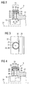
- FIG. 2 Next is in FIG. 2 in a side wall 34 of the circumferential groove 27, a channel opening 35 is provided, via which a hydraulic means of the drive device 21 for pressing the adjusting ring 28 to the pin 26 is possible.
- the required connection cables are in FIG. 2 not shown.
- FIG. 3 The plan view of an uncovered crown toothing in section 23 shows FIG. 3 , wherein identical features are provided with identical reference numerals.
- FIG. 2 alternative embodiment, which in FIG. 4 is shown, instead of a unilaterally arranged adjusting ring 28, a further adjusting ring 28 may be provided, such that between two belonging to a drive device adjusting rings 28, the pins 26 of the compressor blades 19 are arranged and thus toothed on both sides.
- two grooves 27 are provided on both sides of the bores 25, in each of which one of the two adjusting rings 28 is arranged.
- the bores 25 and thus also the pins 26 can be arranged centrally in only then a wider circumferential groove.
- the two adjusting rings 28 associated with a drive device 21 are then simultaneously rotated in opposite directions.
- FIG. 4 shown spring elements 36 to be arranged even with a drive device 21 with only one adjusting ring 28.
- the hydraulic contact pressure for each adjusting ring 28 of a drive device 21, in the two oppositely rotatable adjusting rings 28 according to FIG. 4 are provided.
- the drive shown in the figures is not only suitable for adjusting inlet guide vanes of a compressor, but of course also for adjusting guide vanes of subsequent compressor stages, which in modern gas turbines also around their longitudinal axis 31, which coincides with the radial direction with respect to the machine axis 24, are pivotally mounted.
- the invention relates to a drive device 21 for pivoting adjustable blades of a turbomachine, with an enclosed by a blade carrier 22 annular flow channel portion 23 which extends along the central axis 24 of the blade carrier 22 and are provided in the radiated to form a ring blades, said Blades are each pivotable about their longitudinal axis 31 and each have a at least in the blade carrier 22 extending pins 26 which are coupled to at least one of the blade carrier 22 encompassing adjusting ring 28.
- the pins 26, the adjusting ring 28 and, if applicable, their coupling be shielded in total, ie jointly.
Landscapes
- Engineering & Computer Science (AREA)
- Mechanical Engineering (AREA)
- General Engineering & Computer Science (AREA)
- Structures Of Non-Positive Displacement Pumps (AREA)
Priority Applications (1)
| Application Number | Priority Date | Filing Date | Title |
|---|---|---|---|
| EP10001723A EP2362071A1 (fr) | 2010-02-19 | 2010-02-19 | Dispositif d'entraînement pour le pivotement d'aubes réglables d'une turbomachine |
Applications Claiming Priority (1)
| Application Number | Priority Date | Filing Date | Title |
|---|---|---|---|
| EP10001723A EP2362071A1 (fr) | 2010-02-19 | 2010-02-19 | Dispositif d'entraînement pour le pivotement d'aubes réglables d'une turbomachine |
Publications (1)
| Publication Number | Publication Date |
|---|---|
| EP2362071A1 true EP2362071A1 (fr) | 2011-08-31 |
Family
ID=42122792
Family Applications (1)
| Application Number | Title | Priority Date | Filing Date |
|---|---|---|---|
| EP10001723A Withdrawn EP2362071A1 (fr) | 2010-02-19 | 2010-02-19 | Dispositif d'entraînement pour le pivotement d'aubes réglables d'une turbomachine |
Country Status (1)
| Country | Link |
|---|---|
| EP (1) | EP2362071A1 (fr) |
Citations (14)
| Publication number | Priority date | Publication date | Assignee | Title |
|---|---|---|---|---|
| BE623280A (fr) * | ||||
| DE1024199B (de) * | 1953-10-09 | 1958-02-13 | Sulzer Ag | Mehrstufige Axialturbomaschine |
| GB952870A (en) * | 1960-03-31 | 1964-03-18 | Louis Rene Corvisier | Improvements in or relating to variable-pitch control devices for bladed impellers and diffusers of blowers, compressors or like machines |
| GB1466613A (en) | 1973-09-07 | 1977-03-09 | Nissan Motor | Guide vane control for an automobile gas turbine engine |
| GB1505858A (en) * | 1976-12-08 | 1978-03-30 | Secr Defence | Axial flow rotary machines |
| EP0636766A1 (fr) * | 1993-07-28 | 1995-02-01 | Societe Nationale D'etude Et De Construction De Moteurs D'aviation, "S.N.E.C.M.A." | Stator de turbomachine à aubes pivotantes et anneau de commande |
| US5549448A (en) | 1995-02-08 | 1996-08-27 | United Technolgies Corporation | Variable stator vane linkage system and method |
| US6039534A (en) * | 1998-09-21 | 2000-03-21 | Northern Research And Engineering Corp | Inlet guide vane assembly |
| GB2367595A (en) * | 2000-08-08 | 2002-04-10 | Rolls Royce Plc | Actuator mechanism for variable angle vanes having a unison ring directly connected to a vane spindle |
| EP1524413A2 (fr) | 2003-10-15 | 2005-04-20 | United Technologies Corporation | Manchon de palier en électro-graphite pour une aube variable |
| EP1818509A1 (fr) * | 2006-02-09 | 2007-08-15 | Siemens Aktiengesellschaft | Agencement d'aubes de guidage |
| EP1974973A1 (fr) * | 2007-03-30 | 2008-10-01 | Kunststoff Schwanden AG | Store pour véhicules automobiles |
| FR2914944A1 (fr) * | 2007-04-13 | 2008-10-17 | Snecma Sa | Calage variable d'aubes de compresseur dans une turbomachine |
| EP2053204A2 (fr) * | 2007-10-22 | 2009-04-29 | United Technologies Corporation | Moteur à turbine à gaz avec aubes variables |
-
2010
- 2010-02-19 EP EP10001723A patent/EP2362071A1/fr not_active Withdrawn
Patent Citations (14)
| Publication number | Priority date | Publication date | Assignee | Title |
|---|---|---|---|---|
| BE623280A (fr) * | ||||
| DE1024199B (de) * | 1953-10-09 | 1958-02-13 | Sulzer Ag | Mehrstufige Axialturbomaschine |
| GB952870A (en) * | 1960-03-31 | 1964-03-18 | Louis Rene Corvisier | Improvements in or relating to variable-pitch control devices for bladed impellers and diffusers of blowers, compressors or like machines |
| GB1466613A (en) | 1973-09-07 | 1977-03-09 | Nissan Motor | Guide vane control for an automobile gas turbine engine |
| GB1505858A (en) * | 1976-12-08 | 1978-03-30 | Secr Defence | Axial flow rotary machines |
| EP0636766A1 (fr) * | 1993-07-28 | 1995-02-01 | Societe Nationale D'etude Et De Construction De Moteurs D'aviation, "S.N.E.C.M.A." | Stator de turbomachine à aubes pivotantes et anneau de commande |
| US5549448A (en) | 1995-02-08 | 1996-08-27 | United Technolgies Corporation | Variable stator vane linkage system and method |
| US6039534A (en) * | 1998-09-21 | 2000-03-21 | Northern Research And Engineering Corp | Inlet guide vane assembly |
| GB2367595A (en) * | 2000-08-08 | 2002-04-10 | Rolls Royce Plc | Actuator mechanism for variable angle vanes having a unison ring directly connected to a vane spindle |
| EP1524413A2 (fr) | 2003-10-15 | 2005-04-20 | United Technologies Corporation | Manchon de palier en électro-graphite pour une aube variable |
| EP1818509A1 (fr) * | 2006-02-09 | 2007-08-15 | Siemens Aktiengesellschaft | Agencement d'aubes de guidage |
| EP1974973A1 (fr) * | 2007-03-30 | 2008-10-01 | Kunststoff Schwanden AG | Store pour véhicules automobiles |
| FR2914944A1 (fr) * | 2007-04-13 | 2008-10-17 | Snecma Sa | Calage variable d'aubes de compresseur dans une turbomachine |
| EP2053204A2 (fr) * | 2007-10-22 | 2009-04-29 | United Technologies Corporation | Moteur à turbine à gaz avec aubes variables |
Similar Documents
| Publication | Publication Date | Title |
|---|---|---|
| EP2362070A1 (fr) | Dispositif d'entraînement pour le pivotement d'aubes réglables d'une turbomachine | |
| EP1398463B1 (fr) | Aubes de guidage variables et turbosoufflante avec ces aubes | |
| EP1394364B1 (fr) | Turbosoufflante et son anneau de guidage | |
| DE102006004613B4 (de) | Gasturbine, die eine Abdichtstruktur aufweist | |
| EP2650490B1 (fr) | Dispositif de réglage d'aube directrice d'une turbine à gaz | |
| DE69019833T2 (de) | Turbolader mit verstellbaren Leitschaufeln. | |
| EP2209969B1 (fr) | Dispositif de suralimentation | |
| EP2960437B1 (fr) | Système d'aubes de guidage variables pour une turbine à gaz et turbine à gaz dotée d'un tel système | |
| EP3000984B1 (fr) | Dispositif de reglage d'aube directrice d'une turbine a gaz | |
| EP2386726B1 (fr) | Section de paroi de canal pour un canal d'écoulement annulaire d'une turbomachine axiale dotée d'un réglage du jeu en bout d'aube, compresseur axial et turbine à gaz associés | |
| EP2520767B1 (fr) | dispositif de correction de balourd d'un rotor d'une turbine à gaz | |
| DE4036693A1 (de) | Laufschaufelspitzenspaltbreitensteuer - vorrichtung mit mantelsegmenteinstellung durch gleichlaufring | |
| DE4028328A1 (de) | Vorrichtung zum steuern der spaltbreite zwischen den laufschaufelspitzen und einem stationaeren gehaeusemantelring eines gasturbinentriebwerks | |
| EP1508672A1 (fr) | Anneau de fixation segmenté pour une turbine | |
| DE4214775A1 (de) | Dampfturbine mit einem Drehschieber | |
| DE1011671B (de) | Radialturbomaschine mit einstellbarem Leitapparat | |
| DE102015220333A1 (de) | Vorrichtung zur Einstellung eines Spaltes zwischen dem Gehäuse eines Laufrades und dem Laufrad in einem Radialverdichter und eine Turbomaschine | |
| EP0173803B1 (fr) | Machine d'écoulement | |
| EP2730751B1 (fr) | Dispositif de réglage d'aubes directrices d'une turbine à gaz | |
| EP3095957B1 (fr) | Disque de rotor pour compresseur | |
| WO2018162306A1 (fr) | Turbine comprenant des aubes directrices ajustables | |
| DE10303340A1 (de) | Kühleinrichtung | |
| DE1286333B (de) | Ringfoermige Leitvorrichtung fuer Gasturbinentriebwerke mit axialer Stroemung | |
| EP3094863B1 (fr) | Ensemble de paliers pour engrenage planétaire d'éolienne | |
| EP2816198B1 (fr) | Ensemble d'aube directrice, aube directrice et procédé de montage d'une aube directrice |
Legal Events
| Date | Code | Title | Description |
|---|---|---|---|
| PUAI | Public reference made under article 153(3) epc to a published international application that has entered the european phase |
Free format text: ORIGINAL CODE: 0009012 |
|
| AK | Designated contracting states |
Kind code of ref document: A1 Designated state(s): AT BE BG CH CY CZ DE DK EE ES FI FR GB GR HR HU IE IS IT LI LT LU LV MC MK MT NL NO PL PT RO SE SI SK SM TR |
|
| AX | Request for extension of the european patent |
Extension state: AL BA RS |
|
| STAA | Information on the status of an ep patent application or granted ep patent |
Free format text: STATUS: THE APPLICATION IS DEEMED TO BE WITHDRAWN |
|
| 18D | Application deemed to be withdrawn |
Effective date: 20120301 |