EP2362077A2 - Moteur à combustion interne - Google Patents
Moteur à combustion interne Download PDFInfo
- Publication number
- EP2362077A2 EP2362077A2 EP11001203A EP11001203A EP2362077A2 EP 2362077 A2 EP2362077 A2 EP 2362077A2 EP 11001203 A EP11001203 A EP 11001203A EP 11001203 A EP11001203 A EP 11001203A EP 2362077 A2 EP2362077 A2 EP 2362077A2
- Authority
- EP
- European Patent Office
- Prior art keywords
- fuel
- mixture
- mixing device
- combustion engine
- prechamber
- Prior art date
- Legal status (The legal status is an assumption and is not a legal conclusion. Google has not performed a legal analysis and makes no representation as to the accuracy of the status listed.)
- Withdrawn
Links
- 238000002485 combustion reaction Methods 0.000 title claims description 27
- 239000000203 mixture Substances 0.000 claims abstract description 69
- 239000000446 fuel Substances 0.000 claims abstract description 46
- 238000002156 mixing Methods 0.000 claims abstract description 21
- 239000007789 gas Substances 0.000 description 27
- 239000004071 soot Substances 0.000 description 13
- 230000000694 effects Effects 0.000 description 5
- 238000004140 cleaning Methods 0.000 description 4
- 230000015572 biosynthetic process Effects 0.000 description 3
- 230000007423 decrease Effects 0.000 description 3
- QVGXLLKOCUKJST-UHFFFAOYSA-N atomic oxygen Chemical compound [O] QVGXLLKOCUKJST-UHFFFAOYSA-N 0.000 description 2
- 230000008901 benefit Effects 0.000 description 2
- 230000003111 delayed effect Effects 0.000 description 2
- 239000003344 environmental pollutant Substances 0.000 description 2
- 238000012423 maintenance Methods 0.000 description 2
- 239000001301 oxygen Substances 0.000 description 2
- 229910052760 oxygen Inorganic materials 0.000 description 2
- 231100000719 pollutant Toxicity 0.000 description 2
- 210000002023 somite Anatomy 0.000 description 2
- 238000012360 testing method Methods 0.000 description 2
- 239000004215 Carbon black (E152) Substances 0.000 description 1
- 206010053615 Thermal burn Diseases 0.000 description 1
- 230000001133 acceleration Effects 0.000 description 1
- 230000001419 dependent effect Effects 0.000 description 1
- 238000011049 filling Methods 0.000 description 1
- 238000009363 floriculture Methods 0.000 description 1
- 230000009661 flower growth Effects 0.000 description 1
- 230000012010 growth Effects 0.000 description 1
- 229930195733 hydrocarbon Natural products 0.000 description 1
- 150000002430 hydrocarbons Chemical class 0.000 description 1
- 238000011835 investigation Methods 0.000 description 1
- 230000000737 periodic effect Effects 0.000 description 1
- 238000003976 plant breeding Methods 0.000 description 1
- 238000002360 preparation method Methods 0.000 description 1
- 238000000746 purification Methods 0.000 description 1
Images


Classifications
-
- F—MECHANICAL ENGINEERING; LIGHTING; HEATING; WEAPONS; BLASTING
- F02—COMBUSTION ENGINES; HOT-GAS OR COMBUSTION-PRODUCT ENGINE PLANTS
- F02B—INTERNAL-COMBUSTION PISTON ENGINES; COMBUSTION ENGINES IN GENERAL
- F02B19/00—Engines characterised by precombustion chambers
- F02B19/10—Engines characterised by precombustion chambers with fuel introduced partly into pre-combustion chamber, and partly into cylinder
-
- F—MECHANICAL ENGINEERING; LIGHTING; HEATING; WEAPONS; BLASTING
- F02—COMBUSTION ENGINES; HOT-GAS OR COMBUSTION-PRODUCT ENGINE PLANTS
- F02B—INTERNAL-COMBUSTION PISTON ENGINES; COMBUSTION ENGINES IN GENERAL
- F02B19/00—Engines characterised by precombustion chambers
- F02B19/12—Engines characterised by precombustion chambers with positive ignition
-
- F—MECHANICAL ENGINEERING; LIGHTING; HEATING; WEAPONS; BLASTING
- F02—COMBUSTION ENGINES; HOT-GAS OR COMBUSTION-PRODUCT ENGINE PLANTS
- F02D—CONTROLLING COMBUSTION ENGINES
- F02D19/00—Controlling engines characterised by their use of non-liquid fuels, pluralities of fuels, or non-fuel substances added to the combustible mixtures
- F02D19/02—Controlling engines characterised by their use of non-liquid fuels, pluralities of fuels, or non-fuel substances added to the combustible mixtures peculiar to engines working with gaseous fuels
- F02D19/021—Control of components of the fuel supply system
- F02D19/023—Control of components of the fuel supply system to adjust the fuel mass or volume flow
-
- F—MECHANICAL ENGINEERING; LIGHTING; HEATING; WEAPONS; BLASTING
- F02—COMBUSTION ENGINES; HOT-GAS OR COMBUSTION-PRODUCT ENGINE PLANTS
- F02M—SUPPLYING COMBUSTION ENGINES IN GENERAL WITH COMBUSTIBLE MIXTURES OR CONSTITUENTS THEREOF
- F02M21/00—Apparatus for supplying engines with non-liquid fuels, e.g. gaseous fuels stored in liquid form
- F02M21/02—Apparatus for supplying engines with non-liquid fuels, e.g. gaseous fuels stored in liquid form for gaseous fuels
- F02M21/04—Gas-air mixing apparatus
- F02M21/047—Venturi mixer
-
- Y—GENERAL TAGGING OF NEW TECHNOLOGICAL DEVELOPMENTS; GENERAL TAGGING OF CROSS-SECTIONAL TECHNOLOGIES SPANNING OVER SEVERAL SECTIONS OF THE IPC; TECHNICAL SUBJECTS COVERED BY FORMER USPC CROSS-REFERENCE ART COLLECTIONS [XRACs] AND DIGESTS
- Y02—TECHNOLOGIES OR APPLICATIONS FOR MITIGATION OR ADAPTATION AGAINST CLIMATE CHANGE
- Y02T—CLIMATE CHANGE MITIGATION TECHNOLOGIES RELATED TO TRANSPORTATION
- Y02T10/00—Road transport of goods or passengers
- Y02T10/10—Internal combustion engine [ICE] based vehicles
- Y02T10/12—Improving ICE efficiencies
-
- Y—GENERAL TAGGING OF NEW TECHNOLOGICAL DEVELOPMENTS; GENERAL TAGGING OF CROSS-SECTIONAL TECHNOLOGIES SPANNING OVER SEVERAL SECTIONS OF THE IPC; TECHNICAL SUBJECTS COVERED BY FORMER USPC CROSS-REFERENCE ART COLLECTIONS [XRACs] AND DIGESTS
- Y02—TECHNOLOGIES OR APPLICATIONS FOR MITIGATION OR ADAPTATION AGAINST CLIMATE CHANGE
- Y02T—CLIMATE CHANGE MITIGATION TECHNOLOGIES RELATED TO TRANSPORTATION
- Y02T10/00—Road transport of goods or passengers
- Y02T10/10—Internal combustion engine [ICE] based vehicles
- Y02T10/30—Use of alternative fuels, e.g. biofuels
Definitions
- This invention relates to a spark-ignited internal combustion engine according to the preamble of claim 1.
- spark-ignition internal combustion engines are equipped with an antechamber.
- the main combustion chamber receives a lean fuel-air mixture, and a small pre-chamber is used to ignite a very rich mixture of (at least nearly) pure fuel by means of a spark source, which in turn ignites and burns the lean mixture in the main combustion chamber.
- the rich mixture that enters the pre-chamber sometimes forms soot (unburned hydrocarbon) because there is not enough oxygen available.
- soot unburned hydrocarbon
- the key cause of this problem is that a very rich mixture or pure fuel flows into the prechamber.
- there is not enough oxygen for proper combustion inside the antechamber Although it is expressly intended to have a rich mixture in the prechamber, it is undesirable for soot to form in the prechamber. Because soot increases the pollutant emissions of the engine, which is not at all in the interest of the customer.
- This soot formation can be reduced by letting less pure fuel flow into the prechamber. But this impairs the flame spread from the prechamber to the main combustion chamber, resulting in delayed ignition which in turn degrades the combustion of the lean mixture. The result can be a significantly reduced engine performance.
- the pre-chamber is designed for a certain optimum volume flow, so that a reduced volume flow can have a significant effect on the combustion, more precisely: the flame propagation.
- the ignition may be delayed, and the engine power may decrease overall.
- a lean fuel-air mixture according to the invention can be described by a lambda range of about 1.5 to 2.5; a very rich fuel-air mixture can be described by a lambda range of about 0.1 to 1.2.
- the rich mixture may have a lambda value of 0.9.
- the lean mixture may have a lambda value of 1.9.
- the invention also allows varying the saturation of the mixture (the ratio of fuel to air), it can be used to simulate engine operation with different types of fuel, fuel mixtures, and ratios whereby the time for testing a new engine with another fuel, etc. can be shortened.
- the engine exhaust gases are often used as heat and CO 2 source for plant breeding, especially for floriculture, by catching the exhaust gas in a greenhouse. If the exhaust gas contains soot, soot also gets into the greenhouse, which is undesirable because it inhibits the growth of flowers and other plants.
- soot content of the engine exhaust By reducing the soot content of the engine exhaust, a better and less polluted greenhouse effect can be achieved for flower nurseries that use engine exhaust to produce a greenhouse effect to promote flower growth in a controlled environment.
- the invention also helps to meet strict emissions standards and supports efforts to greener the environment.
- the invention helps to reduce the cost of purifying the exhaust gas and reducing the impact of the exhaust gases on the products that depend on the exhaust of the engine. It also reduces the need for the use of expensive emission control systems.
- Cost savings for maintenance and downtime Apart from the costs of cleaning the exhaust gas, the other possible soot reduction options can also affect the replacement of many different parts, which would otherwise require regular cleaning of the antechambers.
- the invention basically uses the pressure difference and the Bernouill principle.
- the idea concerns the mixing of two gases in a convergent-straight-divergent (KGD) nozzle (Venturi nozzle).
- the Venturi nozzle has a convergent, a straight (in the throat section) and a divergent section for the flow of the lean mixture.
- the rich mixture is mixed in the required proportion by means of fuel supply holes arranged around the entire neck portion (straight portion).
- the proportion or mixture ratio can be controlled.
- the finished mixture is channeled through hoses and connectors into the antechambers of all cylinder heads, reducing soot emissions by up to 50%.
- the lean mixture flow through the nozzle creates a pressure drop in the throat, in the circumference of which are evenly spaced radial holes.
- This pressure drop basically promotes the flow or suction of pure fuel and thus the mixing of the gases in the divergent section and in the remainder of the fuel flow path.
- the pressure difference between the two gas streams can be varied.
- the amount of air drawn into the engine increases. Due to the increase in the flow rate is preferably to ensure that the supply pressure of the pure fuel is also varied accordingly. Failure to do so could affect the saturation of the mixture flowing into the antechamber.
- a control circuit or loop may be used which ensures that the pressure differential between the two flows is controlled so that the saturation of the pre-chamber mixture remains the same.
- the mixture preparation device is arranged at a position directly behind a charge air cooler (turbo bypass), the pressure drop of the lean mixture reaching the nozzle can be reduced. This can be crucial because the more pressure drops, the lower the potential pressure difference that is possible between the two flows, causing the two gases to be mixed insufficiently.
- the convergent-straight divergent nozzle may be disposed in a housing in which the convergent-straight divergent nozzle is well secured and fully held in place.
- the housing may be used to direct the clean gas supplied to the engine into an annulus formed around the nozzle, particularly in the straight section or throat of the nozzle, where radial holes are preferably equally spaced along the circumference (360 °) are to allow a proper mixing.
- a suitable seal can be made along the annular region so that no gases can escape.
- the housing when collecting the gas mixture (mixture of pure fuel and lean mixture), the housing also helps from the nozzle and, moreover, feeds it to a T-piece, which finally sends the gases into the prechamber via hoses and piping.
- the dimensioning of the nozzle as well as of the pipes and hoses depends on the flow velocity of the gases. It should be ensured that the flow velocity is below Mach 1 (speed of sound), so that the effect of the convergent-straight divergent nozzle does not reverse.
- Mach 1 speed of sound
- Preferred internal combustion engines are gasoline engines (preferably gas engines), in particular of stationary design.
- FIG. 1 shows those parts of a spark-ignition internal combustion engine 1, which are relevant to the present invention. Other parts of the engine 1 familiar to those skilled in the art are not shown.
- a prechamber 2 is connected to the combustion chamber 3.
- a spark source 4 A lean fuel-air mixture is directed into a charge air cooler 13 by a turbocharger (not shown). A portion of this mixture is passed via a line 17 in the main combustion chamber 3. Another part is passed via the second fuel line 6 to a mixing device 7. Via a control valve 14 (which is controlled by the control system 12) and a first fuel line 5 pure fuel is fed into the mixing device 7. The mixture leaving the mixing device 7 becomes passed via a line 18 in the pre-chamber 2. In this line 18, a check valve or one-way valve 15 is arranged.
- the conduit 17 is provided with a plurality of sensors 16 which measure the pressure from the intake pipe (P 1 ), the throttle position signal ( ⁇ ) and the temperature from the intake pipe (T 1 ).
- an O x sensor 20 is arranged in the exhaust pipe 19.
- the measured signals are sent to a database connected to the control system 12.
- the control system 12 performs a control loop control of the valve 14 based on the values supplied by the sensors 16, 20 and the setpoints stored in the database.
- FIG. 2 shows the mixing device 7 in greater detail.
- the mixing device 7 comprises a Venturi nozzle.
- a batch of the lean mixture from the intake manifold is directed into the convergent section 8 of the venturi.
- Pure fuel or a very rich fuel-air mixture will pass through several holes 9 (of which only two in FIG. 2
- the dilute charge is directed to the antechamber 2 via the divergent section 11 of the venturi.
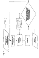
- FIG. 3 One possible closed-loop control scheme with which the control unit 12 can maintain a desired lambda value is shown in FIG. 3 shown. It is checked whether the Ahgasmess uncomfortable (for example, the supplied by the sensor 20 NO x word) comply with certain specifications (which are included in the database). If this is not the case, the amount of pure fuel, which is passed via the line 5 to the mixing device 7, adjusted. Other control data is provided by the sensors 16.
- Ahgasmess uncomfortable for example, the supplied by the sensor 20 NO x word
- certain specifications which are included in the database
Landscapes
- Engineering & Computer Science (AREA)
- Chemical & Material Sciences (AREA)
- Combustion & Propulsion (AREA)
- Mechanical Engineering (AREA)
- General Engineering & Computer Science (AREA)
- Chemical Kinetics & Catalysis (AREA)
- General Chemical & Material Sciences (AREA)
- Oil, Petroleum & Natural Gas (AREA)
- Combustion Methods Of Internal-Combustion Engines (AREA)
Applications Claiming Priority (2)
| Application Number | Priority Date | Filing Date | Title |
|---|---|---|---|
| AT932010 | 2010-02-22 | ||
| AT0019510U AT11892U1 (de) | 2010-02-22 | 2010-03-25 | Verbrennungsmotor |
Publications (2)
| Publication Number | Publication Date |
|---|---|
| EP2362077A2 true EP2362077A2 (fr) | 2011-08-31 |
| EP2362077A3 EP2362077A3 (fr) | 2016-08-17 |
Family
ID=43825225
Family Applications (1)
| Application Number | Title | Priority Date | Filing Date |
|---|---|---|---|
| EP11001203.6A Withdrawn EP2362077A3 (fr) | 2010-02-22 | 2011-02-15 | Moteur à combustion interne |
Country Status (2)
| Country | Link |
|---|---|
| EP (1) | EP2362077A3 (fr) |
| AT (1) | AT11892U1 (fr) |
Cited By (3)
| Publication number | Priority date | Publication date | Assignee | Title |
|---|---|---|---|---|
| EP3612726A4 (fr) * | 2017-04-21 | 2021-01-13 | Scania CV AB | Moteur à gaz, procédé de fonctionnement d'un moteur à gaz et ensemble générateur |
| US11258650B2 (en) | 2017-06-30 | 2022-02-22 | Huawei Technologies Co., Ltd. | Communication method, communications apparatus, and storage medium |
| CN114382585A (zh) * | 2020-10-20 | 2022-04-22 | 广州汽车集团股份有限公司 | 主动预燃室燃料供给系统 |
Families Citing this family (2)
| Publication number | Priority date | Publication date | Assignee | Title |
|---|---|---|---|---|
| DE102015206074B4 (de) * | 2015-04-02 | 2019-12-19 | Mtu Friedrichshafen Gmbh | Brennkraftmaschine und Verfahren zum Betreiben einer Brennkraftmaschine |
| DE102018222525B4 (de) * | 2018-12-20 | 2020-09-03 | Mtu Friedrichshafen Gmbh | Verfahren zum Betreiben einer Brennkraftmaschine und Brennkraftmaschine zur Durchführung eines solchen Verfahrens |
Family Cites Families (5)
| Publication number | Priority date | Publication date | Assignee | Title |
|---|---|---|---|---|
| US3659564A (en) * | 1968-11-01 | 1972-05-02 | Toyoda Chuo Kenkyusho Kk | Internal combustion engine with sub-combustion chamber |
| JP3194619B2 (ja) * | 1992-05-21 | 2001-07-30 | ヤンマーディーゼル株式会社 | 6bガス用副室式ガス機関 |
| JP2868421B2 (ja) * | 1994-10-24 | 1999-03-10 | ヤンマーディーゼル株式会社 | 副室式ガス機関の混合気副室供給機構 |
| DE10133190A1 (de) * | 2001-07-07 | 2003-01-16 | Deutz Ag | Vorkammeranreicherung |
| DE10356192A1 (de) * | 2003-12-02 | 2005-07-07 | Deutz Ag | Gasmotor |
-
2010
- 2010-03-25 AT AT0019510U patent/AT11892U1/de not_active IP Right Cessation
-
2011
- 2011-02-15 EP EP11001203.6A patent/EP2362077A3/fr not_active Withdrawn
Non-Patent Citations (1)
| Title |
|---|
| None |
Cited By (5)
| Publication number | Priority date | Publication date | Assignee | Title |
|---|---|---|---|---|
| EP3612726A4 (fr) * | 2017-04-21 | 2021-01-13 | Scania CV AB | Moteur à gaz, procédé de fonctionnement d'un moteur à gaz et ensemble générateur |
| US10968866B2 (en) | 2017-04-21 | 2021-04-06 | Scania Cv Ab | Gas engine, method for operating a gas engine and generator set |
| US11258650B2 (en) | 2017-06-30 | 2022-02-22 | Huawei Technologies Co., Ltd. | Communication method, communications apparatus, and storage medium |
| CN114382585A (zh) * | 2020-10-20 | 2022-04-22 | 广州汽车集团股份有限公司 | 主动预燃室燃料供给系统 |
| US11788458B2 (en) | 2020-10-20 | 2023-10-17 | Guangzhou Automobile Group Co., Ltd. | Fuel supply system for active pre-combustor |
Also Published As
| Publication number | Publication date |
|---|---|
| EP2362077A3 (fr) | 2016-08-17 |
| AT11892U1 (de) | 2011-06-15 |
Similar Documents
| Publication | Publication Date | Title |
|---|---|---|
| DE60223229T2 (de) | Vorrichtung zur zuführung von rückgeführtem abgas | |
| DE112018006328B4 (de) | Reduktionsmittelzufuhrsysteme und Verfahren | |
| DE2153816A1 (de) | Verfahren zum Vermischen von flussi gern Kraftstoff mit Luft und Einrichtung zum Durchfuhren des Verfahrens | |
| DE102005013977A1 (de) | Abgasrückführsystem für ein Kraftfahrzeug und Verfahren zum Einstellen der Abgasrückführrate in einem Gasrückführsystem | |
| DE102007010557A1 (de) | System für einen virtuellen Taupunktsensor | |
| DE102007036958A1 (de) | Einblasvorrichtung für gasförmigen Kraftstoff in einen Verbrennungsmotor, zugehöriges Verfahren sowie Steuergerät | |
| DE102017117202A1 (de) | Verfahren und system zum auswählen einer stelle zur wassereinspritzung in einem motor | |
| WO2002042730A2 (fr) | Procede pour l'alimentation d'un moteur a combustion interne en gaz de combustion conditionne, dispositif pour l'execution de ce procede, procede pour la determination des quantites de polluants dans les gaz d'echappement d'un moteur a combustion interne et dispositif pour l'execution de ce procede | |
| EP2362077A2 (fr) | Moteur à combustion interne | |
| DE69816579T2 (de) | Brennkraftmaschine mit NOx-Katalysator für Magergemischverbrennung | |
| DE102017107233B4 (de) | Abgasreinigungssystem für verbrennungsmotor | |
| DE69712842T2 (de) | Vorrichtung zur Steuerung einer Brennkraftmaschine | |
| DE112011105552T5 (de) | Steuersystem für eine Multikraftstoffbrennkraftmaschine | |
| DE4325307A1 (de) | Verfahren zur Steuerung der Kraftstoffzufuhr bei einer gemischverdichtenden Brennkraftmaschine | |
| DE2310056A1 (de) | Verfahren zur regelung des zugefuehrten kraftstoff-luft-gemisches bei verbrennungsmotoren | |
| WO2006066836A1 (fr) | Procede de production d'un flux de gaz d'echappement de combustion chauds a temperature ajustable, equipement pour mettre ledit procede en oeuvre et utilisation des gaz d'echappement de combustion pour vieillissement cible de pots catalytiques | |
| DE19814972C2 (de) | Verfahren und Vorrichtung zum Messen einer in einem Strömungskanal zu einer Maschine oder von einer Maschine strömenden Fluidströmung | |
| DE102004030614B4 (de) | Regelvorrichtung für Kraftstoff/Luft-Verhältnis für Mehrzylindermotor | |
| DE69616589T2 (de) | System zum optimieren des kraftstoffverbrauchs sowie zur reduzierung des kohlendioxydsausstosses mittels der kompensierung des luftunterdrucks durch flüssigkeit | |
| DE10018308B4 (de) | Verfahren zur Regelung des Anteils der einer Brennkraftmaschine rückgeführten Abgasmenge | |
| DE102018106545A1 (de) | Abgassystem für ein kraftfahrzeug | |
| DE102004053808A1 (de) | Luft/Kraftstoff-Verhältnis-Regelungsvorrichtung für einen Verbrennungsmotor | |
| DE102017130403A1 (de) | Hybrides verbrennungssystem und verfahren dafür | |
| DE10234849A1 (de) | Verfahren, Computerprogramm und Steuer- und/oder Regelgerät zum Betreiben einer Brennkraftmaschine, sowie Brennkraftmaschine | |
| DE2807641A1 (de) | Auspuffgas-reinigungsvorrichtung |
Legal Events
| Date | Code | Title | Description |
|---|---|---|---|
| PUAI | Public reference made under article 153(3) epc to a published international application that has entered the european phase |
Free format text: ORIGINAL CODE: 0009012 |
|
| AK | Designated contracting states |
Kind code of ref document: A2 Designated state(s): AL AT BE BG CH CY CZ DE DK EE ES FI FR GB GR HR HU IE IS IT LI LT LU LV MC MK MT NL NO PL PT RO RS SE SI SK SM TR |
|
| AX | Request for extension of the european patent |
Extension state: BA ME |
|
| PUAL | Search report despatched |
Free format text: ORIGINAL CODE: 0009013 |
|
| AK | Designated contracting states |
Kind code of ref document: A3 Designated state(s): AL AT BE BG CH CY CZ DE DK EE ES FI FR GB GR HR HU IE IS IT LI LT LU LV MC MK MT NL NO PL PT RO RS SE SI SK SM TR |
|
| AX | Request for extension of the european patent |
Extension state: BA ME |
|
| RIC1 | Information provided on ipc code assigned before grant |
Ipc: F02D 19/02 20060101AFI20160708BHEP Ipc: F02B 19/12 20060101ALI20160708BHEP Ipc: F02M 21/04 20060101ALI20160708BHEP |
|
| STAA | Information on the status of an ep patent application or granted ep patent |
Free format text: STATUS: THE APPLICATION HAS BEEN PUBLISHED |
|
| STAA | Information on the status of an ep patent application or granted ep patent |
Free format text: STATUS: THE APPLICATION IS DEEMED TO BE WITHDRAWN |
|
| 18D | Application deemed to be withdrawn |
Effective date: 20170218 |