EP2362081B1 - Système de pressurisation de compartiment de palier et système de ventilation à arbre - Google Patents
Système de pressurisation de compartiment de palier et système de ventilation à arbre Download PDFInfo
- Publication number
- EP2362081B1 EP2362081B1 EP11250168.9A EP11250168A EP2362081B1 EP 2362081 B1 EP2362081 B1 EP 2362081B1 EP 11250168 A EP11250168 A EP 11250168A EP 2362081 B1 EP2362081 B1 EP 2362081B1
- Authority
- EP
- European Patent Office
- Prior art keywords
- air
- gas turbine
- turbine engine
- shaft
- centrifugal compressor
- Prior art date
- Legal status (The legal status is an assumption and is not a legal conclusion. Google has not performed a legal analysis and makes no representation as to the accuracy of the status listed.)
- Active
Links
Images
Classifications
-
- F—MECHANICAL ENGINEERING; LIGHTING; HEATING; WEAPONS; BLASTING
- F02—COMBUSTION ENGINES; HOT-GAS OR COMBUSTION-PRODUCT ENGINE PLANTS
- F02C—GAS-TURBINE PLANTS; AIR INTAKES FOR JET-PROPULSION PLANTS; CONTROLLING FUEL SUPPLY IN AIR-BREATHING JET-PROPULSION PLANTS
- F02C7/00—Features, components parts, details or accessories, not provided for in, or of interest apart form groups F02C1/00 - F02C6/00; Air intakes for jet-propulsion plants
- F02C7/32—Arrangement, mounting, or driving, of auxiliaries
-
- F—MECHANICAL ENGINEERING; LIGHTING; HEATING; WEAPONS; BLASTING
- F02—COMBUSTION ENGINES; HOT-GAS OR COMBUSTION-PRODUCT ENGINE PLANTS
- F02C—GAS-TURBINE PLANTS; AIR INTAKES FOR JET-PROPULSION PLANTS; CONTROLLING FUEL SUPPLY IN AIR-BREATHING JET-PROPULSION PLANTS
- F02C6/00—Plural gas-turbine plants; Combinations of gas-turbine plants with other apparatus; Adaptations of gas-turbine plants for special use
- F02C6/04—Gas-turbine plants providing heated or pressurised working fluid for other apparatus, e.g. without mechanical power output
- F02C6/06—Gas-turbine plants providing heated or pressurised working fluid for other apparatus, e.g. without mechanical power output providing compressed gas
- F02C6/08—Gas-turbine plants providing heated or pressurised working fluid for other apparatus, e.g. without mechanical power output providing compressed gas the gas being bled from the gas-turbine compressor
Definitions
- the present invention relates generally to gas turbine engines, and more particularly, to a system for supplying buffer air and ventilation air to the bearing compartments and shaft(s) in gas turbine engines.
- one shaft supports the rotors of a low pressure compressor and a low pressure turbine and another shaft supports the rotors of a high pressure compressor and a high pressure turbine.
- each of the shafts is supported by bearings, and each bearing is lubricated by a forced lubrication system which circulates lubricating oil fed by a pump.
- high pressure air is drawn from the high pressure compressor and is conducted to the exterior of the oil seals of the bearing compartments to keep the interior of the bearing compartments at a lower pressure than its immediate surroundings.
- This pressure differential prevents the lubricating oil from leaking out of the bearing compartments.
- high pressure buffer air drawn from the high pressure compressor is utilized because at least one of the bearing compartments is located in a high pressure environment where buffer air from the low pressure compressor would not provide adequate compartment pressurization at low power engine operating conditions.
- buffer air drawn from the high pressure compressor is excessively hot and requires cooling at higher power engine operating conditions. Therefore, a dedicated cooler is required to lower the temperature of the buffer air. This cooler adds additional weight to the engine and can be difficult to package especially in smaller engine models.
- US 5,039,281 discloses an aircraft having a gas turbine engine, in which a compressor is driven by the main drive shaft of the gas turbine engine via an accessory gear box.
- the auxiliary compressor receives pre-compressed air from the engine compressor and supplies the compressed air to the environmental control system of the aircraft.
- the present invention provides a gas turbine engine, comprising: a shaft, a fan section, a low pressure compressor section, and at least one bearing compartment; an accessory gearbox connected to the shaft, the accessory gearbox being driven by the shaft and adapted to mechanically drive one or more engine accessories; and a centrifugal compressor driven by the accessory gearbox during operation of the gas turbine engine for receiving a bleed air and compressing the bleed air to produce the buffer air and/or the ventilation air the centrifugal compressor being configured to compress air from the fan section and/or the low pressure compressor section, wherein the compressed bleed air is communicated from the centrifugal compressor to the shaft and/or the at least one bearing compartment.
- the present invention provides a method of providing air from at least one of a low pressure compressor section and a fan section of a gas turbine engine to at least one of a bearing compartment and a shaft within the gas turbine engine, comprising: bleeding air from the at least one of the low pressure compressor section and the fan section to a centrifugal compressor; compressing the air with the centrifugal compressor, wherein the centrifugal compressor is driven by an accessory gearbox during operation of the gas turbine engine; and communicating the air to the at least one of the bearing compartment and the shaft.
- the present application describes new pressurization and ventilation systems for bearing compartments and shafts of a gas turbine engine.
- the present application describes an assembly and a method for providing buffer and/or ventilation air to bearing compartments and/or shafts of a gas turbine engine.
- the preferred gas turbine engine described includes a dedicated centrifugal compressor that compresses bleed air from a low pressure compressor section and/or a fan section of the gas turbine engine. The compressed air is delivered to the core of the engine to buffer the bearing compartments and/or ventilate one or more shafts.
- the centrifugal compressor compresses the bleed air to a higher pressure more efficiently than traditional axial compressor arrays because it avoids the loss of kinetic energy and the throttling losses at the compressor case that are experienced with traditional axial compressor arrays.
- centrifugal compressor By utilizing the centrifugal compressor, air is drawn from the fan section and/or the low pressure compressor section and compressed to a desired optimal pressure and temperature, thereby eliminating the need for cooling within a cooler. This arrangement also reduces the likelihood of an inadequately pressurized bearing compartment at low power engine operating conditions, discussed previously.
- the flow rate and pressure ratio requirements of the centrifugal compressor are low enough to allow for a compact design that can fit within various locations such as the engine core and allow the centrifugal compressor to be integrated as an accessory to be driven by the gearbox.
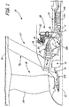
- FIG. 1 shows a schematic partial cross section of a portion of a gas turbine engine 10.
- Gas turbine engine 10 has bearing compartments 12A and 12B which house anti-friction bearings that support shafts 14A and 14B.
- Gas turbine engine 10 is defined around an engine centerline C L about which various engine sections rotate.
- FIG. 1 only a portion of gas turbine engine 10 including a rotor section 16, a fan section 18, a low pressure compressor (LPC) section 20, and a high pressure compressor (HPC) section 22 is illustrated.
- LPC low pressure compressor
- HPC high pressure compressor
- Gas turbine engine 10 is illustrated as a high bypass ratio turbofan engine with a dual spool arrangement in which fan section 18 and LPC 20 are connected to a low pressure turbine section (not shown) by rotor 16, fan drive gear system 15, and shaft 14A, and high pressure compressor section 22 is connected to a high pressure turbine section (not shown) by second shaft 14B.
- gas turbine engines and in particular turbofan engines, is well-known in the art, and therefore, detailed discussion herein is unnecessary. It should be noted, however, that engine 10 is shown in FIG. 1 merely by way of example and not limitation. The present invention is also applicable to a variety of other gas turbine engine configurations, such as a turbofan engine without fan-drive gear system and a turboprop engine, for example.
- gas turbine engine 10 includes a fan rotor 24, an outer case 26, a bypass duct 27, an inner fan case 28, an intermediate case 30, an accessory gearbox 32, a centrifugal compressor 34, and a radial drive shaft 36.
- Inner fan duct 28 and intermediate case 30 define a core compartment 38.
- the fan 24 is disposed radially inward of outer case 26 and is rotated by the low pressure turbine (not shown) through the shaft 14 and fan-drive gear system 15 to accelerate the bypass air A B through fan section 18, thereby producing a significant portion of the thrust output of engine 10.
- the primary air A P (also known as gas path air) is directed first through the low pressure compressor section 20 (which is partially bounded by intermediate case 30) and then through high pressure compressor section 22.
- accessory gearbox 32 is connected to intermediate case 30 and extends radially outward of engine centerline C L away from low pressure compressor section 20.
- the location of accessory gearbox 32 in FIG. 1 is by way of example and not limitation. In other embodiments, accessory gearbox 32 can be disposed on outer case 26, inner fan case 28 or in other locations including within the core of the gas turbine engine 10.
- Accessory gearbox 32 is connected to and drives centrifugal compressor 34. More particularly, accessory gearbox 32 transfers torque from radial drive shaft 36 to centrifugal compressor 34.
- Radial drive shaft 36 is coupled to accessory gearbox 32 and extends into bearing compartment 12B (specifically called a high rotor thrust bearing compartment) to couple with and transfer torque from shaft 14B.
- Accessory gearbox 32 commonly drives various engine accessories including an electrical generator (not shown) and a main engine oil system, which is used to lubricate components of the engine including the bearings.
- Accessory gearbox 32 is specifically adapted to drive centrifugal compressor 34, which is disposed within core compartment 38. Scoops or other known devices bleed air at a lower pressure from fan section 18 and/or low pressure compressor section 20. This bleed air is directed to centrifugal compressor 34 where it is compressed to a higher pressure.
- lower pressure bleed air directed to the centrifugal compressor 34 can comprise either bypass air A B or primary air A P or a mixture of both. Primary air A P can be drawn off various stages of the low pressure compressor section 20 as desired.
- Centrifugal compressor 34 operates in a manner known in the art to compress lower pressure bleed air to a higher pressure. Operation of the centrifugal compressor causes a pressure differential that circulates the higher pressure air A to all bearing compartments including forward bearing compartments 12A and 12B and more rearward bearing compartments ( FIG. 2 ) to act as buffer air. In addition to or in alternative to being used as buffer air for the bearing compartments, higher pressure air A can be used as ventilation air to ventilate shaft 14 in a manner known in the art.
- Utilization of centrifugal compressor 34 allows higher pressure A to be compressed to a desired optimal pressure and temperature to provide adequate pressurization to bearing compartments 12A and 12B to prevent oil leakage therefrom. Compressing air A to the desired optimal temperature and pressure eliminates the need for the cooling of air A within a cooler, thereby reducing engine 10 weight and providing more design space within engine 10.
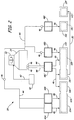
- FIG. 2 shows a schematic view of a system 39 that provides buffer air and ventilation air within gas turbine engine 10.
- System 39 includes a lower pressure location 40, lower pressure external lines or internal passages 42, higher pressure external lines or internal passages 44, metering devices 46, structures 48A-48E, bearing compartments 12A-12D surrounded by seal cavities 13A - 13F, and a secondary air flow 50.
- Accessory gearbox 32 is coupled to and acts to drive centrifugal compressor 34. Scoops or other known devices bleed air at a lower pressure from lower pressure location 40 within gas turbine engine 10.
- location 40 comprises fan section 18 ( FIG. 1 ) and/or low pressure compressor section 20 ( FIG. 1 ). Bleed air is directed as air flow through lower pressure external lines or internal passages 42 to centrifugal compressor 34, which operates to compress the lower pressure bleed air to a higher pressure.
- the higher pressure air that is compressed in centrifugal compressor 34 circulates away from centrifugal compressor 34 through higher pressure external lines and internal passages 44. Higher pressure air flow branches into several flows that are directed through one or more metering devices 46, such as valves or orifices, which throttle air flow as desired.
- higher pressure air flow is directed through structures 48A-48E.
- Structures 48A-48E can variously comprise struts and/or other portions of the front center body, intermediate case, or mid-turbine frame of gas turbine engine 10.
- Higher pressure air flow passes through structures 48A-48E to provide buffer air to seal cavities 13A-13F that surround bearing compartments 12A-12D and ventilation air to shaft 14 ( FIG. 1 ).
- secondary air flow 50 continues from seal cavity 13C as ventilation air along the inner diameter of shaft 14A. Secondary air flow 50 also provides buffer air to seal cavity 13F that buffers bearing compartment 12D toward the rear of gas turbine engine 10.
Landscapes
- Engineering & Computer Science (AREA)
- Chemical & Material Sciences (AREA)
- Combustion & Propulsion (AREA)
- Mechanical Engineering (AREA)
- General Engineering & Computer Science (AREA)
- Structures Of Non-Positive Displacement Pumps (AREA)
Claims (14)
- Moteur à turbine à gaz, comprenant :un arbre (36), une section de ventilateur (18), une section de compresseur basse pression (20) et au moins un compartiment de palier (12) ;une boîte de vitesses pour accessoires (32) reliée à l'arbre, la boîte de vitesses pour accessoires étant entraînée par l'arbre et adaptée pour entraîner mécaniquement un ou plusieurs accessoires de moteur ;caractérisé parun compresseur centrifuge (34) entraîné par la boîte de vitesses pour accessoires pendant le fonctionnement du moteur à turbine à gaz pour la réception d'un air de prélèvement et la compression de l'air de prélèvement pour produire l'air intermédiaire et/ou l'air de ventilation, le compresseur centrifuge étant configuré pour compresser de l'air provenant de la section de ventilateur et/ou de la section de compresseur basse pression,dans lequel l'air de prélèvement comprimé est communiqué du compresseur centrifuge à l'arbre et/ou à l'au moins un compartiment de palier.
- Moteur à turbine à gaz selon la revendication 1, dans lequel l'air de prélèvement comprend de l'air (AP) provenant de la section de compresseur basse pression (20) du moteur à turbine à gaz.
- Moteur à turbine à gaz selon la revendication 1, dans lequel l'air de prélèvement comprend de l'air de dérivation (AB) provenant de la section de ventilateur du moteur à turbine à gaz.
- Moteur à turbine à gaz selon la revendication 1, 2 ou 3, dans lequel le moteur à turbine à gaz comprend un turboventilateur à dérivation élevée.
- Moteur à turbine à gaz selon la revendication 4, dans lequel le turboventilateur à dérivation élevée présente une bobine basse pression qui entraîne la section de ventilateur par réducteur de vitesses à engrenages.
- Moteur à turbine à gaz selon l'une quelconque des revendications 1 à 5, dans lequel l'air comprimé comprend de l'air de ventilation qui est dirigé sur l'arbre.
- Moteur à turbine à gaz selon l'une quelconque des revendications 1 à 6, dans lequel l'air comprimé comprend de l'air intermédiaire qui est dirigé sur l'au moins un compartiment de palier.
- Moteur à turbine à gaz selon la revendication 7, dans lequel l'au moins un compartiment de palier comprend trois, ou plus, compartiments de palier.
- Moteur à turbine à gaz selon l'une quelconque des revendications 1 à 8, dans lequel le compresseur centrifuge est disposé dans un compartiment central (38) du moteur à turbine à gaz.
- Procédé de fourniture d'air d'au moins l'une d'une section de compresseur basse pression (20) et d'une section de ventilateur (18) d'un moteur à turbine à gaz (10) à au moins l'un d'un compartiment de palier (12) et d'un arbre (14) dans le moteur à turbine à gaz, comprenant :le prélèvement d'air de l'au moins une de la section de compresseur basse pression et de la section de ventilateur à un compresseur centrifuge (34) ;la compression de l'air avec le compresseur centrifuge, dans lequel le compresseur centrifuge est entraîné par une boîte de vitesses pour accessoires (32) pendant le fonctionnement du moteur à turbine à gaz ; etla communication de l'air à au moins l'un du compartiment de palier et de l'arbre.
- Procédé selon la revendication 10, dans lequel le moteur à turbine à gaz comprend un turboventilateur à dérivation élevée, de préférence dans lequel le turboventilateur à dérivation élevée présente une bobine basse pression qui entraîne la section de ventilateur à travers un réducteur de vitesses à engrenages.
- Procédé selon la revendication 10 ou 11, dans lequel l'air comprimé comprend un air de ventilation qui est dirigé sur l'arbre.
- Procédé selon la revendication 10, 11 ou 12, dans lequel l'air comprimé comprend un air intermédiaire qui est dirigé sur l'au moins un compartiment de palier.
- Procédé selon la revendication 10, 11, 12, ou 13, dans lequel le compresseur centrifuge est disposé dans un compartiment central (38) du moteur à turbine à gaz.
Applications Claiming Priority (1)
| Application Number | Priority Date | Filing Date | Title |
|---|---|---|---|
| US12/708,621 US8516828B2 (en) | 2010-02-19 | 2010-02-19 | Bearing compartment pressurization and shaft ventilation system |
Publications (2)
| Publication Number | Publication Date |
|---|---|
| EP2362081A1 EP2362081A1 (fr) | 2011-08-31 |
| EP2362081B1 true EP2362081B1 (fr) | 2016-04-20 |
Family
ID=44168069
Family Applications (1)
| Application Number | Title | Priority Date | Filing Date |
|---|---|---|---|
| EP11250168.9A Active EP2362081B1 (fr) | 2010-02-19 | 2011-02-14 | Système de pressurisation de compartiment de palier et système de ventilation à arbre |
Country Status (2)
| Country | Link |
|---|---|
| US (1) | US8516828B2 (fr) |
| EP (1) | EP2362081B1 (fr) |
Cited By (1)
| Publication number | Priority date | Publication date | Assignee | Title |
|---|---|---|---|---|
| US11846237B2 (en) | 2017-01-19 | 2023-12-19 | Rtx Corporation | Gas turbine engine with intercooled cooling air and dual towershaft accessory gearbox |
Families Citing this family (54)
| Publication number | Priority date | Publication date | Assignee | Title |
|---|---|---|---|---|
| US8381878B2 (en) * | 2009-11-12 | 2013-02-26 | United Technologies Corporation | Oil capture and bypass system |
| US8602717B2 (en) * | 2010-10-28 | 2013-12-10 | United Technologies Corporation | Compression system for turbomachine heat exchanger |
| US8967944B2 (en) * | 2011-08-29 | 2015-03-03 | United Technologies Corporation | Accessory gearbox buffer cooling air pump system |
| SG11201403008WA (en) | 2011-12-30 | 2014-09-26 | United Technologies Corp | Gas turbine engine oil buffering |
| US9004849B2 (en) | 2012-01-10 | 2015-04-14 | United Technologies Corporation | Gas turbine engine forward bearing compartment architecture |
| US9416677B2 (en) | 2012-01-10 | 2016-08-16 | United Technologies Corporation | Gas turbine engine forward bearing compartment architecture |
| US20130192240A1 (en) | 2012-01-31 | 2013-08-01 | Peter M. Munsell | Buffer system for a gas turbine engine |
| US8769962B2 (en) | 2012-01-31 | 2014-07-08 | United Technologies Corporation | Multi-circuit buffer system for a gas turbine engine |
| US10724431B2 (en) | 2012-01-31 | 2020-07-28 | Raytheon Technologies Corporation | Buffer system that communicates buffer supply air to one or more portions of a gas turbine engine |
| US10502135B2 (en) | 2012-01-31 | 2019-12-10 | United Technologies Corporation | Buffer system for communicating one or more buffer supply airs throughout a gas turbine engine |
| US8366382B1 (en) | 2012-01-31 | 2013-02-05 | United Technologies Corporation | Mid-turbine frame buffer system |
| US10167783B2 (en) * | 2012-03-09 | 2019-01-01 | United Technologies Corporation | Low pressure compressor variable vane control for two-spool turbofan or turboprop engine |
| US9394803B2 (en) | 2012-03-14 | 2016-07-19 | United Technologies Corporation | Bypass air-pump system within the core engine to provide air for an environmental control system in a gas turbine engine |
| US9151224B2 (en) * | 2012-03-14 | 2015-10-06 | United Technologies Corporation | Constant-speed pump system for engine thermal management system AOC reduction and environmental control system loss elimination |
| US9121346B2 (en) | 2012-03-14 | 2015-09-01 | United Technologies Corporation | Pump system for TMS AOC reduction |
| US9163562B2 (en) * | 2012-03-14 | 2015-10-20 | United Technologies Corporation | Constant speed pump system for engine ECS loss elimination |
| US9228535B2 (en) * | 2012-07-24 | 2016-01-05 | United Technologies Corporation | Geared fan with inner counter rotating compressor |
| US9239030B2 (en) * | 2012-09-19 | 2016-01-19 | United Technologies Corporation | Nacelle electrical locking system for leading edge of openable panel |
| WO2014046713A1 (fr) * | 2012-09-20 | 2014-03-27 | United Technologies Corporation | Boîte d'engrenages d'accessoire de moteur à turbine à gaz à réducteur |
| US20140140824A1 (en) * | 2012-10-26 | 2014-05-22 | United Technologies Corporation | Oil system bearing compartment architecture for gas turbine engine |
| US10563592B2 (en) * | 2012-12-14 | 2020-02-18 | United Technologies Corporation | Turbo compressor for bleed air |
| EP2954212B1 (fr) * | 2013-02-06 | 2020-10-21 | United Technologies Corporation | Système de lubrification à circuits multiples pour un moteur à turbine |
| WO2014134513A1 (fr) | 2013-02-28 | 2014-09-04 | United Technologies Corporation | Procédé et appareil pour la manipulation d'un écoulement d'air de pré-diffuseur destiné à être utilisé dans le réglage d'un profil de température |
| US8641366B1 (en) | 2013-03-07 | 2014-02-04 | United Technologies Corporation | Non-contacting seals for geared gas turbine engine bearing compartments |
| US20160123180A1 (en) * | 2013-06-24 | 2016-05-05 | United Technologies Corporation | Over speed monitoring using a fan drive gear system |
| US20160003142A1 (en) * | 2014-06-11 | 2016-01-07 | United Technologies Corporation | Geared turbofan with gearbox seal |
| EP3484163A1 (fr) | 2014-08-11 | 2019-05-15 | OpenTV, Inc. | Procédé et système pour créer une interactivité entre un dispositif de réception principal et au moins un dispositif secondaire |
| US9890846B2 (en) | 2014-12-08 | 2018-02-13 | General Electric Company | Gearbox with sealed accessory vent |
| US10731560B2 (en) | 2015-02-12 | 2020-08-04 | Raytheon Technologies Corporation | Intercooled cooling air |
| US10371055B2 (en) | 2015-02-12 | 2019-08-06 | United Technologies Corporation | Intercooled cooling air using cooling compressor as starter |
| US11808210B2 (en) | 2015-02-12 | 2023-11-07 | Rtx Corporation | Intercooled cooling air with heat exchanger packaging |
| US10830148B2 (en) | 2015-04-24 | 2020-11-10 | Raytheon Technologies Corporation | Intercooled cooling air with dual pass heat exchanger |
| US10221862B2 (en) | 2015-04-24 | 2019-03-05 | United Technologies Corporation | Intercooled cooling air tapped from plural locations |
| US10480419B2 (en) | 2015-04-24 | 2019-11-19 | United Technologies Corporation | Intercooled cooling air with plural heat exchangers |
| US10100739B2 (en) | 2015-05-18 | 2018-10-16 | United Technologies Corporation | Cooled cooling air system for a gas turbine engine |
| US10794288B2 (en) | 2015-07-07 | 2020-10-06 | Raytheon Technologies Corporation | Cooled cooling air system for a turbofan engine |
| US10443508B2 (en) | 2015-12-14 | 2019-10-15 | United Technologies Corporation | Intercooled cooling air with auxiliary compressor control |
| EP3219959B1 (fr) * | 2016-03-14 | 2022-11-09 | Raytheon Technologies Corporation | Air de refroidissement refroidi par échangeur de chaleur existant |
| US10669940B2 (en) | 2016-09-19 | 2020-06-02 | Raytheon Technologies Corporation | Gas turbine engine with intercooled cooling air and turbine drive |
| US10794290B2 (en) | 2016-11-08 | 2020-10-06 | Raytheon Technologies Corporation | Intercooled cooled cooling integrated air cycle machine |
| US10550768B2 (en) | 2016-11-08 | 2020-02-04 | United Technologies Corporation | Intercooled cooled cooling integrated air cycle machine |
| US10961911B2 (en) | 2017-01-17 | 2021-03-30 | Raytheon Technologies Corporation | Injection cooled cooling air system for a gas turbine engine |
| US10577964B2 (en) | 2017-03-31 | 2020-03-03 | United Technologies Corporation | Cooled cooling air for blade air seal through outer chamber |
| US10711640B2 (en) | 2017-04-11 | 2020-07-14 | Raytheon Technologies Corporation | Cooled cooling air to blade outer air seal passing through a static vane |
| US10738703B2 (en) | 2018-03-22 | 2020-08-11 | Raytheon Technologies Corporation | Intercooled cooling air with combined features |
| US10830145B2 (en) | 2018-04-19 | 2020-11-10 | Raytheon Technologies Corporation | Intercooled cooling air fleet management system |
| US10808619B2 (en) | 2018-04-19 | 2020-10-20 | Raytheon Technologies Corporation | Intercooled cooling air with advanced cooling system |
| US10718233B2 (en) | 2018-06-19 | 2020-07-21 | Raytheon Technologies Corporation | Intercooled cooling air with low temperature bearing compartment air |
| US11255268B2 (en) | 2018-07-31 | 2022-02-22 | Raytheon Technologies Corporation | Intercooled cooling air with selective pressure dump |
| JP7473924B2 (ja) * | 2020-10-28 | 2024-04-24 | 川崎重工業株式会社 | 航空機用のガスタービンエンジン |
| US11572837B2 (en) | 2021-01-22 | 2023-02-07 | Pratt & Whitney Canada Corp. | Buffer fluid delivery system and method for a shaft seal of a gas turbine engine |
| CN114909220B (zh) * | 2021-02-09 | 2024-07-26 | 中国航发商用航空发动机有限责任公司 | 一种燃气涡轮发动机的轴承腔通风促进装置及方法 |
| CN113090412B (zh) * | 2021-06-08 | 2021-10-01 | 中国航发上海商用航空发动机制造有限责任公司 | 增压级装置及涡扇发动机 |
| US12378893B2 (en) * | 2023-07-21 | 2025-08-05 | Rtx Corporation | Buffer air assembly for an aircraft engine |
Family Cites Families (21)
| Publication number | Priority date | Publication date | Assignee | Title |
|---|---|---|---|---|
| US3577965A (en) | 1969-08-08 | 1971-05-11 | Chandler Evans Inc | Fuel atomization system having a compressor drive means |
| US4057371A (en) * | 1974-05-03 | 1977-11-08 | Norwalk-Turbo Inc. | Gas turbine driven high speed centrifugal compressor unit |
| US5039281A (en) | 1989-12-26 | 1991-08-13 | General Electric Company | Method and apparatus for supplying compressed air to auxiliary systems of a vehicle |
| US5081832A (en) | 1990-03-05 | 1992-01-21 | Rolf Jan Mowill | High efficiency, twin spool, radial-high pressure, gas turbine engine |
| US5143329A (en) | 1990-06-01 | 1992-09-01 | General Electric Company | Gas turbine engine powered aircraft environmental control system and boundary layer bleed |
| US5619850A (en) | 1995-05-09 | 1997-04-15 | Alliedsignal Inc. | Gas turbine engine with bleed air buffer seal |
| JP4375883B2 (ja) | 2000-06-02 | 2009-12-02 | 本田技研工業株式会社 | ガスタービンエンジンの軸受へのシールエア供給装置 |
| US6647730B2 (en) | 2001-10-31 | 2003-11-18 | Pratt & Whitney Canada Corp. | Turbine engine having turbine cooled with diverted compressor intermediate pressure air |
| US6968701B2 (en) | 2002-01-16 | 2005-11-29 | United Technologies Corporation | Engine integrated auxiliary power unit |
| US6964155B2 (en) | 2002-12-30 | 2005-11-15 | United Technologies Corporation | Turbofan engine comprising an spicyclic transmission having bearing journals |
| JP4091874B2 (ja) | 2003-05-21 | 2008-05-28 | 本田技研工業株式会社 | ガスタービンエンジンの二次エア供給装置 |
| US6996968B2 (en) | 2003-12-17 | 2006-02-14 | United Technologies Corporation | Bifurcated oil scavenge system for a gas turbine engine |
| US7377110B2 (en) | 2004-03-31 | 2008-05-27 | United Technologies Corporation | Deoiler for a lubrication system |
| US7287384B2 (en) | 2004-12-13 | 2007-10-30 | Pratt & Whitney Canada Corp. | Bearing chamber pressurization system |
| US7309210B2 (en) * | 2004-12-17 | 2007-12-18 | United Technologies Corporation | Turbine engine rotor stack |
| JP4675638B2 (ja) | 2005-02-08 | 2011-04-27 | 本田技研工業株式会社 | ガスタービンエンジンの2次エア供給装置 |
| US7805947B2 (en) | 2005-05-19 | 2010-10-05 | Djamal Moulebhar | Aircraft with disengageable engine and auxiliary power unit components |
| US8337147B2 (en) | 2007-09-21 | 2012-12-25 | United Technologies Corporation | Gas turbine engine compressor arrangement |
| US8096747B2 (en) | 2008-02-01 | 2012-01-17 | General Electric Company | Apparatus and related methods for turbine cooling |
| US8172512B2 (en) | 2008-04-23 | 2012-05-08 | Hamilton Sundstrand Corporation | Accessory gearbox system with compressor driven seal air supply |
| US20100170262A1 (en) | 2009-01-06 | 2010-07-08 | Kaslusky Scott F | Aircraft power and thermal management system with electric co-generation |
-
2010
- 2010-02-19 US US12/708,621 patent/US8516828B2/en active Active
-
2011
- 2011-02-14 EP EP11250168.9A patent/EP2362081B1/fr active Active
Cited By (1)
| Publication number | Priority date | Publication date | Assignee | Title |
|---|---|---|---|---|
| US11846237B2 (en) | 2017-01-19 | 2023-12-19 | Rtx Corporation | Gas turbine engine with intercooled cooling air and dual towershaft accessory gearbox |
Also Published As
| Publication number | Publication date |
|---|---|
| US20110203293A1 (en) | 2011-08-25 |
| EP2362081A1 (fr) | 2011-08-31 |
| US8516828B2 (en) | 2013-08-27 |
Similar Documents
| Publication | Publication Date | Title |
|---|---|---|
| US8516828B2 (en) | Bearing compartment pressurization and shaft ventilation system | |
| US8997500B2 (en) | Gas turbine engine oil buffering | |
| US11560839B2 (en) | Gas turbine engine buffer system | |
| US11549387B2 (en) | Gas turbine engine forward bearing compartment architecture | |
| US11248532B2 (en) | Hybrid electric dual spool power extraction gearbox | |
| EP2584174B1 (fr) | Fonctionnement à éolienne d'un moteur à turbine à gaz | |
| EP2855882B1 (fr) | Dispositif de lubrification pour un engrenage de turbine à gaz | |
| EP2584168B1 (fr) | Système thermique intégré pour un moteur à turbine à gaz | |
| EP2584170B1 (fr) | Refroidissement d'un compartiment dans un moteur à turbine à gaz | |
| EP2584169B1 (fr) | Moteur à turbine à gaz avec système de gestion thermique intégré | |
| US11339723B2 (en) | Geared turbofan high gearbox power density | |
| EP2584175B1 (fr) | Moteur à turbine à gaz et son procédé de fonctionnement | |
| EP3020953B1 (fr) | Moteur à turbine à gaz | |
| EP3693581B1 (fr) | Extraction de puissance à double corps avec boîte de vitesses à superposition | |
| US20150176493A1 (en) | Gas turbine engine forward bearing compartment architecture | |
| CN104136721B (zh) | 涡轮发动机及其操作方法 |
Legal Events
| Date | Code | Title | Description |
|---|---|---|---|
| PUAI | Public reference made under article 153(3) epc to a published international application that has entered the european phase |
Free format text: ORIGINAL CODE: 0009012 |
|
| AK | Designated contracting states |
Kind code of ref document: A1 Designated state(s): AL AT BE BG CH CY CZ DE DK EE ES FI FR GB GR HR HU IE IS IT LI LT LU LV MC MK MT NL NO PL PT RO RS SE SI SK SM TR |
|
| AX | Request for extension of the european patent |
Extension state: BA ME |
|
| 17P | Request for examination filed |
Effective date: 20120229 |
|
| 17Q | First examination report despatched |
Effective date: 20141217 |
|
| TPAC | Observations filed by third parties |
Free format text: ORIGINAL CODE: EPIDOSNTIPA |
|
| GRAP | Despatch of communication of intention to grant a patent |
Free format text: ORIGINAL CODE: EPIDOSNIGR1 |
|
| INTG | Intention to grant announced |
Effective date: 20150929 |
|
| GRAS | Grant fee paid |
Free format text: ORIGINAL CODE: EPIDOSNIGR3 |
|
| GRAA | (expected) grant |
Free format text: ORIGINAL CODE: 0009210 |
|
| AK | Designated contracting states |
Kind code of ref document: B1 Designated state(s): AL AT BE BG CH CY CZ DE DK EE ES FI FR GB GR HR HU IE IS IT LI LT LU LV MC MK MT NL NO PL PT RO RS SE SI SK SM TR |
|
| REG | Reference to a national code |
Ref country code: GB Ref legal event code: FG4D |
|
| REG | Reference to a national code |
Ref country code: CH Ref legal event code: EP |
|
| REG | Reference to a national code |
Ref country code: AT Ref legal event code: REF Ref document number: 792714 Country of ref document: AT Kind code of ref document: T Effective date: 20160515 |
|
| REG | Reference to a national code |
Ref country code: IE Ref legal event code: FG4D |
|
| REG | Reference to a national code |
Ref country code: DE Ref legal event code: R096 Ref document number: 602011025512 Country of ref document: DE |
|
| REG | Reference to a national code |
Ref country code: LT Ref legal event code: MG4D |
|
| REG | Reference to a national code |
Ref country code: AT Ref legal event code: MK05 Ref document number: 792714 Country of ref document: AT Kind code of ref document: T Effective date: 20160420 |
|
| REG | Reference to a national code |
Ref country code: NL Ref legal event code: MP Effective date: 20160420 |
|
| REG | Reference to a national code |
Ref country code: CH Ref legal event code: PCOW Free format text: NEW ADDRESS: 10 FARM SPRINGS RD., FARMINGTON, CT 06032 (US) |
|
| RAP2 | Party data changed (patent owner data changed or rights of a patent transferred) |
Owner name: UNITED TECHNOLOGIES CORPORATION |
|
| PG25 | Lapsed in a contracting state [announced via postgrant information from national office to epo] |
Ref country code: PL Free format text: LAPSE BECAUSE OF FAILURE TO SUBMIT A TRANSLATION OF THE DESCRIPTION OR TO PAY THE FEE WITHIN THE PRESCRIBED TIME-LIMIT Effective date: 20160420 Ref country code: NL Free format text: LAPSE BECAUSE OF FAILURE TO SUBMIT A TRANSLATION OF THE DESCRIPTION OR TO PAY THE FEE WITHIN THE PRESCRIBED TIME-LIMIT Effective date: 20160420 Ref country code: FI Free format text: LAPSE BECAUSE OF FAILURE TO SUBMIT A TRANSLATION OF THE DESCRIPTION OR TO PAY THE FEE WITHIN THE PRESCRIBED TIME-LIMIT Effective date: 20160420 Ref country code: LT Free format text: LAPSE BECAUSE OF FAILURE TO SUBMIT A TRANSLATION OF THE DESCRIPTION OR TO PAY THE FEE WITHIN THE PRESCRIBED TIME-LIMIT Effective date: 20160420 Ref country code: NO Free format text: LAPSE BECAUSE OF FAILURE TO SUBMIT A TRANSLATION OF THE DESCRIPTION OR TO PAY THE FEE WITHIN THE PRESCRIBED TIME-LIMIT Effective date: 20160720 |
|
| PG25 | Lapsed in a contracting state [announced via postgrant information from national office to epo] |
Ref country code: RS Free format text: LAPSE BECAUSE OF FAILURE TO SUBMIT A TRANSLATION OF THE DESCRIPTION OR TO PAY THE FEE WITHIN THE PRESCRIBED TIME-LIMIT Effective date: 20160420 Ref country code: ES Free format text: LAPSE BECAUSE OF FAILURE TO SUBMIT A TRANSLATION OF THE DESCRIPTION OR TO PAY THE FEE WITHIN THE PRESCRIBED TIME-LIMIT Effective date: 20160420 Ref country code: AT Free format text: LAPSE BECAUSE OF FAILURE TO SUBMIT A TRANSLATION OF THE DESCRIPTION OR TO PAY THE FEE WITHIN THE PRESCRIBED TIME-LIMIT Effective date: 20160420 Ref country code: LV Free format text: LAPSE BECAUSE OF FAILURE TO SUBMIT A TRANSLATION OF THE DESCRIPTION OR TO PAY THE FEE WITHIN THE PRESCRIBED TIME-LIMIT Effective date: 20160420 Ref country code: SE Free format text: LAPSE BECAUSE OF FAILURE TO SUBMIT A TRANSLATION OF THE DESCRIPTION OR TO PAY THE FEE WITHIN THE PRESCRIBED TIME-LIMIT Effective date: 20160420 Ref country code: GR Free format text: LAPSE BECAUSE OF FAILURE TO SUBMIT A TRANSLATION OF THE DESCRIPTION OR TO PAY THE FEE WITHIN THE PRESCRIBED TIME-LIMIT Effective date: 20160721 Ref country code: PT Free format text: LAPSE BECAUSE OF FAILURE TO SUBMIT A TRANSLATION OF THE DESCRIPTION OR TO PAY THE FEE WITHIN THE PRESCRIBED TIME-LIMIT Effective date: 20160822 Ref country code: HR Free format text: LAPSE BECAUSE OF FAILURE TO SUBMIT A TRANSLATION OF THE DESCRIPTION OR TO PAY THE FEE WITHIN THE PRESCRIBED TIME-LIMIT Effective date: 20160420 |
|
| PG25 | Lapsed in a contracting state [announced via postgrant information from national office to epo] |
Ref country code: IT Free format text: LAPSE BECAUSE OF FAILURE TO SUBMIT A TRANSLATION OF THE DESCRIPTION OR TO PAY THE FEE WITHIN THE PRESCRIBED TIME-LIMIT Effective date: 20160420 Ref country code: BE Free format text: LAPSE BECAUSE OF FAILURE TO SUBMIT A TRANSLATION OF THE DESCRIPTION OR TO PAY THE FEE WITHIN THE PRESCRIBED TIME-LIMIT Effective date: 20160420 |
|
| REG | Reference to a national code |
Ref country code: DE Ref legal event code: R097 Ref document number: 602011025512 Country of ref document: DE |
|
| REG | Reference to a national code |
Ref country code: FR Ref legal event code: PLFP Year of fee payment: 7 |
|
| PG25 | Lapsed in a contracting state [announced via postgrant information from national office to epo] |
Ref country code: RO Free format text: LAPSE BECAUSE OF FAILURE TO SUBMIT A TRANSLATION OF THE DESCRIPTION OR TO PAY THE FEE WITHIN THE PRESCRIBED TIME-LIMIT Effective date: 20160420 Ref country code: CZ Free format text: LAPSE BECAUSE OF FAILURE TO SUBMIT A TRANSLATION OF THE DESCRIPTION OR TO PAY THE FEE WITHIN THE PRESCRIBED TIME-LIMIT Effective date: 20160420 Ref country code: DK Free format text: LAPSE BECAUSE OF FAILURE TO SUBMIT A TRANSLATION OF THE DESCRIPTION OR TO PAY THE FEE WITHIN THE PRESCRIBED TIME-LIMIT Effective date: 20160420 Ref country code: SK Free format text: LAPSE BECAUSE OF FAILURE TO SUBMIT A TRANSLATION OF THE DESCRIPTION OR TO PAY THE FEE WITHIN THE PRESCRIBED TIME-LIMIT Effective date: 20160420 Ref country code: EE Free format text: LAPSE BECAUSE OF FAILURE TO SUBMIT A TRANSLATION OF THE DESCRIPTION OR TO PAY THE FEE WITHIN THE PRESCRIBED TIME-LIMIT Effective date: 20160420 |
|
| PLBE | No opposition filed within time limit |
Free format text: ORIGINAL CODE: 0009261 |
|
| STAA | Information on the status of an ep patent application or granted ep patent |
Free format text: STATUS: NO OPPOSITION FILED WITHIN TIME LIMIT |
|
| PG25 | Lapsed in a contracting state [announced via postgrant information from national office to epo] |
Ref country code: SM Free format text: LAPSE BECAUSE OF FAILURE TO SUBMIT A TRANSLATION OF THE DESCRIPTION OR TO PAY THE FEE WITHIN THE PRESCRIBED TIME-LIMIT Effective date: 20160420 |
|
| 26N | No opposition filed |
Effective date: 20170123 |
|
| REG | Reference to a national code |
Ref country code: FR Ref legal event code: CA Effective date: 20170324 |
|
| PG25 | Lapsed in a contracting state [announced via postgrant information from national office to epo] |
Ref country code: SI Free format text: LAPSE BECAUSE OF FAILURE TO SUBMIT A TRANSLATION OF THE DESCRIPTION OR TO PAY THE FEE WITHIN THE PRESCRIBED TIME-LIMIT Effective date: 20160420 |
|
| REG | Reference to a national code |
Ref country code: DE Ref legal event code: R082 Ref document number: 602011025512 Country of ref document: DE Representative=s name: SCHMITT-NILSON SCHRAUD WAIBEL WOHLFROM PATENTA, DE |
|
| REG | Reference to a national code |
Ref country code: DE Ref legal event code: R082 Ref document number: 602011025512 Country of ref document: DE Representative=s name: SCHMITT-NILSON SCHRAUD WAIBEL WOHLFROM PATENTA, DE Ref country code: DE Ref legal event code: R081 Ref document number: 602011025512 Country of ref document: DE Owner name: UNITED TECHNOLOGIES CORP. (N.D.GES.D. STAATES , US Free format text: FORMER OWNER: UNITED TECHNOLOGIES CORP., HARTFORD, CONN., US |
|
| PG25 | Lapsed in a contracting state [announced via postgrant information from national office to epo] |
Ref country code: MC Free format text: LAPSE BECAUSE OF FAILURE TO SUBMIT A TRANSLATION OF THE DESCRIPTION OR TO PAY THE FEE WITHIN THE PRESCRIBED TIME-LIMIT Effective date: 20160420 |
|
| REG | Reference to a national code |
Ref country code: CH Ref legal event code: PL |
|
| PG25 | Lapsed in a contracting state [announced via postgrant information from national office to epo] |
Ref country code: LI Free format text: LAPSE BECAUSE OF NON-PAYMENT OF DUE FEES Effective date: 20170228 Ref country code: CH Free format text: LAPSE BECAUSE OF NON-PAYMENT OF DUE FEES Effective date: 20170228 |
|
| REG | Reference to a national code |
Ref country code: IE Ref legal event code: MM4A |
|
| PG25 | Lapsed in a contracting state [announced via postgrant information from national office to epo] |
Ref country code: LU Free format text: LAPSE BECAUSE OF NON-PAYMENT OF DUE FEES Effective date: 20170214 |
|
| REG | Reference to a national code |
Ref country code: FR Ref legal event code: PLFP Year of fee payment: 8 |
|
| PG25 | Lapsed in a contracting state [announced via postgrant information from national office to epo] |
Ref country code: IE Free format text: LAPSE BECAUSE OF NON-PAYMENT OF DUE FEES Effective date: 20170214 |
|
| PG25 | Lapsed in a contracting state [announced via postgrant information from national office to epo] |
Ref country code: MT Free format text: LAPSE BECAUSE OF NON-PAYMENT OF DUE FEES Effective date: 20170214 |
|
| PG25 | Lapsed in a contracting state [announced via postgrant information from national office to epo] |
Ref country code: AL Free format text: LAPSE BECAUSE OF FAILURE TO SUBMIT A TRANSLATION OF THE DESCRIPTION OR TO PAY THE FEE WITHIN THE PRESCRIBED TIME-LIMIT Effective date: 20160420 |
|
| PG25 | Lapsed in a contracting state [announced via postgrant information from national office to epo] |
Ref country code: HU Free format text: LAPSE BECAUSE OF FAILURE TO SUBMIT A TRANSLATION OF THE DESCRIPTION OR TO PAY THE FEE WITHIN THE PRESCRIBED TIME-LIMIT; INVALID AB INITIO Effective date: 20110214 |
|
| PG25 | Lapsed in a contracting state [announced via postgrant information from national office to epo] |
Ref country code: BG Free format text: LAPSE BECAUSE OF FAILURE TO SUBMIT A TRANSLATION OF THE DESCRIPTION OR TO PAY THE FEE WITHIN THE PRESCRIBED TIME-LIMIT Effective date: 20160420 |
|
| PG25 | Lapsed in a contracting state [announced via postgrant information from national office to epo] |
Ref country code: CY Free format text: LAPSE BECAUSE OF NON-PAYMENT OF DUE FEES Effective date: 20160420 |
|
| PG25 | Lapsed in a contracting state [announced via postgrant information from national office to epo] |
Ref country code: MK Free format text: LAPSE BECAUSE OF FAILURE TO SUBMIT A TRANSLATION OF THE DESCRIPTION OR TO PAY THE FEE WITHIN THE PRESCRIBED TIME-LIMIT Effective date: 20160420 |
|
| PG25 | Lapsed in a contracting state [announced via postgrant information from national office to epo] |
Ref country code: TR Free format text: LAPSE BECAUSE OF FAILURE TO SUBMIT A TRANSLATION OF THE DESCRIPTION OR TO PAY THE FEE WITHIN THE PRESCRIBED TIME-LIMIT Effective date: 20160420 |
|
| PG25 | Lapsed in a contracting state [announced via postgrant information from national office to epo] |
Ref country code: IS Free format text: LAPSE BECAUSE OF FAILURE TO SUBMIT A TRANSLATION OF THE DESCRIPTION OR TO PAY THE FEE WITHIN THE PRESCRIBED TIME-LIMIT Effective date: 20160820 |
|
| REG | Reference to a national code |
Ref country code: DE Ref legal event code: R081 Ref document number: 602011025512 Country of ref document: DE Owner name: RAYTHEON TECHNOLOGIES CORPORATION (N.D.GES.D.S, US Free format text: FORMER OWNER: UNITED TECHNOLOGIES CORP. (N.D.GES.D. STAATES DELAWARE), FARMINGTON, CONN., US Ref country code: DE Ref legal event code: R081 Ref document number: 602011025512 Country of ref document: DE Owner name: RTX CORPORATION (N.D.GES.D. STAATES DELAWARE),, US Free format text: FORMER OWNER: UNITED TECHNOLOGIES CORP. (N.D.GES.D. STAATES DELAWARE), FARMINGTON, CONN., US |
|
| P01 | Opt-out of the competence of the unified patent court (upc) registered |
Effective date: 20230520 |
|
| REG | Reference to a national code |
Ref country code: DE Ref legal event code: R081 Ref document number: 602011025512 Country of ref document: DE Owner name: RTX CORPORATION (N.D.GES.D. STAATES DELAWARE),, US Free format text: FORMER OWNER: RAYTHEON TECHNOLOGIES CORPORATION (N.D.GES.D.STAATES DELAWARE), ARLINGTON, VA, US |
|
| PGFP | Annual fee paid to national office [announced via postgrant information from national office to epo] |
Ref country code: GB Payment date: 20260121 Year of fee payment: 16 |
|
| PGFP | Annual fee paid to national office [announced via postgrant information from national office to epo] |
Ref country code: DE Payment date: 20260121 Year of fee payment: 16 |
|
| PGFP | Annual fee paid to national office [announced via postgrant information from national office to epo] |
Ref country code: FR Payment date: 20260121 Year of fee payment: 16 |