EP2362082B1 - Motorsystemsteuervorrichtung - Google Patents
Motorsystemsteuervorrichtung Download PDFInfo
- Publication number
- EP2362082B1 EP2362082B1 EP20080878587 EP08878587A EP2362082B1 EP 2362082 B1 EP2362082 B1 EP 2362082B1 EP 20080878587 EP20080878587 EP 20080878587 EP 08878587 A EP08878587 A EP 08878587A EP 2362082 B1 EP2362082 B1 EP 2362082B1
- Authority
- EP
- European Patent Office
- Prior art keywords
- compression ratio
- intake
- air
- sensor
- exhaust
- Prior art date
- Legal status (The legal status is an assumption and is not a legal conclusion. Google has not performed a legal analysis and makes no representation as to the accuracy of the status listed.)
- Not-in-force
Links
Images


Classifications
-
- F—MECHANICAL ENGINEERING; LIGHTING; HEATING; WEAPONS; BLASTING
- F02—COMBUSTION ENGINES; HOT-GAS OR COMBUSTION-PRODUCT ENGINE PLANTS
- F02D—CONTROLLING COMBUSTION ENGINES
- F02D41/00—Electrical control of supply of combustible mixture or its constituents
- F02D41/22—Safety or indicating devices for abnormal conditions
- F02D41/221—Safety or indicating devices for abnormal conditions relating to the failure of actuators or electrically driven elements
-
- F—MECHANICAL ENGINEERING; LIGHTING; HEATING; WEAPONS; BLASTING
- F02—COMBUSTION ENGINES; HOT-GAS OR COMBUSTION-PRODUCT ENGINE PLANTS
- F02D—CONTROLLING COMBUSTION ENGINES
- F02D15/00—Varying compression ratio
-
- F—MECHANICAL ENGINEERING; LIGHTING; HEATING; WEAPONS; BLASTING
- F02—COMBUSTION ENGINES; HOT-GAS OR COMBUSTION-PRODUCT ENGINE PLANTS
- F02D—CONTROLLING COMBUSTION ENGINES
- F02D15/00—Varying compression ratio
- F02D15/04—Varying compression ratio by alteration of volume of compression space without changing piston stroke
-
- F—MECHANICAL ENGINEERING; LIGHTING; HEATING; WEAPONS; BLASTING
- F02—COMBUSTION ENGINES; HOT-GAS OR COMBUSTION-PRODUCT ENGINE PLANTS
- F02D—CONTROLLING COMBUSTION ENGINES
- F02D41/00—Electrical control of supply of combustible mixture or its constituents
- F02D41/02—Circuit arrangements for generating control signals
- F02D41/021—Introducing corrections for particular conditions exterior to the engine
- F02D41/0235—Introducing corrections for particular conditions exterior to the engine in relation with the state of the exhaust gas treating apparatus
-
- F—MECHANICAL ENGINEERING; LIGHTING; HEATING; WEAPONS; BLASTING
- F02—COMBUSTION ENGINES; HOT-GAS OR COMBUSTION-PRODUCT ENGINE PLANTS
- F02D—CONTROLLING COMBUSTION ENGINES
- F02D41/00—Electrical control of supply of combustible mixture or its constituents
- F02D41/02—Circuit arrangements for generating control signals
- F02D41/14—Introducing closed-loop corrections
- F02D41/1438—Introducing closed-loop corrections using means for determining characteristics of the combustion gases; Sensors therefor
- F02D41/1486—Introducing closed-loop corrections using means for determining characteristics of the combustion gases; Sensors therefor with correction for particular operating conditions
- F02D41/1488—Inhibiting the regulation
-
- F—MECHANICAL ENGINEERING; LIGHTING; HEATING; WEAPONS; BLASTING
- F02—COMBUSTION ENGINES; HOT-GAS OR COMBUSTION-PRODUCT ENGINE PLANTS
- F02D—CONTROLLING COMBUSTION ENGINES
- F02D41/00—Electrical control of supply of combustible mixture or its constituents
- F02D41/02—Circuit arrangements for generating control signals
- F02D41/14—Introducing closed-loop corrections
- F02D41/1438—Introducing closed-loop corrections using means for determining characteristics of the combustion gases; Sensors therefor
- F02D41/1493—Details
- F02D41/1495—Detection of abnormalities in the air/fuel ratio feedback system
-
- F—MECHANICAL ENGINEERING; LIGHTING; HEATING; WEAPONS; BLASTING
- F01—MACHINES OR ENGINES IN GENERAL; ENGINE PLANTS IN GENERAL; STEAM ENGINES
- F01N—GAS-FLOW SILENCERS OR EXHAUST APPARATUS FOR MACHINES OR ENGINES IN GENERAL; GAS-FLOW SILENCERS OR EXHAUST APPARATUS FOR INTERNAL-COMBUSTION ENGINES
- F01N11/00—Monitoring or diagnostic devices for exhaust-gas treatment apparatus
-
- F—MECHANICAL ENGINEERING; LIGHTING; HEATING; WEAPONS; BLASTING
- F01—MACHINES OR ENGINES IN GENERAL; ENGINE PLANTS IN GENERAL; STEAM ENGINES
- F01N—GAS-FLOW SILENCERS OR EXHAUST APPARATUS FOR MACHINES OR ENGINES IN GENERAL; GAS-FLOW SILENCERS OR EXHAUST APPARATUS FOR INTERNAL-COMBUSTION ENGINES
- F01N2550/00—Monitoring or diagnosing the deterioration of exhaust systems
-
- F—MECHANICAL ENGINEERING; LIGHTING; HEATING; WEAPONS; BLASTING
- F02—COMBUSTION ENGINES; HOT-GAS OR COMBUSTION-PRODUCT ENGINE PLANTS
- F02D—CONTROLLING COMBUSTION ENGINES
- F02D41/00—Electrical control of supply of combustible mixture or its constituents
- F02D41/22—Safety or indicating devices for abnormal conditions
- F02D2041/227—Limping Home, i.e. taking specific engine control measures at abnormal conditions
-
- F—MECHANICAL ENGINEERING; LIGHTING; HEATING; WEAPONS; BLASTING
- F02—COMBUSTION ENGINES; HOT-GAS OR COMBUSTION-PRODUCT ENGINE PLANTS
- F02D—CONTROLLING COMBUSTION ENGINES
- F02D41/00—Electrical control of supply of combustible mixture or its constituents
- F02D41/02—Circuit arrangements for generating control signals
- F02D41/14—Introducing closed-loop corrections
- F02D41/1438—Introducing closed-loop corrections using means for determining characteristics of the combustion gases; Sensors therefor
- F02D41/1444—Introducing closed-loop corrections using means for determining characteristics of the combustion gases; Sensors therefor characterised by the characteristics of the combustion gases
- F02D41/1446—Introducing closed-loop corrections using means for determining characteristics of the combustion gases; Sensors therefor characterised by the characteristics of the combustion gases the characteristics being exhaust temperatures
-
- F—MECHANICAL ENGINEERING; LIGHTING; HEATING; WEAPONS; BLASTING
- F02—COMBUSTION ENGINES; HOT-GAS OR COMBUSTION-PRODUCT ENGINE PLANTS
- F02D—CONTROLLING COMBUSTION ENGINES
- F02D41/00—Electrical control of supply of combustible mixture or its constituents
- F02D41/22—Safety or indicating devices for abnormal conditions
- F02D41/222—Safety or indicating devices for abnormal conditions relating to the failure of sensors or parameter detection devices
-
- Y—GENERAL TAGGING OF NEW TECHNOLOGICAL DEVELOPMENTS; GENERAL TAGGING OF CROSS-SECTIONAL TECHNOLOGIES SPANNING OVER SEVERAL SECTIONS OF THE IPC; TECHNICAL SUBJECTS COVERED BY FORMER USPC CROSS-REFERENCE ART COLLECTIONS [XRACs] AND DIGESTS
- Y02—TECHNOLOGIES OR APPLICATIONS FOR MITIGATION OR ADAPTATION AGAINST CLIMATE CHANGE
- Y02T—CLIMATE CHANGE MITIGATION TECHNOLOGIES RELATED TO TRANSPORTATION
- Y02T10/00—Road transport of goods or passengers
- Y02T10/10—Internal combustion engine [ICE] based vehicles
- Y02T10/40—Engine management systems
Definitions
- the present invention relates to an engine system control device to be applied to an engine system (system provided with an engine such as an automobile).
- the present invention particularly relates to an engine system control device in the case where the engine has a variable compression ratio mechanism capable of changing a compression ratio.
- state determination of an intake and exhaust system that is, failure diagnosis is performed by an engine electronic control unit (hereinafter, called as the "ECU").
- ECU engine electronic control unit
- OBD on-board diagnosis of the intake and exhaust system includes catalyst failure diagnosis, exhaust gas sensor failure diagnosis, and canister purge system failure diagnosis.
- a catalyst for purifying an exhaust gas is placed in an exhaust passage for this type of system.
- This catalyst is deteriorated due to harmful components (such as lead and sulfur) in fuel and excessive heating.
- harmful components such as lead and sulfur
- an exhaust gas purifying ratio is degraded, and exhaust emission is increased.
- various devices for determining deterioration of the catalyst are conventionally proposed (such as Japanese Patent Application Publication No. 1993(H5)-133264 and 2004-28029).
- This kind of catalyst a so-called ternary catalyst is widely used.
- This ternary catalyst has a function called an oxygen absorption function or an oxygen storage function.
- an air-fuel ratio of the fuel-mixing air is lean
- such a function is to reduce NOx (nitrogen oxide) in the exhaust gas and absorb (store) oxygen taken from NOx inside.
- the function is to release the absorbed oxygen for oxidation of unburned components such as HC and CO in the exhaust gas.
- oxygen absorption amount the maximum value of an oxygen amount to be absorbed by the ternary catalyst
- a first air-fuel ratio sensor is arranged at a position on the upstream side of a ternary catalyst in an exhaust passage and a second air-fuel ratio sensor is arranged at a position on the downstream side of the ternary catalyst in the exhaust passage.
- Deterioration determination of the ternary catalyst (calculation of the maximum oxygen absorption amount) with such a configuration is performed as follows. Firstly, the air-fuel ratio of the fuel-mixing air supplied into a cylinder of an engine is set to be a predetermined lean air-fuel ratio for a predetermined time. Thereby, oxygen is absorbed by the ternary catalyst up to a limit of an absorbing ability. After that, the air-fuel ratio of the fuel-mixing air is forcibly changed to a predetermined rich air-fuel ratio. Then, the air-fuel ratio detected by the second air-fuel ratio sensor is changed to the rich ratio after maintained to be a theoretical air-fuel ratio only for a fixed time ⁇ t. The maximum oxygen absorption amount is determined based on a difference ⁇ (A/F) between the theoretical air-fuel ratio and the rich air-fuel ratio, the time ⁇ t, and an intake air amount of this time.
- ⁇ A/F
- This maximum oxygen absorption amount is changed even with a temperature of the ternary catalyst. Specifically, when the temperature of the ternary catalyst is increased, the maximum oxygen absorption amount is increased. Thus, when the deterioration determination of the catalyst is performed based on the maximum oxygen absorption amount calculated without considering the temperature of the catalyst, there is a problem that determination precision is not favorable. In a catalyst deterioration degree detection device disclosed in Japanese Patent Application Publication No. 2004-28029 , the maximum oxygen absorption amount is corrected based on the temperature of the catalyst in a calculation period of the maximum oxygen absorption amount.
- air-fuel ratio feedback control In order to control the air-fuel ratio of the engine, so-called air-fuel ratio feedback control is generally performed. This control is performed based on an output of an exhaust gas sensor (air-fuel ratio sensor) placed in an exhaust passage.
- this exhaust gas sensor is an oxygen sensor for generating an output in accordance with oxygen concentration in the exhaust gas.
- This exhaust gas sensor is provided on the upstream side and/or the downstream side in the flowing direction of the exhaust gas relative to the catalyst for purifying the exhaust gas.
- a solid electrolyte type oxygen sensor having an output characteristic in which an output is substantially fixed on the rich and lean sides of the theoretical air-fuel ratio whereas the output is radically changed around the theoretical air-fuel ratio is used.
- the solid electrolyte type oxygen sensor or a limiting current type oxygen concentration sensor having a relatively linear output characteristic within a wide air-fuel ratio range is used.
- the exhaust gas sensor is also used to calculate the maximum oxygen absorption amount for the deterioration determination of the catalyst as described above. Therefore, when the failure such as the deterioration is generated in the exhaust gas sensor, the deterioration determination of the catalyst cannot be accurately performed.
- a device for diagnosing the failure of this exhaust gas sensor is conventionally proposed (for example, refer to Japanese Patent Application Publication No. 2003-254135 , 2004-225684 , 2007-16712 , and the like).
- This device is to determine whether or not the exhaust gas sensor normally works in accordance with a responding state of the exhaust gas sensor to an air-fuel ratio change of the fuel-mixing air.
- the air-fuel ratio is alternately forcibly changed between a predetermined rich air-fuel ratio and a predetermined lean air-fuel ratio, and presence of failure of a sensor is determined based on whether or not a sensor output rightly following this air-fuel ratio change is generated.
- JP H06 159153 A discloses an abnormality diagnostic means in an exhaust recirculation system which operation is inhibited when abnormality is detected especially in operational condition detecting means of an engine. It is thus discriminated by an electronic control unit whether abnormality is present at an output signal value from the valve opening sensor of an exhaust reflux rate control valve. At the same time, an operational condition in the engine 1 is discriminated based on detected signals from various kinds of sensors, and the target valve opening value of the EGR valve 16 according to the discriminated result is calculated and set.
- These main sensors are a throttle valve opening sensor 4, an intake pipe inner absolute pressure sensor 7, an engine cooling water temperature sensor 8, an engine rotational speed sensor 9, a catalytic temperature sensor 30 and the like. The EGR control is not appropriately performed if only one of these sensors is abnormal.
- EP 1 464 814 A2 discloses an internal combustion engine having a compression ratio varying mechanism in which, in response to detection of the occurrence of any failure or trouble in the compression ratio varying mechanism, the control technique of the invention restricts execution of a specific control, which has adverse effects on stable combustion of the air-fuel mixture.
- the specific control having adverse effects on the stable combustion of the air-fuel mixture includes warm-up ignition delay control, lean barn control, and EGR control. This arrangement, ensures table combustion of the air-fuel mixture, even when the compression ratio varying mechanism is locked in at a low compression ratio.
- the technique of the invention thus enables the internal combustion engine to be driven stably, even in the case of the occurrence of any failure or trouble in the compression ratio varying mechanism.
- variable compression ratio capable of changing a compression ratio
- the variable "compression ratio” here includes a "mechanical compression ratio” and an "actual compression ratio”.
- the mechanical compression ratio is a value determined by dividing the sum of clearance volume (combustion chamber volume at a piston top dead center) and volume of a piston stroke by the clearance volume, and is also called as a nominal compression ratio or a geometrical compression ratio.
- the mechanical compression ratio can be changed for example by relatively moving a crankcase on which a crankshaft is rotatably supported, and a cylinder block with an upper end thereof to which a cylinder head is fixed along an axis of a cylinder.
- the mechanical compression ratio can be changed by, in the case where a connecting rod (member for coupling a piston and the crankshaft) is bendable, changing a bent state of this connecting rod.
- the actual compression ratio is an effective compression ratio to the intake air, and typically a value determined by dividing the combustion chamber volume at the time of starting compression of the intake air by the combustion chamber volume at the time of finishing the compression.
- This actual compression ratio can be changed in accordance with the above change in the mechanical compression ratio.
- This actual compression ratio can be changed by varying action timing of an intake valve and an exhaust valve together with the change in the mechanical compression ratio or in place of this change.
- an expansion ratio can also be changed by the change in the mechanical compression ratio.
- the mechanical compression ratio, the actual compression ratio, and the expansion ratio can be independently set and changed (for example, refer to Japanese Patent Application Publication No. 2007-303423 , 2008-19799 , 2008-157128 , and the like).
- An object of the present invention is to improve precision of the on-board diagnosis of the intake and exhaust system in an engine system provided with an engine in which the compression ratio or the expansion ratio is variable. This object is achieved by an engine system control device according to claim 1. Further advantageous developments are subject-matters of the dependent claims.
- control device An engine system control device of the present invention (hereinafter, simply referred to as the "control device") is applied to an engine system provided with an engine having a variable compression ratio mechanism capable of changing a compression ratio.
- this engine includes an engine in which an expansion ratio is variable. That is, this engine may include an engine in which a mechanical compression ratio, an actual compression ratio, and the expansion ratio can be independently set and changed by changing the mechanical compression ratio and opening and closing timing of intake and exhaust valves.
- This control device is provided with a compression ratio acquiring unit, a compression ratio control system failure detecting unit, an intake and exhaust system determining unit, and an intake and exhaust system determination permitting unit.
- unit may be called as a term “means” (such as the “compression ratio acquiring means", or the like, the same is applied to the remaining similar items).
- the compression ratio acquiring unit is configured to acquire a setting state of the compression ratio by the variable compression ratio mechanism (the term "acquiring" includes detection and estimation, the same is applied to the remaining similar items).
- the compression ratio control system failure detecting unit is configured to detect generation of failure in a compression ratio control system including the variable compression ratio mechanism and the compression ratio acquiring unit.
- the intake and exhaust system determining unit is configured to determine a state of a member placed in an intake and exhaust system of the engine.
- this intake and exhaust system determining unit may be configured to determine the state of the member placed in a passage of an exhaust gas discharged from the engine (such as a catalyst or an exhaust gas sensor).
- the intake and exhaust system determination permitting unit is configured to permit determination by the intake and exhaust system determining unit.
- the intake and exhaust system determination permitting unit is configured to inhibit the determination by the intake and exhaust system determining unit, in the case where the compression ratio control system failure detecting unit detects the generation of the failure.
- the intake and exhaust system determination permitting unit is configured to permit the determination by the intake and exhaust system determining unit, in the case where the compression ratio control system failure detecting unit detects the generation of the failure but the setting state of the compression ratio is acquirable.
- the intake and exhaust system determination permitting unit may be configured to permit the determination by the intake and exhaust system determining unit in the case where the compression ratio control system failure detecting unit detects the generation of the failure but the temperature is acquirable by the temperature acquiring unit.
- the compression ratio control system in the case where the compression ratio control system normally works, and a predetermined determination condition is met, the determination of the state of the member (such as catalyst OBD or exhaust gas sensor OBD) is performed. Meanwhile, in the case where the failure is generated in the compression ratio control system and the setting state of the compression ratio or the expansion ratio becomes unknown, the determination of the state of the member is inhibited.
- the state of the member such as catalyst OBD or exhaust gas sensor OBD
- the determination of the state of the member is favorably performed. Therefore, in these occasions, the determination can be permitted.
- the on-board diagnosis of the intake and exhaust system (on-board diagnosis influenced by a state of the exhaust gas in particular) is properly performed in the engine system provided with the engine in which the compression ratio or the expansion ratio is variable. Therefore, precision of the diagnosis can be improved more than that of the conventional examples.
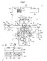
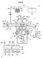
- Fig. 1 is a schematic configuration diagram of major parts of an engine system S (such as a vehicle) to which the present invention is applied.
- This engine system S is provided with an engine 1, and a control device 2 serving as one embodiment of the present invention.
- a side sectional view of the engine 1 by plane orthogonal to the cylinder arranging direction is shown in Fig. 1 .
- the engine 1 is formed so that a mechanical compression ratio is variable within a predetermined range.
- the engine 1 is formed so that the mechanical compression ratio, an actual compression ratio, and an expansion ratio can be substantially independently set and changed.
- the engine 1 is provided with a cylinder block 11, a cylinder head 12, a crankcase 13, and a variable compression ratio mechanism 14.
- An intake passage 15 and an exhaust passage 16 are connected to the engine 1.
- a plurality of cylinder bores 111 is arranged in a row along the cylinder arranging direction in the cylinder block 11.
- a piston 112 is housed inside each of the cylinder bores 111 reciprocably along an axis of the cylinder bore 111 (hereinafter, this axis is referred to as the "cylinder axis CCA").
- the cylinder head 12 is jointed to an upper end of the cylinder block 11, that is, an end of the cylinder block 11 on the top dead center side of the piston 112.
- the cylinder head 12 is fixed to the cylinder block 11 by bolts or the like (not shown).
- a plurality of concave portions is provided at positions corresponding to upper ends of the cylinder bores 111 in a lower end of the cylinder head 12.
- a combustion chamber CC is formed by a space inside the cylinder bore 111 on the upper side of a top surface of the piston 112 (on the side of the cylinder head 12), and a space inside (below) the above concave portion.
- An intake port 121 and an exhaust port 122 are formed in the cylinder head 12 so as to communicate with the combustion chamber CC.
- the cylinder head 12 is provided with an intake valve 123, an exhaust valve 124, a variable intake valve timing device 125, and a variable exhaust valve timing device 126.
- the intake valve 123 is a valve for controlling a communication state between the intake port 121 and the combustion chamber CC.
- the exhaust valve 124 is a valve for controlling a communication state between the exhaust port 122 and the combustion chamber CC.
- the variable intake valve timing device 125 and the variable exhaust valve timing device 126 are formed so as to change the actual compression ratio and the expansion ratio by changing opening and closing timing of the intake valve 123 and the exhaust valve 124. Since specific configurations of the variable intake valve timing device 125 and the variable exhaust valve timing device 126 are already known, more detailed description will be omitted in the present specification.
- the cylinder head 12 is also provided with an injector 127.
- the injector 127 is formed so as to jet fuel to be supplied into the combustion chamber CC into the intake port 121.
- a crankshaft 131 is arranged in parallel to the cylinder arranging direction and rotatably supported in the crankcase 13.
- the crankshaft 131 is coupled to the piston 112 via a connecting rod 132 so as to be rotated and driven based on reciprocating movement of the piston 112 along the cylinder axis CCA.
- variable compression ratio mechanism 14 is formed so as to change the mechanical compression ratio within the above range by relatively moving a joint body of the cylinder block 11 and the cylinder head 12 relative to the crankcase 13 along the cylinder axis CCA.
- This variable compression ratio mechanism 14 is provided with the same configuration as a variable compression ratio mechanism described in Japanese Patent Application Publication No. 2003-206771 or the like. Therefore, in the present specification, detailed description of this mechanism will be omitted, and only an outline thereof will be described below.
- the variable compression ratio mechanism 14 is provided with a coupling mechanism 141, and a drive mechanism 142.
- the coupling mechanism 141 is formed so as to couple the cylinder block 11 and the crankcase 13 movably relative to each other along the cylinder axis CCA.
- the drive mechanism 142 is provided with a motor, a gear mechanism, and the like. This drive mechanism 142 is formed so as to move the cylinder block 11 and the crankcase 13 relative to each other along the cylinder axis CCA.
- the intake passage 15 including an intake manifold, a surge tank, and the like is connected to the intake port 121.
- a throttle valve 151 is placed in the intake passage 15.
- the throttle valve 151 is formed so as to be rotated and driven by a throttle valve actuator 152 formed by a DC motor.
- a fuel tank 153 is connected to the injector 127 via a fuel supply path (not shown).
- a vapor discharge port 153a for discharging "vaporized fuel” (hereinafter, called as the "vapor") is provided in an upper end of the fuel tank 153. The vapor discharged from the fuel tank 153 via the vapor discharge port 153a is absorbed by a canister 154.
- the canister 154 is a known charcoal canister formed so as to absorb a predetermined amount of vapor.
- the canister 154 is provided with a tank port 154a, and a purge port 154b.
- the tank port 154a is connected to the vapor discharge port 153a of the fuel tank 153 via a vapor collecting pipe 155.
- the purge port 154b is connected to a position of the intake passage 15 between the throttle valve 151 and the injector 127 via a purge flow passage 156.
- a purge control valve 157 serving as an electromagnetic open and close valve is placed in the purge flow passage 156.
- the exhaust passage 16 including an exhaust manifold is connected to the exhaust port 122.
- the exhaust passage 16 is a passage of an exhaust gas discharged from the combustion chamber CC via the exhaust port 122.
- An upstream catalyst converter 161 and a downstream catalyst converter 162 are placed in the exhaust passage 16.
- the upstream catalyst converter 161 and the downstream catalyst converter 162 are provided with ternary catalysts having an oxygen absorption function inside thereof, and formed so as to purify HC, CO, and NOx in the exhaust gas.
- the control device 2 is formed so as to control operation of the engine 1 provided with the above configuration, determine (diagnose) states of the parts of the engine system S, and appropriately display determination (diagnosis) results to a driver.
- diagnosis states of the parts of the engine system S
- display determination diagnosis
- the control device 2 is provided with an ECU (electronic control unit) 200.
- the ECU 200 is provided with a CPU 201, a ROM 202, a RAM 203, a backup RAM 204, an interface 205, and a bus 206.
- the CPU 201, the ROM 202, the RAM 203, the backup RAM 204, and the interface 205 are connected to each other by the bus 206.
- Routines to be executed by the CPU 201, tables (look-up tables, maps), parameters, and the like are preliminarily stored in the ROM 202.
- the RAM 203 is formed so as to temporarily store data according to need when the CPU 201 executes the routines.
- the backup RAM 204 is formed so as to store the data when the CPU 201 executes the routines in a power activation state, and to maintain this stored data even after power shut-down.
- the interface 205 is electrically connected to various sensors described below, and formed so as to transmit signals from these sensors to the CPU 201.
- the interface 205 is electrically connected to operating units such as the variable intake valve timing device 125, the variable exhaust valve timing device 126, the injector 127, and the drive mechanism 142, and formed so as to transmit operation signals for operating these operating units from the CPU 201 to these operating units.
- the ECU 200 is formed so as to receive the signals from the various sensors via the interface 205, and send the above operation signals toward the operating units in accordance with calculation results of the CPU 201 based on the signals.
- the engine system S is provided with the various sensors such as a cooling water temperature sensor 211, a crank position sensor 212, an intake cam position sensor 213a, an exhaust cam position sensor 213b, an air flow meter 214, a throttle position sensor 215, an upstream air-fuel ratio sensor 216a, a downstream air-fuel ratio sensor 216b, an exhaust temperature sensor 217, a stroke sensor 218, and an accelerator press-down degree sensor 219.
- sensors such as a cooling water temperature sensor 211, a crank position sensor 212, an intake cam position sensor 213a, an exhaust cam position sensor 213b, an air flow meter 214, a throttle position sensor 215, an upstream air-fuel ratio sensor 216a, a downstream air-fuel ratio sensor 216b, an exhaust temperature sensor 217, a stroke sensor 218, and an accelerator press-down degree sensor 219.
- the cooling water temperature sensor 211 is installed in the cylinder block 11. This cooling water temperature sensor 211 is formed so as to output a signal corresponding to a temperature of cooling water (cooling water temperature Tw) in the cylinder block 11.
- the crank position sensor 212 is installed in the crankcase 13. This crank position sensor 212 is formed so as to output a waveform signal having a pulse in accordance with a rotation angle of the crankshaft 131. Specifically, the crank position sensor 212 is formed so as to output a signal having a narrow pulse for every time when the crankshaft 131 is rotated by 10° and having a wide pulse for every time when the crankshaft 131 is rotated by 360°. That is, the crank position sensor 212 is formed so as to output a signal corresponding to the engine rotation number Ne.
- the intake cam position sensor 213a and the exhaust cam position sensor 213b are installed in the cylinder head 12.
- the intake cam position sensor 213a is formed so as to output a waveform signal having a pulse in accordance with a rotation angle of an intake cam shaft (not shown: included in the variable intake valve timing device 125) for reciprocatingly moving the intake valve 123.
- the exhaust cam position sensor 213b is similarly formed so as to output a waveform signal having a pulse in accordance with a rotation angle of an exhaust cam shaft (not shown).
- the air flow meter 214 and the throttle position sensor 215 are installed in the intake passage 15.
- the air flow meter 214 is formed so as to output a signal corresponding to a mass flow rate of the intake air flowing in the intake passage 15 (intake air flow rate Ga).
- the throttle position sensor 215 is formed so as to output a signal corresponding to a rotation phase of the throttle valve 151 (throttle valve aperture TA).
- the upstream air-fuel ratio sensor 216a and the downstream air-fuel ratio sensor 216b are installed in the exhaust passage 16.
- the upstream air-fuel ratio sensor 216a is arranged on the upstream side in the flowing direction of the exhaust gas relative to the upstream catalyst converter 161.
- the downstream air-fuel ratio sensor 216b is arranged between the upstream catalyst converter 161 and the downstream catalyst converter 162, that is, on the downstream side in the flowing direction of the exhaust gas relative to the upstream catalyst converter 161 and on the upstream side relative to the downstream catalyst converter 162.
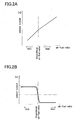
- Fig. 2A is a graph showing an output characteristic of the upstream air-fuel ratio sensor 216a shown in Fig. 1 .
- Fig. 2B is a graph showing an output characteristic of the downstream air-fuel ratio sensor 216b shown in Fig. 1 .
- the upstream air-fuel ratio sensor 216a is an entire-region type air-fuel ratio sensor having a relatively linear output characteristic within a wide air-fuel ratio range. Specifically, this upstream air-fuel ratio sensor 216a is formed by a limiting current type oxygen concentration sensor.
- the downstream air-fuel ratio sensor 216b is an air-fuel ratio sensor having an output characteristic in which an output is substantially fixed on the rich and lean sides of a theoretical air-fuel ratio whereas the output is radically changed around the theoretical air-fuel ratio.
- the downstream air-fuel ratio sensor 216b is formed by a solid electrolyte type zirconium oxygen sensor.
- the exhaust temperature sensor 217 is installed on the upstream side in the flowing direction of the exhaust gas relative to the upstream air-fuel ratio sensor 216a in the exhaust passage 16. This exhaust temperature sensor 217 is formed so as to generate an output in accordance with a temperature of the exhaust gas flowing in the exhaust passage 16.
- the stroke sensor 218 is a linear sensor for generating an output in accordance with a relative position of the cylinder block 11 to the crankcase 13, and is provided so as to be stretched over the cylinder block 11 and the crankcase 13.
- the accelerator press-down degree sensor 219 is formed so as to output a signal corresponding to an operation amount of an accelerator pedal 221 operated by the driver (accelerator operation amount Accp).
- An alarm device 222 provided with an alarm indicating lamp or the like is provided at a position where the alarm device can easily catch eyes of the driver.
- a target air-fuel ratio is set based on the throttle valve aperture TA or the like.
- This target air-fuel ratio is generally set to be the theoretical air-fuel ratio. Meanwhile, at the time of acceleration, etc., the target air-fuel ratio can be set to be a value slightly shifted from the theoretical air-fuel ratio to the rich or lean side, according to need.
- failure diagnosis of the upstream air-fuel ratio sensor 216a and the downstream air-fuel ratio sensor 216b is performed once per one trip (from one start of the engine 1 to stop thereof).
- the target air-fuel ratio is controlled so that it changes in a rectangular waveform between a value shifted from the theoretical air-fuel ratio to the rich side and a value shifted from the theoretical air-fuel ratio to the lean side (so-called air-fuel ratio active control).
- the above air-fuel ratio active control is also performed.
- a basic value of a fuel amount jetted from the injector 127 (basic fuel jet amount) is acquired.
- the basic fuel jet amount is feedback corrected based on outputs from the upstream air-fuel ratio sensor 216a and the downstream air-fuel ratio sensor 216b, so that an actual fuel jet amount from the injector 127 (command fuel jet amount) is acquired.
- air-fuel ratio learning for acquiring the learning correction coefficient at the time of the above open-loop control is performed.
- the OBD of an intake and exhaust system such as the upstream catalyst converter 161, the upstream air-fuel ratio sensor 216a, the downstream air-fuel ratio sensor 216b, and a canister purge system (such as the purge flow passage 156 or the purge control valve 157) is performed by the ECU 200 (CPU 201).
- the catalyst OBD is performed as follows.
- the air-fuel ratio of the fuel-mixing air is forcibly changed into a rectangular waveform.
- the air-fuel ratio of the fuel-mixing air is set to be a predetermined lean air-fuel ratio for a predetermined time.
- oxygen is absorbed by the ternary catalyst of the upstream catalyst converter 161 up to a limit of an absorbing ability.
- the air-fuel ratio of the fuel-mixing air is forcibly changed to a predetermined rich air-fuel ratio.
- the air-fuel ratio detected by the downstream air-fuel ratio sensor 216b is changed to the rich ratio after maintained to be the theoretical air-fuel ratio for a fixed time ⁇ t.
- a maximum oxygen absorption amount in the ternary catalyst of the upstream catalyst converter 161 is determined based on a difference ⁇ (A/F) between the theoretical air-fuel ratio and the rich air-fuel ratio, the time ⁇ t, and an intake air amount of this time. By the acquired value of the maximum oxygen absorption amount, deterioration of the upstream catalyst converter 161 is determined.
- the sensor OBD is performed as follows.
- the air-fuel ratio of the fuel-mixing air is forcibly changed into a rectangular waveform.
- presence of failure of the upstream air-fuel ratio sensor 216a or the downstream air-fuel ratio sensor 216b is determined based on whether or not output waveforms rightly following the air-fuel ratio change are generated.
- trouble determination of the canister purge system is performed based on an output change in the upstream air-fuel ratio sensor 216a when opening and closing of the purge control valve 157 is controlled and purge is controlled to be turned on/off.
- the mechanical compression ratio, the actual compression ratio, and the expansion ratio are controlled based on the operation state of the engine 1 such as a warming-up state and a load state.
- the actual compression ratio is a value determined from actual stroke volume from actual start of a compression operation to arrival of the piston 112 to the top dead center, and clearance volume (volume of the combustion chamber CC with the piston 112 at the top dead center).
- the clearance volume is determined in accordance with a setting state of the mechanical compression ratio.
- the expansion ratio is a ratio of volume at the end of expansion in an expansion stroke and the clearance volume.
- the clearance volume is determined in according with the setting state of the mechanical compression ratio.
- the expansion ratio is variable according to the opening timing of the exhaust valve 124. For example, when the opening timing of the exhaust valve 124 is advanced in order to warm up the upstream catalyst converter 161 at an early stage, so that the temperature of the exhaust gas may be increased. When the opening timing of the exhaust valve 124 is delayed as much as possible, engine thermal efficiency can be enhanced.
- the mechanical compression ratio is set to be high and the opening timing of the exhaust valve 124 is delayed as much as possible, so that the expansion ratio is set to be high (such as about 26) and the engine thermal efficiency is enhanced, and on the other hand, the closing timing of the intake valve 123 is delayed and the actual compression ratio is set to be low
- the mechanical compression ratio and the expansion ratio are set to be high, whereas the closing timing of the intake valve 123 is delayed.
- the actual compression ratio is set to be substantially fixed within a range of a low load or high load of the engine.
- variable compression ratio mechanism 14 the variable intake valve timing device 125, and the variable exhaust valve timing device 126 are controlled so that the mechanical compression ratio and the expansion ratio in the specific OBD are (substantially) fixedly maintained.
- execution of the specific OBD is permitted.
- control system of the compression ratio and the expansion ratio includes the variable compression ratio mechanism 14, the variable intake valve timing device 125, the variable exhaust valve timing device 126, the intake cam position sensor 213a, the exhaust cam position sensor 213b, and the stroke sensor 218.
- this is called as the “compression ratio control system”.
- compression ratio control system can also be called as the “expansion ratio control system”.
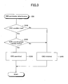
- Fig. 3 is a flowchart showing the first specific example of a determination routine for determining whether or not one OBD is permitted.
- the CPU 201 executes an OBD condition determination routine 300 shown in Fig. 3 at each predetermined timing.
- Step 310 it is determined whether or not an execution condition of one specific OBD (such as a catalyst OBD condition) is met.
- the catalyst OBD condition is that after warming up the engine 1 (cooling water temperature Tw ⁇ Tw0), a change amount of the throttle valve aperture TA per unit time is not more than a predetermined amount, vehicle speed is not less than predetermined speed, and the intake air flow rate is not more than a predetermined rate (intake air flow rate to the extent that so-called "blow-by" is not generated in the upstream catalyst converter 161).
- Step 320 it is determined whether or not the compression ratio control system normally works. Normality determination of this compression ratio control system is performed as follows.
- a catalyst temperature does not quickly follow changes in the actual compression ratio and the expansion ratio. Because of this, merely poor responsiveness of the variable compression ratio mechanism 14 and the stroke sensor 218 does not cause degradation in precision of the catalyst OBD. Therefore, in the case where execution of the OBD condition determination routine 300 of this time relates to condition determination of the catalyst OBD, even when the above (1) is met but (2) and (3) are not met, it is not determined that the failure is generated in the compression ratio control system (Yes in Step 320).
- the execution of the OBD condition determination routine 300 of this time relates to the sensor OBD or the canister purge system OBD, when the above (1) or (4) is met, it is determined that the failure is generated in the compression ratio control system (No in Step 320).
- Step 320 In the case where it is determined that the compression ratio control system normally works (Yes in Step 320), the processing advances to Step 330, the OBD is permitted, and the present routine is once finished. On the other hand, in the case where it is determined that the failure is generated in the compression ratio control system (No in Step 320), the processing advances to Step 340, the OBD is inhibited, and the present routine is once finished.
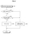
- Fig. 4 is a flowchart showing the second specific example of the determination routine for determining whether or not one OBD is permitted.
- the CPU 201 executes an OBD condition determination routine 400 shown in Fig. 4 at each predetermined timing.
- Step 410 it is determined whether or not an execution condition of one specific OBD is met as well as the above Step 310.
- the processing advances to Step 420, and it is determined whether or not the compression ratio control system normally works.
- Step 420 In the case where it is determined that the compression ratio control system normally works (Yes in Step 420), the processing advances to Step 430, the OBD is permitted, and the present routine is once finished. On the other hand, in the case where it is determined that the failure is generated in the compression ratio control system (No in Step 420), the processing advances to Step 440. In this Step 440, an OBD condition determination sub-routine 500 shown in Fig. 5 is executed.
- Step 510 a trouble (failure) cause of the compression ratio control system is identified.
- This cause identification is performed as (1) to (4) in the above first specific example.
- the processing advances to Step 520, and it is determined whether or not the sensors such as the compression ratio control system sensors (such as the stroke sensor 218) and the exhaust temperature sensor 217 normally work.
- the actual compression ratio or the expansion ratio can be identified, and the actual compression ratio or the expansion ratio comply with the OBD condition (Yes in Step 410).
- the OBD using an estimated temperature of the catalyst (such as the catalyst OBD and the sensor OBD)
- the processing advances to Step 530, the OBD is permitted, and the routines 500 and 400 are once finished.
- Step 520 Even in the case where some failure is found in the sensors (No in Step 520) but the parameters (such as the temperature of the exhaust gas) required for the OBD can be identified (acquired), there is no problem in executing the OBD. Thus, in the case where determination in Step 520 is "No", the processing advances to Step 540, and it is determined whether or not such parameters can be identified (acquired). For example, in the OBD using the temperature of the exhaust gas or the estimated temperature of the catalyst, in the case where at least the exhaust temperature sensor 217 normally works, it is determined that the parameters can be identified (Yes in Step 540). It should be noted that normality determination of this exhaust temperature sensor 217 can be performed based on history or the like of the sensor outputs from the start of the engine 1, for example.
- Step 540 In the case where it is determined that the parameters can be identified (Yes in Step 540), the processing advances to Step 530, the OBD is permitted, and the routines 500 and 400 are once finished. On the other hand, in the case where it is determined that the parameters cannot be identified (No in Step 540), the processing advances to Step 550, the OBD is inhibited, and the routines 500 and 400 are once finished.
- a compression ratio acquiring unit (expansion ratio acquiring unit) of the present invention is realized by the ECU 200 (CPU 201) and the stroke sensor 218.
- a compression ratio control system failure detecting unit of the present invention is realized by the ECU 200 (CPU 201), the stroke sensor 218, and other sensors.
- a temperature acquiring unit of the present invention is realized by the ECU 200 (CPU 201), the exhaust temperature sensor 217, and other sensors.
- an intake and exhaust system determining unit and an intake and exhaust system determination permitting unit of the present invention are realized by the ECU 200 (CPU 201).
- the above embodiment is to only illustrate specific configuration examples of the present invention that the applicant thinks the best at the time of filing the present application. From the beginning, the present invention is not limited to the above embodiment at all. Therefore, the specific configurations shown in the above embodiment can be variously modified within a range not changing essential parts of the present invention, as a matter of course.
- elements whose operations and functions are expressed among the elements forming the means for solving the problem of the present invention include any structures capable of realizing the operations and the functions in addition to the specific structures disclosed in the above embodiment and the modifications.
Landscapes
- Engineering & Computer Science (AREA)
- Chemical & Material Sciences (AREA)
- Combustion & Propulsion (AREA)
- Mechanical Engineering (AREA)
- General Engineering & Computer Science (AREA)
- Output Control And Ontrol Of Special Type Engine (AREA)
- Combined Controls Of Internal Combustion Engines (AREA)
- Exhaust Gas After Treatment (AREA)
Claims (3)
- Maschinensystemsteuervorrichtung zur Anwendung auf ein Maschinensystem, das mit einer Maschine (1) mit einem variablen Kompressionsverhältnismechanismus (14) versehen ist, der in der Lage ist, ein Kompressionsverhältnis zu ändern, welche Folgendes aufweist:eine Kompressionsverhältniserlangungseinheit (200, 218), die gestaltet ist, um einen durch den variablen Kompressionsverhältnismechanismus (14) eingestellten Zustand des Kompressionsverhältnisses zu erlangen;eine Kompressionsverhältnissteuersystemdefekterfassungseinheit (200, 218), die gestaltet ist, um eine Erzeugung eines Defekts in einem Kompressionsverhältnissteuersystem (14, 125, 126, 213a, 213b, 218) einschließlich des variablen Kompressionsverhältnismechanismus (14) und der Kompressionsverhältniserlangungseinheit (200, 218) zu erfassen; undeine Einlass- und Auslasssystembestimmungseinheit (200), die gestaltet ist, um einen Zustand eines Bauteils, das in einem Einlass- und Auslasssystem der Maschine (1) platziert ist, zu bestimmen;
gekennzeichnet durcheine Einlass- und Auslasssystembestimmungsgenehmigungseinheit (200), die gestaltet ist, um eine Bestimmung durch die Einlass- und Auslasssystembestimmungseinheit zu genehmigen, wobeidie Einlass- und Auslasssystembestimmungsgenehmigungseinheit gestaltet ist, um die Bestimmung durch die Einlass- und Auslasssystembestimmungseinheit in dem Fall zu verhindern, in dem die Kompressionsverhältnissteuersystemdefekterfassungseinheit (200, 218) die Erzeugung des Defekts erfasst, unddie Einlass- und Auslasssystembestimmungsgenehmigungseinheit gestaltet ist, um die Bestimmung durch die Einlass- und Auslasssystembestimmungseinheit in dem Fall zu genehmigen, in dem die Kompressionsverhältnissteuersystemdefekterfassungseinheit (200, 218) die Erzeugung des Defekts erfasst, jedoch der Einstellzustand des Kompressionsverhältnisses erlangbar ist. - Maschinensystemsteuervorrichtung nach Anspruch 1,
wobei die Einlass- und Auslasssystembestimmungseinheit gestaltet ist, um den Zustand des Bauteils zu erfassen, das in einem Durchgang (16) eines Abgases platziert ist, das von der Maschine (1) abgegeben wird. - Maschinensystemsteuervorrichtung nach Anspruch 1 oder Anspruch 2, ferner mit:einer Temperaturerlangungseinheit (200, 217), die gestaltet ist, um eine Temperatur des Abgases, das von der Maschine (1) abgegeben wird, oder des Bauteils zu erlangen, das in dem Durchgang (16) des Abgases platziert ist, wobeidie Einlass- und Auslasssystembestimmungsgenehmigungseinheit gestaltet ist, um die Bestimmung durch die Einlass- und Auslasssystembestimmungseinheit in dem Fall zu genehmigen, in dem die Kompressionsverhältnissteuersystemdefekterfassungseinheit (200, 218) die Erzeugung des Defekts erfasst, aber die Temperatur durch die Temperaturerlangungseinheit (200, 217) erlangbar ist.
Applications Claiming Priority (1)
| Application Number | Priority Date | Filing Date | Title |
|---|---|---|---|
| PCT/JP2008/072459 WO2010064329A1 (ja) | 2008-12-03 | 2008-12-03 | エンジンシステム制御装置 |
Publications (3)
| Publication Number | Publication Date |
|---|---|
| EP2362082A1 EP2362082A1 (de) | 2011-08-31 |
| EP2362082A4 EP2362082A4 (de) | 2014-03-12 |
| EP2362082B1 true EP2362082B1 (de) | 2015-05-20 |
Family
ID=42232991
Family Applications (1)
| Application Number | Title | Priority Date | Filing Date |
|---|---|---|---|
| EP20080878587 Not-in-force EP2362082B1 (de) | 2008-12-03 | 2008-12-03 | Motorsystemsteuervorrichtung |
Country Status (5)
| Country | Link |
|---|---|
| US (1) | US8818693B2 (de) |
| EP (1) | EP2362082B1 (de) |
| JP (1) | JP5146704B2 (de) |
| CN (1) | CN102239318B (de) |
| WO (1) | WO2010064329A1 (de) |
Families Citing this family (13)
| Publication number | Priority date | Publication date | Assignee | Title |
|---|---|---|---|---|
| JP2011067766A (ja) | 2009-09-25 | 2011-04-07 | Ricoh Co Ltd | 粉体の製造方法及び流動層式粉砕装置 |
| DE102010032434A1 (de) * | 2010-07-28 | 2012-02-02 | Daimler Ag | Verfahren zum Betreiben einer Hubkolbenmaschine |
| DE102010032487A1 (de) * | 2010-07-28 | 2012-02-02 | Daimler Ag | Verfahren zum Betreiben einer Hubkolbenmaschine |
| WO2012137336A1 (ja) * | 2011-04-07 | 2012-10-11 | トヨタ自動車 株式会社 | バルブタイミング可変装置 |
| JP5825663B2 (ja) * | 2011-07-25 | 2015-12-02 | ボッシュ株式会社 | ラムダセンサの極希薄領域応答性診断方法及びコモンレール式燃料噴射制御装置 |
| JP5754369B2 (ja) * | 2011-12-26 | 2015-07-29 | トヨタ自動車株式会社 | 可変圧縮比機構を備える内燃機関 |
| JP5652573B2 (ja) * | 2012-05-17 | 2015-01-14 | 日産自動車株式会社 | 内燃機関の制御装置及び制御方法 |
| US9051875B2 (en) * | 2012-10-30 | 2015-06-09 | Scott BLACKSTOCK | Variable compression ratio engine |
| MX341046B (es) * | 2013-02-18 | 2016-08-05 | Nissan Motor | Dispositivo de control y metodo de control para motor de combustion interna. |
| JP6287810B2 (ja) * | 2014-12-19 | 2018-03-07 | トヨタ自動車株式会社 | 空燃比センサの異常診断装置 |
| MX2020001705A (es) * | 2017-08-31 | 2020-07-14 | Nissan Motor | Metodo de control y dispositivo de control para motor de combustion interna. |
| JP7132797B2 (ja) * | 2018-08-31 | 2022-09-07 | 三菱重工エンジン&ターボチャージャ株式会社 | Dpf再生制御装置及びdpf再生制御方法 |
| CN114060150B (zh) * | 2020-08-06 | 2023-01-20 | 上海汽车集团股份有限公司 | 汽车发动机压缩比监测系统和汽车 |
Family Cites Families (49)
| Publication number | Priority date | Publication date | Assignee | Title |
|---|---|---|---|---|
| JPH02163429A (ja) | 1988-12-15 | 1990-06-22 | Mazda Motor Corp | 過給機付エンジンの可変圧縮比制御装置 |
| JP2943433B2 (ja) | 1990-08-24 | 1999-08-30 | 株式会社デンソー | 触媒の浄化率検出装置 |
| JP2812023B2 (ja) | 1991-11-12 | 1998-10-15 | トヨタ自動車株式会社 | 触媒劣化度検出装置 |
| JPH06159153A (ja) * | 1992-11-27 | 1994-06-07 | Honda Motor Co Ltd | 排気還流系の異常検出装置 |
| JP3239698B2 (ja) | 1995-07-25 | 2001-12-17 | トヨタ自動車株式会社 | 内燃機関の触媒劣化判定装置 |
| JP3436166B2 (ja) * | 1999-01-21 | 2003-08-11 | 株式会社デンソー | 燃料レベル検出器の異常診断装置 |
| JP4385423B2 (ja) | 1999-02-04 | 2009-12-16 | トヨタ自動車株式会社 | 排気温度測定装置 |
| JP4035963B2 (ja) | 2001-03-27 | 2008-01-23 | 日産自動車株式会社 | 内燃機関の制御装置 |
| JP2003129906A (ja) * | 2001-10-26 | 2003-05-08 | Toyota Motor Corp | 排気還流装置の異常診断装置 |
| US6612288B2 (en) | 2001-11-06 | 2003-09-02 | Ford Global Technologies, Llc | Diagnostic method for variable compression ratio engine |
| JP4165074B2 (ja) | 2002-01-17 | 2008-10-15 | トヨタ自動車株式会社 | 内燃機関 |
| JP2003254135A (ja) | 2002-03-06 | 2003-09-10 | Toyota Motor Corp | 空燃比センサの異常診断装置 |
| US7043349B2 (en) | 2002-04-25 | 2006-05-09 | Ford Global Technologies, Llc | Method and system for inferring exhaust temperature of a variable compression ratio engine |
| JP3963130B2 (ja) | 2002-06-27 | 2007-08-22 | トヨタ自動車株式会社 | 触媒劣化判定装置 |
| JP2004156541A (ja) | 2002-11-07 | 2004-06-03 | Nippon Soken Inc | 可変圧縮比機構を有する内燃機関 |
| JP4165194B2 (ja) | 2002-11-22 | 2008-10-15 | トヨタ自動車株式会社 | エンジンの圧縮比変更方法と可変圧縮比エンジン |
| JP4161771B2 (ja) | 2002-11-27 | 2008-10-08 | トヨタ自動車株式会社 | 酸素センサの異常検出装置 |
| JP4341240B2 (ja) | 2002-12-20 | 2009-10-07 | トヨタ自動車株式会社 | 内燃機関の制御装置 |
| JP3945422B2 (ja) | 2003-03-03 | 2007-07-18 | トヨタ自動車株式会社 | 圧縮比変更期間における内燃機関の制御 |
| JP4155069B2 (ja) | 2003-03-17 | 2008-09-24 | トヨタ自動車株式会社 | 圧縮比を変更可能な内燃機関における運転開始時の制御 |
| JP2004308510A (ja) | 2003-04-04 | 2004-11-04 | Toyota Motor Corp | 圧縮比変更機構の故障を検知して制御を行う内燃機関 |
| JP4161789B2 (ja) * | 2003-04-25 | 2008-10-08 | いすゞ自動車株式会社 | 燃料噴射制御装置 |
| JP2005002854A (ja) | 2003-06-11 | 2005-01-06 | Nissan Motor Co Ltd | エンジンの排気ガス浄化装置 |
| JP4341456B2 (ja) | 2003-08-06 | 2009-10-07 | トヨタ自動車株式会社 | 内燃機関の排気浄化触媒劣化判定方法及び劣化判定装置 |
| JP4200860B2 (ja) | 2003-08-28 | 2008-12-24 | 日産自動車株式会社 | 可変圧縮比機構付き内燃機関 |
| CA2441686C (en) * | 2003-09-23 | 2004-12-21 | Westport Research Inc. | Method for controlling combustion in an internal combustion engine and predicting performance and emissions |
| JP4353022B2 (ja) | 2004-07-27 | 2009-10-28 | トヨタ自動車株式会社 | 内燃機関の制御装置 |
| JP4501584B2 (ja) | 2004-08-05 | 2010-07-14 | 日産自動車株式会社 | 内燃機関の圧縮比制御装置 |
| JP4403958B2 (ja) | 2004-12-03 | 2010-01-27 | 日産自動車株式会社 | 内燃機関の制御装置 |
| JP4605642B2 (ja) | 2004-12-14 | 2011-01-05 | 株式会社デンソー | 内燃機関のノック判定装置 |
| JP4221600B2 (ja) | 2004-12-27 | 2009-02-12 | 三菱自動車工業株式会社 | 内燃機関の制御装置 |
| JP4507957B2 (ja) | 2005-04-06 | 2010-07-21 | トヨタ自動車株式会社 | 内燃機関の触媒劣化検出装置 |
| JP4412218B2 (ja) | 2005-04-08 | 2010-02-10 | トヨタ自動車株式会社 | 内燃機関の制御装置及び内燃機関の排気温度推定方法 |
| JP2007016712A (ja) | 2005-07-08 | 2007-01-25 | Toyota Motor Corp | 酸素センサの異常検出装置 |
| JP4483743B2 (ja) | 2005-08-26 | 2010-06-16 | トヨタ自動車株式会社 | 可変圧縮比内燃機関 |
| JP2007064089A (ja) | 2005-08-31 | 2007-03-15 | Toyota Motor Corp | 内燃機関の排気系部品の温度推定装置 |
| JP4604922B2 (ja) | 2005-09-01 | 2011-01-05 | トヨタ自動車株式会社 | 可変圧縮比内燃機関 |
| JP4492523B2 (ja) * | 2005-10-31 | 2010-06-30 | トヨタ自動車株式会社 | 圧縮比とバルブ特性を変更可能な内燃機関 |
| JP2007213820A (ja) | 2006-02-07 | 2007-08-23 | Hitachi Vehicle Energy Ltd | 二次電池 |
| JP4929781B2 (ja) | 2006-03-27 | 2012-05-09 | 日産自動車株式会社 | Dpf再生制御装置及びdpf再生制御方法 |
| JP2007262945A (ja) | 2006-03-28 | 2007-10-11 | Denso Corp | 排出ガスセンサの異常診断装置 |
| JP2007303423A (ja) | 2006-05-12 | 2007-11-22 | Toyota Motor Corp | 火花点火式内燃機関 |
| JP4237202B2 (ja) | 2006-06-06 | 2009-03-11 | 三菱電機株式会社 | 空燃比フィードバック制御装置 |
| JP4259546B2 (ja) | 2006-07-13 | 2009-04-30 | トヨタ自動車株式会社 | 火花点火式内燃機関 |
| JP4716189B2 (ja) | 2006-11-29 | 2011-07-06 | トヨタ自動車株式会社 | 排気ガス切替弁の故障診断装置 |
| JP2008152318A (ja) * | 2006-12-14 | 2008-07-03 | Denso Corp | 制御装置および異常判定装置 |
| JP4631848B2 (ja) | 2006-12-25 | 2011-02-16 | トヨタ自動車株式会社 | 火花点火式内燃機関 |
| JP2007177792A (ja) * | 2007-02-19 | 2007-07-12 | Toyota Motor Corp | 圧縮比変更機構を備えた内燃機関および内燃機関の制御方法 |
| JP2007224927A (ja) * | 2007-06-11 | 2007-09-06 | Toyota Motor Corp | 圧縮比変更機構の故障を検知して制御を行う内燃機関 |
-
2008
- 2008-12-03 EP EP20080878587 patent/EP2362082B1/de not_active Not-in-force
- 2008-12-03 JP JP2010541184A patent/JP5146704B2/ja not_active Expired - Fee Related
- 2008-12-03 WO PCT/JP2008/072459 patent/WO2010064329A1/ja not_active Ceased
- 2008-12-03 US US13/132,451 patent/US8818693B2/en active Active
- 2008-12-03 CN CN200880132216.6A patent/CN102239318B/zh not_active Expired - Fee Related
Also Published As
| Publication number | Publication date |
|---|---|
| CN102239318A (zh) | 2011-11-09 |
| WO2010064329A1 (ja) | 2010-06-10 |
| US8818693B2 (en) | 2014-08-26 |
| EP2362082A1 (de) | 2011-08-31 |
| EP2362082A4 (de) | 2014-03-12 |
| JP5146704B2 (ja) | 2013-02-20 |
| JPWO2010064329A1 (ja) | 2012-05-10 |
| CN102239318B (zh) | 2014-03-26 |
| US20110290217A1 (en) | 2011-12-01 |
Similar Documents
| Publication | Publication Date | Title |
|---|---|---|
| EP2362082B1 (de) | Motorsystemsteuervorrichtung | |
| US8656701B2 (en) | Control device | |
| US8091404B2 (en) | Abnormality diagnosis apparatus for NOx sensor | |
| US8078392B2 (en) | Unburned fuel amount-estimating device in engine and temperature-estimating device of exhaust emission purifier | |
| US7249454B2 (en) | Fuel injection control apparatus and fuel injection control method for internal combustion engine | |
| EP1657415B1 (de) | Selbstdiagnose Vorrichtung eines Verbrennungsmotors | |
| EP2888464B1 (de) | Steuerungsvefahren und steuerungsvorrichtung für eine brennkraftmaschine | |
| US9810132B2 (en) | Catalyst deterioration diagnosis apparatus | |
| US9228522B2 (en) | Supercharger-equipped internal combustion engine | |
| CN103291475B (zh) | 关于启动和维持内燃发动机的亚化学计量运行模式的方法以及实施此种方法的内燃发动机 | |
| CN106121845A (zh) | 一种控制内燃发动机的方法 | |
| JP2006316746A (ja) | 内燃機関の排ガス浄化装置 | |
| US10337437B2 (en) | Abnormality diagnosis device and abnormality diagnosis method for internal combustion engine | |
| JP5013097B2 (ja) | エンジンの制御装置、エンジンの燃料供給系の異常診断方法、コンピュータプログラム、及び記録媒体 | |
| JP2015121182A (ja) | エンジンの制御装置 | |
| JP4747079B2 (ja) | 内燃機関の排ガス浄化装置 | |
| JP2009264150A (ja) | 制御装置 | |
| US12364944B2 (en) | Method for monitoring a regeneration of a particulate filter in the exhaust system of an internal combustion engine | |
| JP2020045818A (ja) | 診断装置 | |
| JP5817996B2 (ja) | 空燃比センサ異常診断装置 |
Legal Events
| Date | Code | Title | Description |
|---|---|---|---|
| PUAI | Public reference made under article 153(3) epc to a published international application that has entered the european phase |
Free format text: ORIGINAL CODE: 0009012 |
|
| 17P | Request for examination filed |
Effective date: 20110614 |
|
| AK | Designated contracting states |
Kind code of ref document: A1 Designated state(s): AT BE BG CH CY CZ DE DK EE ES FI FR GB GR HR HU IE IS IT LI LT LU LV MC MT NL NO PL PT RO SE SI SK TR |
|
| DAX | Request for extension of the european patent (deleted) | ||
| RAP1 | Party data changed (applicant data changed or rights of an application transferred) |
Owner name: TOYOTA JIDOSHA KABUSHIKI KAISHA |
|
| A4 | Supplementary search report drawn up and despatched |
Effective date: 20140212 |
|
| RIC1 | Information provided on ipc code assigned before grant |
Ipc: F02D 41/02 20060101ALI20140206BHEP Ipc: F02D 15/04 20060101AFI20140206BHEP Ipc: F02D 41/22 20060101ALI20140206BHEP Ipc: F02D 43/00 20060101ALI20140206BHEP Ipc: F02D 41/14 20060101ALI20140206BHEP Ipc: F02D 15/00 20060101ALI20140206BHEP |
|
| GRAP | Despatch of communication of intention to grant a patent |
Free format text: ORIGINAL CODE: EPIDOSNIGR1 |
|
| INTG | Intention to grant announced |
Effective date: 20141204 |
|
| RIN1 | Information on inventor provided before grant (corrected) |
Inventor name: KIDOKORO, TORU Inventor name: SAWADA, HIROSHI Inventor name: KIMURA, KOICHI |
|
| GRAS | Grant fee paid |
Free format text: ORIGINAL CODE: EPIDOSNIGR3 |
|
| GRAA | (expected) grant |
Free format text: ORIGINAL CODE: 0009210 |
|
| AK | Designated contracting states |
Kind code of ref document: B1 Designated state(s): AT BE BG CH CY CZ DE DK EE ES FI FR GB GR HR HU IE IS IT LI LT LU LV MC MT NL NO PL PT RO SE SI SK TR |
|
| REG | Reference to a national code |
Ref country code: GB Ref legal event code: FG4D |
|
| REG | Reference to a national code |
Ref country code: CH Ref legal event code: EP |
|
| REG | Reference to a national code |
Ref country code: AT Ref legal event code: REF Ref document number: 727880 Country of ref document: AT Kind code of ref document: T Effective date: 20150615 |
|
| REG | Reference to a national code |
Ref country code: IE Ref legal event code: FG4D |
|
| REG | Reference to a national code |
Ref country code: DE Ref legal event code: R096 Ref document number: 602008038279 Country of ref document: DE |
|
| REG | Reference to a national code |
Ref country code: DE Ref legal event code: R082 Ref document number: 602008038279 Country of ref document: DE Representative=s name: TBK, DE |
|
| REG | Reference to a national code |
Ref country code: DE Ref legal event code: R084 Ref document number: 602008038279 Country of ref document: DE |
|
| REG | Reference to a national code |
Ref country code: AT Ref legal event code: MK05 Ref document number: 727880 Country of ref document: AT Kind code of ref document: T Effective date: 20150520 |
|
| REG | Reference to a national code |
Ref country code: LT Ref legal event code: MG4D |
|
| REG | Reference to a national code |
Ref country code: NL Ref legal event code: MP Effective date: 20150520 |
|
| PG25 | Lapsed in a contracting state [announced via postgrant information from national office to epo] |
Ref country code: ES Free format text: LAPSE BECAUSE OF FAILURE TO SUBMIT A TRANSLATION OF THE DESCRIPTION OR TO PAY THE FEE WITHIN THE PRESCRIBED TIME-LIMIT Effective date: 20150520 Ref country code: LT Free format text: LAPSE BECAUSE OF FAILURE TO SUBMIT A TRANSLATION OF THE DESCRIPTION OR TO PAY THE FEE WITHIN THE PRESCRIBED TIME-LIMIT Effective date: 20150520 Ref country code: HR Free format text: LAPSE BECAUSE OF FAILURE TO SUBMIT A TRANSLATION OF THE DESCRIPTION OR TO PAY THE FEE WITHIN THE PRESCRIBED TIME-LIMIT Effective date: 20150520 Ref country code: NO Free format text: LAPSE BECAUSE OF FAILURE TO SUBMIT A TRANSLATION OF THE DESCRIPTION OR TO PAY THE FEE WITHIN THE PRESCRIBED TIME-LIMIT Effective date: 20150820 Ref country code: PT Free format text: LAPSE BECAUSE OF FAILURE TO SUBMIT A TRANSLATION OF THE DESCRIPTION OR TO PAY THE FEE WITHIN THE PRESCRIBED TIME-LIMIT Effective date: 20150921 Ref country code: FI Free format text: LAPSE BECAUSE OF FAILURE TO SUBMIT A TRANSLATION OF THE DESCRIPTION OR TO PAY THE FEE WITHIN THE PRESCRIBED TIME-LIMIT Effective date: 20150520 |
|
| PG25 | Lapsed in a contracting state [announced via postgrant information from national office to epo] |
Ref country code: GR Free format text: LAPSE BECAUSE OF FAILURE TO SUBMIT A TRANSLATION OF THE DESCRIPTION OR TO PAY THE FEE WITHIN THE PRESCRIBED TIME-LIMIT Effective date: 20150821 Ref country code: LV Free format text: LAPSE BECAUSE OF FAILURE TO SUBMIT A TRANSLATION OF THE DESCRIPTION OR TO PAY THE FEE WITHIN THE PRESCRIBED TIME-LIMIT Effective date: 20150520 Ref country code: IS Free format text: LAPSE BECAUSE OF FAILURE TO SUBMIT A TRANSLATION OF THE DESCRIPTION OR TO PAY THE FEE WITHIN THE PRESCRIBED TIME-LIMIT Effective date: 20150920 Ref country code: AT Free format text: LAPSE BECAUSE OF FAILURE TO SUBMIT A TRANSLATION OF THE DESCRIPTION OR TO PAY THE FEE WITHIN THE PRESCRIBED TIME-LIMIT Effective date: 20150520 Ref country code: BG Free format text: LAPSE BECAUSE OF FAILURE TO SUBMIT A TRANSLATION OF THE DESCRIPTION OR TO PAY THE FEE WITHIN THE PRESCRIBED TIME-LIMIT Effective date: 20150820 |
|
| PG25 | Lapsed in a contracting state [announced via postgrant information from national office to epo] |
Ref country code: DK Free format text: LAPSE BECAUSE OF FAILURE TO SUBMIT A TRANSLATION OF THE DESCRIPTION OR TO PAY THE FEE WITHIN THE PRESCRIBED TIME-LIMIT Effective date: 20150520 Ref country code: EE Free format text: LAPSE BECAUSE OF FAILURE TO SUBMIT A TRANSLATION OF THE DESCRIPTION OR TO PAY THE FEE WITHIN THE PRESCRIBED TIME-LIMIT Effective date: 20150520 |
|
| REG | Reference to a national code |
Ref country code: DE Ref legal event code: R097 Ref document number: 602008038279 Country of ref document: DE |
|
| PG25 | Lapsed in a contracting state [announced via postgrant information from national office to epo] |
Ref country code: PL Free format text: LAPSE BECAUSE OF FAILURE TO SUBMIT A TRANSLATION OF THE DESCRIPTION OR TO PAY THE FEE WITHIN THE PRESCRIBED TIME-LIMIT Effective date: 20150520 Ref country code: SK Free format text: LAPSE BECAUSE OF FAILURE TO SUBMIT A TRANSLATION OF THE DESCRIPTION OR TO PAY THE FEE WITHIN THE PRESCRIBED TIME-LIMIT Effective date: 20150520 Ref country code: RO Free format text: LAPSE BECAUSE OF NON-PAYMENT OF DUE FEES Effective date: 20150520 Ref country code: CZ Free format text: LAPSE BECAUSE OF FAILURE TO SUBMIT A TRANSLATION OF THE DESCRIPTION OR TO PAY THE FEE WITHIN THE PRESCRIBED TIME-LIMIT Effective date: 20150520 |
|
| PLBE | No opposition filed within time limit |
Free format text: ORIGINAL CODE: 0009261 |
|
| STAA | Information on the status of an ep patent application or granted ep patent |
Free format text: STATUS: NO OPPOSITION FILED WITHIN TIME LIMIT |
|
| 26N | No opposition filed |
Effective date: 20160223 |
|
| PG25 | Lapsed in a contracting state [announced via postgrant information from national office to epo] |
Ref country code: IT Free format text: LAPSE BECAUSE OF FAILURE TO SUBMIT A TRANSLATION OF THE DESCRIPTION OR TO PAY THE FEE WITHIN THE PRESCRIBED TIME-LIMIT Effective date: 20150520 |
|
| PG25 | Lapsed in a contracting state [announced via postgrant information from national office to epo] |
Ref country code: BE Free format text: LAPSE BECAUSE OF NON-PAYMENT OF DUE FEES Effective date: 20151231 Ref country code: SI Free format text: LAPSE BECAUSE OF FAILURE TO SUBMIT A TRANSLATION OF THE DESCRIPTION OR TO PAY THE FEE WITHIN THE PRESCRIBED TIME-LIMIT Effective date: 20150520 |
|
| PG25 | Lapsed in a contracting state [announced via postgrant information from national office to epo] |
Ref country code: MC Free format text: LAPSE BECAUSE OF FAILURE TO SUBMIT A TRANSLATION OF THE DESCRIPTION OR TO PAY THE FEE WITHIN THE PRESCRIBED TIME-LIMIT Effective date: 20150520 Ref country code: LU Free format text: LAPSE BECAUSE OF FAILURE TO SUBMIT A TRANSLATION OF THE DESCRIPTION OR TO PAY THE FEE WITHIN THE PRESCRIBED TIME-LIMIT Effective date: 20151203 |
|
| REG | Reference to a national code |
Ref country code: CH Ref legal event code: PL |
|
| GBPC | Gb: european patent ceased through non-payment of renewal fee |
Effective date: 20151203 |
|
| PG25 | Lapsed in a contracting state [announced via postgrant information from national office to epo] |
Ref country code: BE Free format text: LAPSE BECAUSE OF FAILURE TO SUBMIT A TRANSLATION OF THE DESCRIPTION OR TO PAY THE FEE WITHIN THE PRESCRIBED TIME-LIMIT Effective date: 20150520 |
|
| REG | Reference to a national code |
Ref country code: IE Ref legal event code: MM4A |
|
| REG | Reference to a national code |
Ref country code: FR Ref legal event code: ST Effective date: 20160831 |
|
| PG25 | Lapsed in a contracting state [announced via postgrant information from national office to epo] |
Ref country code: IE Free format text: LAPSE BECAUSE OF NON-PAYMENT OF DUE FEES Effective date: 20151203 Ref country code: CH Free format text: LAPSE BECAUSE OF NON-PAYMENT OF DUE FEES Effective date: 20151231 Ref country code: GB Free format text: LAPSE BECAUSE OF NON-PAYMENT OF DUE FEES Effective date: 20151203 Ref country code: LI Free format text: LAPSE BECAUSE OF NON-PAYMENT OF DUE FEES Effective date: 20151231 |
|
| PG25 | Lapsed in a contracting state [announced via postgrant information from national office to epo] |
Ref country code: FR Free format text: LAPSE BECAUSE OF NON-PAYMENT OF DUE FEES Effective date: 20151231 |
|
| PG25 | Lapsed in a contracting state [announced via postgrant information from national office to epo] |
Ref country code: HU Free format text: LAPSE BECAUSE OF FAILURE TO SUBMIT A TRANSLATION OF THE DESCRIPTION OR TO PAY THE FEE WITHIN THE PRESCRIBED TIME-LIMIT; INVALID AB INITIO Effective date: 20081203 |
|
| PG25 | Lapsed in a contracting state [announced via postgrant information from national office to epo] |
Ref country code: SE Free format text: LAPSE BECAUSE OF FAILURE TO SUBMIT A TRANSLATION OF THE DESCRIPTION OR TO PAY THE FEE WITHIN THE PRESCRIBED TIME-LIMIT Effective date: 20150520 Ref country code: NL Free format text: LAPSE BECAUSE OF FAILURE TO SUBMIT A TRANSLATION OF THE DESCRIPTION OR TO PAY THE FEE WITHIN THE PRESCRIBED TIME-LIMIT Effective date: 20150520 Ref country code: CY Free format text: LAPSE BECAUSE OF FAILURE TO SUBMIT A TRANSLATION OF THE DESCRIPTION OR TO PAY THE FEE WITHIN THE PRESCRIBED TIME-LIMIT Effective date: 20150520 |
|
| PG25 | Lapsed in a contracting state [announced via postgrant information from national office to epo] |
Ref country code: MT Free format text: LAPSE BECAUSE OF FAILURE TO SUBMIT A TRANSLATION OF THE DESCRIPTION OR TO PAY THE FEE WITHIN THE PRESCRIBED TIME-LIMIT Effective date: 20150520 Ref country code: TR Free format text: LAPSE BECAUSE OF FAILURE TO SUBMIT A TRANSLATION OF THE DESCRIPTION OR TO PAY THE FEE WITHIN THE PRESCRIBED TIME-LIMIT Effective date: 20150520 |
|
| PGFP | Annual fee paid to national office [announced via postgrant information from national office to epo] |
Ref country code: DE Payment date: 20211102 Year of fee payment: 14 |
|
| REG | Reference to a national code |
Ref country code: DE Ref legal event code: R119 Ref document number: 602008038279 Country of ref document: DE |
|
| PG25 | Lapsed in a contracting state [announced via postgrant information from national office to epo] |
Ref country code: DE Free format text: LAPSE BECAUSE OF NON-PAYMENT OF DUE FEES Effective date: 20230701 |