EP2362107A2 - Rivet de serrage - Google Patents
Rivet de serrage Download PDFInfo
- Publication number
- EP2362107A2 EP2362107A2 EP11152032A EP11152032A EP2362107A2 EP 2362107 A2 EP2362107 A2 EP 2362107A2 EP 11152032 A EP11152032 A EP 11152032A EP 11152032 A EP11152032 A EP 11152032A EP 2362107 A2 EP2362107 A2 EP 2362107A2
- Authority
- EP
- European Patent Office
- Prior art keywords
- support plate
- spring arms
- tensioning
- rivet
- threaded ring
- Prior art date
- Legal status (The legal status is an assumption and is not a legal conclusion. Google has not performed a legal analysis and makes no representation as to the accuracy of the status listed.)
- Granted
Links
Images



Classifications
-
- F—MECHANICAL ENGINEERING; LIGHTING; HEATING; WEAPONS; BLASTING
- F16—ENGINEERING ELEMENTS AND UNITS; GENERAL MEASURES FOR PRODUCING AND MAINTAINING EFFECTIVE FUNCTIONING OF MACHINES OR INSTALLATIONS; THERMAL INSULATION IN GENERAL
- F16B—DEVICES FOR FASTENING OR SECURING CONSTRUCTIONAL ELEMENTS OR MACHINE PARTS TOGETHER, e.g. NAILS, BOLTS, CIRCLIPS, CLAMPS, CLIPS OR WEDGES; JOINTS OR JOINTING
- F16B19/00—Bolts without screw-thread; Pins, including deformable elements; Rivets
- F16B19/04—Rivets; Spigots or the like fastened by riveting
- F16B19/08—Hollow rivets; Multi-part rivets
- F16B19/10—Hollow rivets; Multi-part rivets fastened by expanding mechanically
- F16B19/1027—Multi-part rivets
- F16B19/1036—Blind rivets
- F16B19/1081—Blind rivets fastened by a drive-pin
-
- F—MECHANICAL ENGINEERING; LIGHTING; HEATING; WEAPONS; BLASTING
- F16—ENGINEERING ELEMENTS AND UNITS; GENERAL MEASURES FOR PRODUCING AND MAINTAINING EFFECTIVE FUNCTIONING OF MACHINES OR INSTALLATIONS; THERMAL INSULATION IN GENERAL
- F16B—DEVICES FOR FASTENING OR SECURING CONSTRUCTIONAL ELEMENTS OR MACHINE PARTS TOGETHER, e.g. NAILS, BOLTS, CIRCLIPS, CLAMPS, CLIPS OR WEDGES; JOINTS OR JOINTING
- F16B5/00—Joining sheets or plates, e.g. panels, to one another or to strips or bars parallel to them
- F16B5/06—Joining sheets or plates, e.g. panels, to one another or to strips or bars parallel to them by means of clamps or clips
- F16B5/0607—Joining sheets or plates, e.g. panels, to one another or to strips or bars parallel to them by means of clamps or clips joining sheets or plates to each other
- F16B5/0621—Joining sheets or plates, e.g. panels, to one another or to strips or bars parallel to them by means of clamps or clips joining sheets or plates to each other in parallel relationship
- F16B5/0642—Joining sheets or plates, e.g. panels, to one another or to strips or bars parallel to them by means of clamps or clips joining sheets or plates to each other in parallel relationship the plates being arranged one on top of the other and in full close contact with each other
Definitions
- the invention relates to a Spannniet according to the preamble of claim 1.
- tension rivet is out DE 10 2005 062 242 B3 known.
- the previously known tensioning rivet has an insert body which has a support plate and a base connected to the support plate.
- the foot rest is formed with at least two spring arms each having a rear grip nose.
- a push-in pin is present, which can be inserted radially inwardly into the footrest for blocking the spring arms against compression.
- the invention has for its object to provide a Spannniet of the type mentioned, which is in a pre-assembly captively secured to an assembly of an attachment and from a support member.
- the tension rivet can be taken Screw a pre-assembly into an assembly of an attachment and a support member and secure against a sole provision of Schugriffnasen higher pull-out force in the pre-assembly against unintentional loosening.
- the spring arms After inserting the insertion pin into the foot rest, the spring arms are then blocked against compression in a radially inward direction, so that they now essentially exercise the blocking function alone. After pulling out of the insertion pin from the foot with releasing the spring arms is fixed depending on the configuration of the threaded ring in the support plate facing the area of the clamping rivet releasably or permanently.
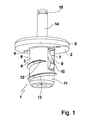
- Fig. 1 shows a perspective view of an embodiment of a detachable tensioning rivet according to the invention.
- the tensioning rivet according to the invention Fig. 1 has an insert body 1, which has a disc-like support plate 2 and an integrally formed on the support plate 2, extending in a longitudinal direction of the Spannniets hollow cylinder-likeêtschaft 3.
- the support plate 2 is formed with at least one, but preferably with at least two horrinskyinskyinskyinskyinskyinskyinskyinskyinskyinskyinskyinskyinskyinskyinskyinskyinskyinskyinskyinskyinskyinskyinskyinskyinskyinskyinskyinskyinskyinskyinskyinskyinskyinskyinskyinskyinskyinskyinskyinskyinskyinskyinskyinskyinskyinskyinskyinskyinskyinskyinskyinskyinskyinskyinskyinskyinskyinskyinskyinskyinskyinskyinskyinskyinskyinskyinskyinskyinskyinskyinskyinskyinskyinskyinskyinskyinskyinskyinskyinskyinskyinskyinskyinskyinskyinskyinskyinskyinskyinskyinskyinskyinskyinskyinskyinskyinskyinskyinskyinskyinskyinskyinskyinskyinskyinskyinskyinskyinskyinskyinskyinskyinskyinskyinskyinskyinskyin
- Theticianschaft 3 in the embodiment according to Fig. 1 has two ArmausEnglishept 6, 7, in each of which a spring arm 8, 9 is arranged.
- Each spring arm 8, 9 is with one end, for example, as in Fig. 1 shown connected to the insert body 1 in the region of the support plate 2.
- the spring arms 8, 9 are respectively connected to the support plate 2 opposite end of the Armausappelisme 6, 7.
- Each spring arm 8, 9 is formed with a Weg Bachnase 10, which protrude radially outwardly beyond the solicitschaft 3.
- the spring arms 8, 9 are so sufficiently flexible and free that when exerting a predetermined mounting force, the spring arms 8, 9 can deflect radially inward until the rear handle lugs 10 are flush with the circumference of the foot shaft 3.
- the foot shaft 3 is formed with a support plate 2 facing away from, circumferentially closed foot end 11. From the foot end 11 extends spirally in the direction of the support plate 2, a threaded ring 12, which has a substantially triangular cross-section due to two inclined mutually aligned side surfaces.
- a threaded ring 12 which has a substantially triangular cross-section due to two inclined mutually aligned side surfaces.
- the threaded ring 12 over its entire length, which corresponds to about 1.5 times the circumference of the foot shaft 3 in this embodiment, a continuous, pointing in the direction of the support plate 2 slope and runs in one between the Schugriffnasen 10 and the support plate 2 lying portion of theticianschaftes 3 with a retracted in the radial direction up to the outer surface of theticianschaftes 3, expiring end portion 13 from.
- the tensioning rivet according to the invention Fig. 1 is further equipped with a cylindrical massive insertion pin 14 which is slidably held in the modiser 3 and at its end facing away from the demandingschaft 3 with a circumferentially extending pull-out notch 15 is formed.
- Fig. 2 shows a side view of the embodiment of a tensioning rivet according to the invention Fig. 1 in a final assembly position when attaching an attachment 16 to a support member 17, in which the insertion pin 14 is substantially completely inserted into the base 3 except for the protruding longitudinally over the support plate 2 Auszugskerbe 15.
- the rear grip lugs 10 engage behind the carrier part 17 on its side remote from the attachment 16, while the support plate 2 rests on the side of the attachment 16 facing away from the carrier part 17.
- the threaded ring 12 secures the insert body 1 to the arrangement of attachment 16 and support member 17 in addition to the rear grip lugs 10, wherein by forming the threaded ring 12 with a continuous Increase upon engagement of the support plate 2 facing end portion 13 of the threaded ring 12 with a correspondingly dimensioned notch in the support member 17 of the invention Spannniet 11 by unscrewing again from the support member 17 is removable once the insertion pin 14 has been pulled out of thetician 3 again.
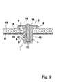
- Fig. 3 shows a sectional view of the embodiment of a tensioning rivet according to the invention in the final assembly position according to Fig. 3 , Out Fig. 3
- the tensioning rivet according to the invention is secured in the final assembly position against very high pull-out forces on the arrangement of carrier part 17 and attachment part 16.
- the threaded ring 12 also serves, for example, as an emergency securing means engaging behind the carrier part 17 if the blocking of the spring arms 8, 9 is canceled.
- the insert body 1 is arranged in a relation to the largest diameter of theticianschaftes 3 with relaxed spring arms 8, 9 larger sized fürsteckaus principleung 18 of the attachment 16, while a introduced in the support member 17 receiving recess 19 is dimensioned so small that the threaded ring 12, the support member 17th engages behind on its side facing away from the attachment 16.
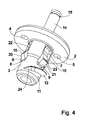
- Fig. 4 shows in a perspective view of another embodiment of a tensioning rivet according to the invention, wherein in the embodiment according to Fig. 1 and in the embodiment according to Fig. 4 Corresponding elements provided with the same reference numerals and are further explained in part in detail.
- the embodiment according to Fig. 4 has a total of four spring arms 8, 9, 20, 21, which are arranged in associated ArmausEnglishept 6, 7, 22, 23.
- the spring arms 8, 9, 20, 21 are arranged in pairs diametrically opposite, so that they have in the circumferential direction an angular distance of 90 degrees from each other.
- the Schugriffnasen 10 of diametrically opposite spring arms 8, 9; 20, 21 are opposite the rear grip lugs 10 of the other, intermediate spring arm pair 20, 21; 8, 9 offset in the longitudinal direction of the foot shaft 3 to each other, so that the tension rivet according to Fig. 4 by a relatively large thickness tolerance with respect to the thickness of an in Fig. 4 Anbauerss not shown and a in Fig. 4 likewise not shown carrier part. Furthermore, results from a total of four spring arms 8, 9, 20, 21, a relatively high pull-out force.
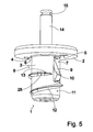
- Fig. 5 shows in a perspective view of another embodiment of an insoluble tension rivet according to the invention with two spring arms 8, 9, wherein in the embodiment according to Fig. 1 , in the embodiment according to Fig. 4 and in the embodiment according to Fig. 5 Corresponding elements provided with the same reference numerals and are further explained in part in detail.
- the threaded ring 12 runs at its end facing the support plate 2 end in a the end portion 13 upstream outlet portion 25 ste Trentslos, that is in a direction perpendicular to the longitudinal direction of theticianschaftes 3, from.
- the end portion 13 is also arranged stepless.
- Both the end portion 13 and the outlet portion 25 lie in a common, at right angles to the longitudinal direction of the contemplatschaftes 3 aligned plane.
- this clamping rivet is inextricably connected by screwing with a support member 17, since a required for unscrewing notch for this would have to be sized so large that a reliable anchoring of the tension rivet would no longer be guaranteed.
- Fig. 6 shows a side view of the embodiment of a tensioning rivet according to the invention Fig. 6 in a final assembly position according to Fig. 2 , Out Fig. 6 It can be seen that the stepless end portion 13 and the stepless outlet portion 25 engage behind the support member 17 on its side facing away from the attachment 16 and thereby even with a pulled out of theticianschaft 3 insert pin 14 the tension rivet against relatively high pull-out forces resistant to the support member 17 secures.
- Fig. 7 shows in a sectional view of the embodiment according to Fig. 5 in the final assembly position according to Fig. 6 , Out Fig. 7 It can be seen that the threaded ring 12 terminates in a very small to vanishing axial distance from the support member 17 and ensures together with the rear handle lugs 10 to a reliable, non-detachable anchoring to the assembly of attachment 16 and support member 17.
- Fig. 8 shows in a side view another embodiment of a detachable tensioning rivet, wherein in the embodiments according to Fig. 1 to Fig. 7 and in the embodiment according to Fig. 8 Corresponding elements provided with the same reference numerals and are not further explained in the following.
- 9 embodiment according to Fig. 8 extends the threaded ring 12 over only a portion of the circumference of the facedschaftes 3, so that with this embodiment with a screwing of less than 360 degrees already the rear grip of in Fig. 8 invisible end portion 13 is reached.
- the threaded ring 12 is formed in this embodiment with a flat cover portion extending between tapered side portions.
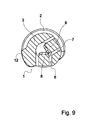
- Fig. 9 provides the embodiment according to Fig. 8 in a cross section through the spring arms 8, 9 represents.
- the spring arms 8, 9 are arranged at an angular distance of less than 180 degrees, here with 120 degrees to each other, so that the circumference of theticianschaftes 3 over a range of here 240 degrees is uninterrupted. This reduces the risk of tilting when screwing in the tension rivet.
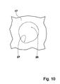
- Fig. 10 shows in a plan view of a belonging to the invention support member 17, an embodiment of a Spannnietabilityaus Principleung 26, which is circular over a circumference of about 270 degrees and over a circumference of about 90 degrees, a diameter of the Spannnietanalysisaus Principleung 26 opposite the circular portion of about 270 degrees has flared notch 27.
- This notch 27 is dimensioned so that unscrewing the above-described as releasable clamping rivets is possible if the end portions 13 of the threaded ring 12 preferably enter under a certain tilting of the relevant Spannn rivet in the notch 27.
Landscapes
- Engineering & Computer Science (AREA)
- General Engineering & Computer Science (AREA)
- Mechanical Engineering (AREA)
- Connection Of Plates (AREA)
- Clamps And Clips (AREA)
- Hooks, Suction Cups, And Attachment By Adhesive Means (AREA)
- Orthopedics, Nursing, And Contraception (AREA)
- Snaps, Bayonet Connections, Set Pins, And Snap Rings (AREA)
Priority Applications (1)
| Application Number | Priority Date | Filing Date | Title |
|---|---|---|---|
| PL11152032T PL2362107T3 (pl) | 2010-02-18 | 2011-01-25 | Nit mocujący |
Applications Claiming Priority (1)
| Application Number | Priority Date | Filing Date | Title |
|---|---|---|---|
| DE102010008457A DE102010008457A1 (de) | 2010-02-18 | 2010-02-18 | Spannniet |
Publications (3)
| Publication Number | Publication Date |
|---|---|
| EP2362107A2 true EP2362107A2 (fr) | 2011-08-31 |
| EP2362107A3 EP2362107A3 (fr) | 2012-10-31 |
| EP2362107B1 EP2362107B1 (fr) | 2015-03-04 |
Family
ID=43920282
Family Applications (1)
| Application Number | Title | Priority Date | Filing Date |
|---|---|---|---|
| EP11152032.6A Active EP2362107B1 (fr) | 2010-02-18 | 2011-01-25 | Rivet de serrage |
Country Status (4)
| Country | Link |
|---|---|
| EP (1) | EP2362107B1 (fr) |
| DE (1) | DE102010008457A1 (fr) |
| ES (1) | ES2536952T3 (fr) |
| PL (1) | PL2362107T3 (fr) |
Cited By (2)
| Publication number | Priority date | Publication date | Assignee | Title |
|---|---|---|---|---|
| US20130192038A1 (en) * | 2012-01-26 | 2013-08-01 | Empire Technology Development Llc | Sprung latch fastener |
| WO2019006480A1 (fr) * | 2017-07-06 | 2019-01-10 | Schluesselbauer Ulrich | Dispositif pour fixer un étrier dans un mur en béton |
Citations (2)
| Publication number | Priority date | Publication date | Assignee | Title |
|---|---|---|---|---|
| DE1625477A1 (de) | 1966-09-22 | 1972-04-13 | U S Expansion Bolt Co | Aufweitbares Befestigungsmittel |
| DE102005062242B3 (de) | 2005-12-24 | 2007-08-30 | A. Raymond Et Cie | Vorrichtung zum Befestigen eines Anbauteiles an einem Trägerteil |
Family Cites Families (7)
| Publication number | Priority date | Publication date | Assignee | Title |
|---|---|---|---|---|
| DE2341708A1 (de) * | 1972-08-31 | 1974-03-14 | Industrial Acoustics Co | Sicherheitsschraube |
| US4636121A (en) * | 1985-04-22 | 1987-01-13 | Miller Lillias S | Holding screw |
| EP0674082B1 (fr) * | 1994-03-23 | 1998-06-10 | A.T.P. Aluminio Tecnologia Y Producto S.A. | Dispositif d'ajustement, notamment pour cadres métalliques |
| JP4308569B2 (ja) * | 2003-05-08 | 2009-08-05 | 光洋器材株式会社 | ブラインドボルト |
| DE20311263U1 (de) * | 2003-07-22 | 2003-09-11 | Böllhoff GmbH, 33649 Bielefeld | Schraubverbindungsanordnung zum Verbinden zweier Bauteile |
| DE102004020039B3 (de) * | 2004-04-21 | 2005-09-08 | Rud-Kettenfabrik Rieger & Dietz Gmbh U. Co. | Tragbolzen |
| FR2882797B1 (fr) * | 2005-03-02 | 2007-05-25 | Itw De France Soc Par Actions | Attache adaptee a etre fixee dans une cavite de contour predetermine |
-
2010
- 2010-02-18 DE DE102010008457A patent/DE102010008457A1/de not_active Ceased
-
2011
- 2011-01-25 ES ES11152032.6T patent/ES2536952T3/es active Active
- 2011-01-25 PL PL11152032T patent/PL2362107T3/pl unknown
- 2011-01-25 EP EP11152032.6A patent/EP2362107B1/fr active Active
Patent Citations (2)
| Publication number | Priority date | Publication date | Assignee | Title |
|---|---|---|---|---|
| DE1625477A1 (de) | 1966-09-22 | 1972-04-13 | U S Expansion Bolt Co | Aufweitbares Befestigungsmittel |
| DE102005062242B3 (de) | 2005-12-24 | 2007-08-30 | A. Raymond Et Cie | Vorrichtung zum Befestigen eines Anbauteiles an einem Trägerteil |
Cited By (4)
| Publication number | Priority date | Publication date | Assignee | Title |
|---|---|---|---|---|
| US20130192038A1 (en) * | 2012-01-26 | 2013-08-01 | Empire Technology Development Llc | Sprung latch fastener |
| US9422958B2 (en) * | 2012-01-26 | 2016-08-23 | Empire Technology Development Llc | Sprung latch fastener |
| WO2019006480A1 (fr) * | 2017-07-06 | 2019-01-10 | Schluesselbauer Ulrich | Dispositif pour fixer un étrier dans un mur en béton |
| US11814900B2 (en) | 2017-07-06 | 2023-11-14 | Ulrich Schlüsselbauer | Device for securing a rung in a concrete wall |
Also Published As
| Publication number | Publication date |
|---|---|
| EP2362107B1 (fr) | 2015-03-04 |
| DE102010008457A1 (de) | 2011-09-08 |
| ES2536952T3 (es) | 2015-06-01 |
| PL2362107T3 (pl) | 2015-07-31 |
| EP2362107A3 (fr) | 2012-10-31 |
Similar Documents
| Publication | Publication Date | Title |
|---|---|---|
| EP3009694B1 (fr) | Élement de fixation et groupe d'element de fixation et element de reception | |
| DE102004036621B4 (de) | Spreizniet | |
| DE102010051372A1 (de) | Verbindungselement mit integrierter Schnappverbindung | |
| EP2513391B1 (fr) | Étai télescopique pour le secteur de la construction | |
| DE102008026215A1 (de) | Schraubfundament | |
| WO2014012730A1 (fr) | Tube réglable en longueur, en particulier pour des bâtons | |
| DE102009016633A1 (de) | Befestigungsmittel zur Vormontage eines stiftförmigen Verbindungsmittels in einer Durchgangsöffnung eines Bauteils | |
| EP3586018B1 (fr) | Dispositif de fixation et module de fixation | |
| DE102014008166A1 (de) | Hochfeste Befestigungsvorrichtung | |
| EP2261519A2 (fr) | Vis destinée à la fixation d'un premier composant sur un second composant | |
| EP1588975B1 (fr) | Attelage | |
| EP2598761B1 (fr) | Dispositif à monter sur un axe fileté | |
| WO2016041624A1 (fr) | Dispositif de fixation permettant de fixer un objet sanitaire | |
| EP2362107B1 (fr) | Rivet de serrage | |
| DE202009009291U1 (de) | Befestigungsanordnung und Clip hierfür | |
| DE202013101806U1 (de) | Drahtseilhaltevorrichtung | |
| DE202009004370U1 (de) | Längenverstellbarer Stock und Klemmvorrichtung dafür | |
| DE102011100247A1 (de) | Verbindungssystem | |
| DE102010061459B4 (de) | Spannschloss eines Ratschenlastspanners zum Verzurren von Ladungen | |
| EP3009583B1 (fr) | Pied de colonne | |
| DE102008046181A1 (de) | Antennenhalter für eine Satellitenschüssel | |
| DE7624442U1 (de) | Schnellverschluß, insbesondere für Einschübe in sog. 10 "-Schränke der Elektronik | |
| DE3732895C2 (fr) | ||
| DE202010004534U1 (de) | Befestigungseinrichtung mit Spannschraube | |
| DE102012223075B4 (de) | Verbindungssystem für ein Tragwerk |
Legal Events
| Date | Code | Title | Description |
|---|---|---|---|
| PUAI | Public reference made under article 153(3) epc to a published international application that has entered the european phase |
Free format text: ORIGINAL CODE: 0009012 |
|
| AK | Designated contracting states |
Kind code of ref document: A2 Designated state(s): AL AT BE BG CH CY CZ DE DK EE ES FI FR GB GR HR HU IE IS IT LI LT LU LV MC MK MT NL NO PL PT RO RS SE SI SK SM TR |
|
| AX | Request for extension of the european patent |
Extension state: BA ME |
|
| PUAL | Search report despatched |
Free format text: ORIGINAL CODE: 0009013 |
|
| AK | Designated contracting states |
Kind code of ref document: A3 Designated state(s): AL AT BE BG CH CY CZ DE DK EE ES FI FR GB GR HR HU IE IS IT LI LT LU LV MC MK MT NL NO PL PT RO RS SE SI SK SM TR |
|
| AX | Request for extension of the european patent |
Extension state: BA ME |
|
| RIC1 | Information provided on ipc code assigned before grant |
Ipc: F16B 5/06 20060101ALN20120926BHEP Ipc: F16B 19/10 20060101AFI20120926BHEP |
|
| 17P | Request for examination filed |
Effective date: 20130305 |
|
| GRAP | Despatch of communication of intention to grant a patent |
Free format text: ORIGINAL CODE: EPIDOSNIGR1 |
|
| RIC1 | Information provided on ipc code assigned before grant |
Ipc: F16B 5/06 20060101ALN20140916BHEP Ipc: F16B 19/10 20060101AFI20140916BHEP |
|
| INTG | Intention to grant announced |
Effective date: 20141017 |
|
| GRAS | Grant fee paid |
Free format text: ORIGINAL CODE: EPIDOSNIGR3 |
|
| RAP1 | Party data changed (applicant data changed or rights of an application transferred) |
Owner name: A. RAYMOND ET CIE |
|
| GRAA | (expected) grant |
Free format text: ORIGINAL CODE: 0009210 |
|
| AK | Designated contracting states |
Kind code of ref document: B1 Designated state(s): AL AT BE BG CH CY CZ DE DK EE ES FI FR GB GR HR HU IE IS IT LI LT LU LV MC MK MT NL NO PL PT RO RS SE SI SK SM TR |
|
| REG | Reference to a national code |
Ref country code: GB Ref legal event code: FG4D Free format text: NOT ENGLISH |
|
| REG | Reference to a national code |
Ref country code: CH Ref legal event code: EP |
|
| REG | Reference to a national code |
Ref country code: IE Ref legal event code: FG4D Free format text: LANGUAGE OF EP DOCUMENT: GERMAN |
|
| REG | Reference to a national code |
Ref country code: AT Ref legal event code: REF Ref document number: 714153 Country of ref document: AT Kind code of ref document: T Effective date: 20150415 |
|
| REG | Reference to a national code |
Ref country code: DE Ref legal event code: R096 Ref document number: 502011006081 Country of ref document: DE Effective date: 20150416 Ref country code: DE Ref legal event code: R082 Ref document number: 502011006081 Country of ref document: DE Representative=s name: RACKETTE PARTNERSCHAFT PATENTANWAELTE, DE |
|
| REG | Reference to a national code |
Ref country code: DE Ref legal event code: R082 Ref document number: 502011006081 Country of ref document: DE |
|
| REG | Reference to a national code |
Ref country code: ES Ref legal event code: FG2A Ref document number: 2536952 Country of ref document: ES Kind code of ref document: T3 Effective date: 20150601 |
|
| REG | Reference to a national code |
Ref country code: NL Ref legal event code: VDEP Effective date: 20150304 |
|
| PG25 | Lapsed in a contracting state [announced via postgrant information from national office to epo] |
Ref country code: SE Free format text: LAPSE BECAUSE OF FAILURE TO SUBMIT A TRANSLATION OF THE DESCRIPTION OR TO PAY THE FEE WITHIN THE PRESCRIBED TIME-LIMIT Effective date: 20150304 Ref country code: NO Free format text: LAPSE BECAUSE OF FAILURE TO SUBMIT A TRANSLATION OF THE DESCRIPTION OR TO PAY THE FEE WITHIN THE PRESCRIBED TIME-LIMIT Effective date: 20150604 Ref country code: FI Free format text: LAPSE BECAUSE OF FAILURE TO SUBMIT A TRANSLATION OF THE DESCRIPTION OR TO PAY THE FEE WITHIN THE PRESCRIBED TIME-LIMIT Effective date: 20150304 Ref country code: HR Free format text: LAPSE BECAUSE OF FAILURE TO SUBMIT A TRANSLATION OF THE DESCRIPTION OR TO PAY THE FEE WITHIN THE PRESCRIBED TIME-LIMIT Effective date: 20150304 Ref country code: LT Free format text: LAPSE BECAUSE OF FAILURE TO SUBMIT A TRANSLATION OF THE DESCRIPTION OR TO PAY THE FEE WITHIN THE PRESCRIBED TIME-LIMIT Effective date: 20150304 |
|
| REG | Reference to a national code |
Ref country code: PL Ref legal event code: T3 |
|
| REG | Reference to a national code |
Ref country code: LT Ref legal event code: MG4D |
|
| PG25 | Lapsed in a contracting state [announced via postgrant information from national office to epo] |
Ref country code: GR Free format text: LAPSE BECAUSE OF FAILURE TO SUBMIT A TRANSLATION OF THE DESCRIPTION OR TO PAY THE FEE WITHIN THE PRESCRIBED TIME-LIMIT Effective date: 20150605 Ref country code: LV Free format text: LAPSE BECAUSE OF FAILURE TO SUBMIT A TRANSLATION OF THE DESCRIPTION OR TO PAY THE FEE WITHIN THE PRESCRIBED TIME-LIMIT Effective date: 20150304 Ref country code: RS Free format text: LAPSE BECAUSE OF FAILURE TO SUBMIT A TRANSLATION OF THE DESCRIPTION OR TO PAY THE FEE WITHIN THE PRESCRIBED TIME-LIMIT Effective date: 20150304 |
|
| PG25 | Lapsed in a contracting state [announced via postgrant information from national office to epo] |
Ref country code: NL Free format text: LAPSE BECAUSE OF FAILURE TO SUBMIT A TRANSLATION OF THE DESCRIPTION OR TO PAY THE FEE WITHIN THE PRESCRIBED TIME-LIMIT Effective date: 20150304 |
|
| PG25 | Lapsed in a contracting state [announced via postgrant information from national office to epo] |
Ref country code: SK Free format text: LAPSE BECAUSE OF FAILURE TO SUBMIT A TRANSLATION OF THE DESCRIPTION OR TO PAY THE FEE WITHIN THE PRESCRIBED TIME-LIMIT Effective date: 20150304 Ref country code: EE Free format text: LAPSE BECAUSE OF FAILURE TO SUBMIT A TRANSLATION OF THE DESCRIPTION OR TO PAY THE FEE WITHIN THE PRESCRIBED TIME-LIMIT Effective date: 20150304 Ref country code: RO Free format text: LAPSE BECAUSE OF FAILURE TO SUBMIT A TRANSLATION OF THE DESCRIPTION OR TO PAY THE FEE WITHIN THE PRESCRIBED TIME-LIMIT Effective date: 20150304 Ref country code: PT Free format text: LAPSE BECAUSE OF FAILURE TO SUBMIT A TRANSLATION OF THE DESCRIPTION OR TO PAY THE FEE WITHIN THE PRESCRIBED TIME-LIMIT Effective date: 20150706 |
|
| PG25 | Lapsed in a contracting state [announced via postgrant information from national office to epo] |
Ref country code: IS Free format text: LAPSE BECAUSE OF FAILURE TO SUBMIT A TRANSLATION OF THE DESCRIPTION OR TO PAY THE FEE WITHIN THE PRESCRIBED TIME-LIMIT Effective date: 20150704 |
|
| REG | Reference to a national code |
Ref country code: DE Ref legal event code: R097 Ref document number: 502011006081 Country of ref document: DE |
|
| PLBE | No opposition filed within time limit |
Free format text: ORIGINAL CODE: 0009261 |
|
| STAA | Information on the status of an ep patent application or granted ep patent |
Free format text: STATUS: NO OPPOSITION FILED WITHIN TIME LIMIT |
|
| REG | Reference to a national code |
Ref country code: FR Ref legal event code: PLFP Year of fee payment: 6 |
|
| PG25 | Lapsed in a contracting state [announced via postgrant information from national office to epo] |
Ref country code: DK Free format text: LAPSE BECAUSE OF FAILURE TO SUBMIT A TRANSLATION OF THE DESCRIPTION OR TO PAY THE FEE WITHIN THE PRESCRIBED TIME-LIMIT Effective date: 20150304 |
|
| 26N | No opposition filed |
Effective date: 20151207 |
|
| PG25 | Lapsed in a contracting state [announced via postgrant information from national office to epo] |
Ref country code: SI Free format text: LAPSE BECAUSE OF FAILURE TO SUBMIT A TRANSLATION OF THE DESCRIPTION OR TO PAY THE FEE WITHIN THE PRESCRIBED TIME-LIMIT Effective date: 20150304 |
|
| PG25 | Lapsed in a contracting state [announced via postgrant information from national office to epo] |
Ref country code: BE Free format text: LAPSE BECAUSE OF NON-PAYMENT OF DUE FEES Effective date: 20160131 |
|
| PG25 | Lapsed in a contracting state [announced via postgrant information from national office to epo] |
Ref country code: LU Free format text: LAPSE BECAUSE OF FAILURE TO SUBMIT A TRANSLATION OF THE DESCRIPTION OR TO PAY THE FEE WITHIN THE PRESCRIBED TIME-LIMIT Effective date: 20160125 |
|
| REG | Reference to a national code |
Ref country code: CH Ref legal event code: PL |
|
| PG25 | Lapsed in a contracting state [announced via postgrant information from national office to epo] |
Ref country code: MC Free format text: LAPSE BECAUSE OF FAILURE TO SUBMIT A TRANSLATION OF THE DESCRIPTION OR TO PAY THE FEE WITHIN THE PRESCRIBED TIME-LIMIT Effective date: 20150304 |
|
| PG25 | Lapsed in a contracting state [announced via postgrant information from national office to epo] |
Ref country code: LI Free format text: LAPSE BECAUSE OF NON-PAYMENT OF DUE FEES Effective date: 20160131 Ref country code: CH Free format text: LAPSE BECAUSE OF NON-PAYMENT OF DUE FEES Effective date: 20160131 |
|
| REG | Reference to a national code |
Ref country code: IE Ref legal event code: MM4A |
|
| REG | Reference to a national code |
Ref country code: FR Ref legal event code: PLFP Year of fee payment: 7 |
|
| PG25 | Lapsed in a contracting state [announced via postgrant information from national office to epo] |
Ref country code: IE Free format text: LAPSE BECAUSE OF NON-PAYMENT OF DUE FEES Effective date: 20160125 |
|
| REG | Reference to a national code |
Ref country code: AT Ref legal event code: MM01 Ref document number: 714153 Country of ref document: AT Kind code of ref document: T Effective date: 20160125 |
|
| PG25 | Lapsed in a contracting state [announced via postgrant information from national office to epo] |
Ref country code: AT Free format text: LAPSE BECAUSE OF NON-PAYMENT OF DUE FEES Effective date: 20160125 |
|
| PG25 | Lapsed in a contracting state [announced via postgrant information from national office to epo] |
Ref country code: MT Free format text: LAPSE BECAUSE OF FAILURE TO SUBMIT A TRANSLATION OF THE DESCRIPTION OR TO PAY THE FEE WITHIN THE PRESCRIBED TIME-LIMIT Effective date: 20150304 |
|
| REG | Reference to a national code |
Ref country code: FR Ref legal event code: PLFP Year of fee payment: 8 |
|
| PG25 | Lapsed in a contracting state [announced via postgrant information from national office to epo] |
Ref country code: CY Free format text: LAPSE BECAUSE OF FAILURE TO SUBMIT A TRANSLATION OF THE DESCRIPTION OR TO PAY THE FEE WITHIN THE PRESCRIBED TIME-LIMIT Effective date: 20150304 Ref country code: HU Free format text: LAPSE BECAUSE OF FAILURE TO SUBMIT A TRANSLATION OF THE DESCRIPTION OR TO PAY THE FEE WITHIN THE PRESCRIBED TIME-LIMIT; INVALID AB INITIO Effective date: 20110125 Ref country code: SM Free format text: LAPSE BECAUSE OF FAILURE TO SUBMIT A TRANSLATION OF THE DESCRIPTION OR TO PAY THE FEE WITHIN THE PRESCRIBED TIME-LIMIT Effective date: 20150304 |
|
| PG25 | Lapsed in a contracting state [announced via postgrant information from national office to epo] |
Ref country code: MK Free format text: LAPSE BECAUSE OF FAILURE TO SUBMIT A TRANSLATION OF THE DESCRIPTION OR TO PAY THE FEE WITHIN THE PRESCRIBED TIME-LIMIT Effective date: 20150304 Ref country code: TR Free format text: LAPSE BECAUSE OF FAILURE TO SUBMIT A TRANSLATION OF THE DESCRIPTION OR TO PAY THE FEE WITHIN THE PRESCRIBED TIME-LIMIT Effective date: 20150304 |
|
| PG25 | Lapsed in a contracting state [announced via postgrant information from national office to epo] |
Ref country code: BG Free format text: LAPSE BECAUSE OF FAILURE TO SUBMIT A TRANSLATION OF THE DESCRIPTION OR TO PAY THE FEE WITHIN THE PRESCRIBED TIME-LIMIT Effective date: 20150304 |
|
| PG25 | Lapsed in a contracting state [announced via postgrant information from national office to epo] |
Ref country code: AL Free format text: LAPSE BECAUSE OF FAILURE TO SUBMIT A TRANSLATION OF THE DESCRIPTION OR TO PAY THE FEE WITHIN THE PRESCRIBED TIME-LIMIT Effective date: 20150304 |
|
| PGFP | Annual fee paid to national office [announced via postgrant information from national office to epo] |
Ref country code: ES Payment date: 20210326 Year of fee payment: 11 |
|
| PGFP | Annual fee paid to national office [announced via postgrant information from national office to epo] |
Ref country code: GB Payment date: 20220119 Year of fee payment: 12 |
|
| PGFP | Annual fee paid to national office [announced via postgrant information from national office to epo] |
Ref country code: PL Payment date: 20220117 Year of fee payment: 12 Ref country code: IT Payment date: 20220120 Year of fee payment: 12 |
|
| REG | Reference to a national code |
Ref country code: ES Ref legal event code: FD2A Effective date: 20230329 |
|
| PG25 | Lapsed in a contracting state [announced via postgrant information from national office to epo] |
Ref country code: ES Free format text: LAPSE BECAUSE OF NON-PAYMENT OF DUE FEES Effective date: 20220126 |
|
| P01 | Opt-out of the competence of the unified patent court (upc) registered |
Effective date: 20230524 |
|
| GBPC | Gb: european patent ceased through non-payment of renewal fee |
Effective date: 20230125 |
|
| PG25 | Lapsed in a contracting state [announced via postgrant information from national office to epo] |
Ref country code: GB Free format text: LAPSE BECAUSE OF NON-PAYMENT OF DUE FEES Effective date: 20230125 |
|
| PG25 | Lapsed in a contracting state [announced via postgrant information from national office to epo] |
Ref country code: IT Free format text: LAPSE BECAUSE OF NON-PAYMENT OF DUE FEES Effective date: 20230125 |
|
| PG25 | Lapsed in a contracting state [announced via postgrant information from national office to epo] |
Ref country code: PL Free format text: LAPSE BECAUSE OF NON-PAYMENT OF DUE FEES Effective date: 20230125 |
|
| PG25 | Lapsed in a contracting state [announced via postgrant information from national office to epo] |
Ref country code: PL Free format text: LAPSE BECAUSE OF NON-PAYMENT OF DUE FEES Effective date: 20230125 |
|
| PGFP | Annual fee paid to national office [announced via postgrant information from national office to epo] |
Ref country code: DE Payment date: 20260121 Year of fee payment: 16 |
|
| PGFP | Annual fee paid to national office [announced via postgrant information from national office to epo] |
Ref country code: FR Payment date: 20260123 Year of fee payment: 16 |
|
| PGFP | Annual fee paid to national office [announced via postgrant information from national office to epo] |
Ref country code: CZ Payment date: 20260120 Year of fee payment: 16 |