EP2362140A2 - Procédé de combustion de combustible liquide et appareil - Google Patents
Procédé de combustion de combustible liquide et appareil Download PDFInfo
- Publication number
- EP2362140A2 EP2362140A2 EP11001180A EP11001180A EP2362140A2 EP 2362140 A2 EP2362140 A2 EP 2362140A2 EP 11001180 A EP11001180 A EP 11001180A EP 11001180 A EP11001180 A EP 11001180A EP 2362140 A2 EP2362140 A2 EP 2362140A2
- Authority
- EP
- European Patent Office
- Prior art keywords
- oxidant gas
- liquid fuel
- end portion
- conduit
- gas passage
- Prior art date
- Legal status (The legal status is an assumption and is not a legal conclusion. Google has not performed a legal analysis and makes no representation as to the accuracy of the status listed.)
- Withdrawn
Links
Images

Classifications
-
- F—MECHANICAL ENGINEERING; LIGHTING; HEATING; WEAPONS; BLASTING
- F23—COMBUSTION APPARATUS; COMBUSTION PROCESSES
- F23D—BURNERS
- F23D11/00—Burners using a direct spraying action of liquid droplets or vaporised liquid into the combustion space
- F23D11/10—Burners using a direct spraying action of liquid droplets or vaporised liquid into the combustion space the spraying being induced by a gaseous medium, e.g. water vapour
- F23D11/101—Burners using a direct spraying action of liquid droplets or vaporised liquid into the combustion space the spraying being induced by a gaseous medium, e.g. water vapour medium and fuel meeting before the burner outlet
- F23D11/102—Burners using a direct spraying action of liquid droplets or vaporised liquid into the combustion space the spraying being induced by a gaseous medium, e.g. water vapour medium and fuel meeting before the burner outlet in an internal mixing chamber
-
- F—MECHANICAL ENGINEERING; LIGHTING; HEATING; WEAPONS; BLASTING
- F23—COMBUSTION APPARATUS; COMBUSTION PROCESSES
- F23D—BURNERS
- F23D11/00—Burners using a direct spraying action of liquid droplets or vaporised liquid into the combustion space
- F23D11/10—Burners using a direct spraying action of liquid droplets or vaporised liquid into the combustion space the spraying being induced by a gaseous medium, e.g. water vapour
-
- F—MECHANICAL ENGINEERING; LIGHTING; HEATING; WEAPONS; BLASTING
- F23—COMBUSTION APPARATUS; COMBUSTION PROCESSES
- F23D—BURNERS
- F23D11/00—Burners using a direct spraying action of liquid droplets or vaporised liquid into the combustion space
- F23D11/36—Details
- F23D11/38—Nozzles; Cleaning devices therefor
-
- F—MECHANICAL ENGINEERING; LIGHTING; HEATING; WEAPONS; BLASTING
- F23—COMBUSTION APPARATUS; COMBUSTION PROCESSES
- F23D—BURNERS
- F23D11/00—Burners using a direct spraying action of liquid droplets or vaporised liquid into the combustion space
- F23D11/36—Details
- F23D11/40—Mixing tubes; Burner heads
Definitions
- atomizer nozzles Use of atomizer nozzles is known in the combustion art as illustrated in U.S. Pat. Nos. 5,547,368 , 5,567,141 , 5,393,220 , 5,617,997 , and 7,500,849 incorporated herein by reference in their entireties. As described in U.S. Pat. No. 5,547,368 , atomizer nozzles are used in industrial melting furnaces for such diverse products as metals, glass, ceramic materials, and the like.
- the nozzles can be grouped in two major groups:
- the primary oxidizer cools the atomizing nozzle.
- the primary oxidizer is air
- cooling is accomplished due to the large volume of air (the primary oxidizer) that is needed and provided for complete combustion.
- oxy-fuel burners which are burners utilizing a primary oxidizer with a higher O 2 concentration than air
- cooling of the atomizing nozzle via the reduced volume of the primary oxidizer may be unsatisfactory.
- the present invention relates to an apparatus for combustion of a liquid fuel.
- the apparatus for combustion may be a liquid fuel atomizer.
- the liquid fuel atomizer comprises (a) an outer conduit of generally cylindrical shape having an atomizing gas inlet end portion and an atomizing gas discharge end portion, (b) an inner conduit of generally cylindrical shape having a liquid fuel inlet end portion and a liquid fuel discharge end portion, the inner conduit disposed within said outer conduit and forming an atomizing gas passage between said outer conduit and said inner conduit, the atomizing gas passage extending from the atomizing gas inlet end portion to the atomizing gas discharge end portion, and (c) a spray tip having an inlet end portion and a discharge end portion, the inlet end portion of the spray tip joined to the atomizing gas discharge end portion of the outer conduit.
- the spray tip has (i) a mixing chamber disposed to receive a liquid fuel from the liquid fuel discharge end portion of the inner conduit and disposed to receive an atomizing gas from the atomizing gas discharge end portion of the atomizing gas passage, and (ii) an orifice at the outlet end portion of the spray tip, the orifice disposed to receive the liquid fuel and the atomizing gas from the mixing chamber and for discharging the liquid fuel and the atomizing gas from the spray tip as an atomized liquid fuel.
- the inner conduit has a plurality of external fins at the liquid fuel discharge end portion of the inner conduit wherein at least some of the plurality of external fins contact an inner surface of the inlet end portion of the spray tip.
- the orifice of the liquid fuel atomizer may be an elongated slotted orifice.
- the plurality of external fins may have a converging external taper which converges in the direction of the liquid fuel discharge end portion.
- the spray tip may have a converging internal taper at the inlet end portion which converges in the direction of the outlet end portion, the internal taper generally complementary to the external taper of the plurality of external fins.
- the plurality of external fins may be longitudinal fins.
- the plurality of external fins may e longitudinal fins and the ratio of length of the plurality of external fins to outer diameter of the outer conduit may be 0.1 to 3.0.
- the plurality of external fins may be spiral fins.
- the plurality of external fins may number from 3 to 20 or from 6 to 10.
- the outer conduit may have a ratio of conduit wall thickness to conduit outer diameter of 0.1 to 0.2.
- the apparatus may have a ratio of atomizing gas passage hydraulic diameter to outer diameter of the outer conduit of 0.05 to 0.25.
- the apparatus may have a ratio of inner conduit wall thickness to inner conduit outer diameter of 0.2 to 0.7 at an inner conduit cross section having the plurality of external fins.
- the apparatus may have 0.1 ⁇ N ⁇ S P ⁇ 0.9 , where N is the quantity of external fins of the plurality of external fins, S is the mean arc length of the external fins of the plurality of external fins, and P is the inner perimeter of the outer conduit at an outer conduit cross section adjacent the plurality of external fins.
- the inlet end portion of the spray tip may be joined to the atomizing gas discharge end portion of the outer conduit by a weld joint.
- the weld joint may have a thickness of greater than 25% to 100% of the wall thickness of the outer conduit.
- the mixing chamber may have a converging internal taper proximate the orifice which converges in the direction of the orifice.
- the apparatus may further comprise a first oxidant gas conduit section defining a first oxidant gas passage, the first oxidant gas passage having a first oxidant gas passage inlet end portion and a first oxidant gas passage discharge end portion for discharging a first oxidant gas stream; and wherein the outer conduit is disposed in spaced relation to the first oxidant gas conduit with at least a part of the outer conduit disposed within the oxidant gas passage.
- the apparatus may further comprise a second oxidant gas conduit section defining a second oxidant gas passage proximate the first oxidant gas passage, the second oxidant gas passage for discharging a second oxidant gas stream.
- the apparatus may further comprise an oxidant inlet manifold in fluid flow communication with the first oxidant gas passage and the second oxidant gas passage; and a staging valve in downstream fluid flow communication with the oxidant inlet manifold and in upstream fluid flow communication with the second oxidant gas passage for regulating a flow of the second oxidant gas stream to the second oxidant gas passage.
- the apparatus for combustion may be an oxy-fuel burner.
- the burner comprises (I) a first oxidant gas conduit section defining a first oxidant gas passage, the first oxidant gas passage having a first oxidant gas passage inlet end portion and a first oxidant gas passage discharge end portion for discharging a first oxidant gas stream, and (II) a liquid fuel atomizer disposed in spaced relation to the first oxidant gas conduit with at least a part of the liquid fuel atomizer disposed within the oxidant gas passage.
- the liquid fuel atomizer comprises (a) an outer conduit of generally cylindrical shape having an atomizing gas inlet end portion and an atomizing gas discharge end portion, (b) an inner conduit of generally cylindrical shape having a liquid fuel inlet end portion and a liquid fuel discharge end portion, the inner conduit disposed within said outer conduit and forming an atomizing gas passage between said outer conduit and said inner conduit, the atomizing gas passage extending from the atomizing gas inlet end portion to the atomizing gas discharge end portion, and (c) a spray tip having an inlet end portion and a discharge end portion, the inlet end portion of the spray tip joined to the atomizing gas discharge end portion of the outer conduit.
- the spray tip has (i) a mixing chamber disposed to receive a liquid fuel from the liquid fuel discharge end portion of the inner conduit and disposed to receive an atomizing gas from the atomizing gas discharge end portion of the atomizing gas passage, and (ii) an orifice at the outlet end portion of the spray tip, the orifice disposed to receive the liquid fuel and the atomizing gas from the mixing chamber and for discharging the liquid fuel and the atomizing gas from the spray tip as an atomized liquid fuel into the first oxidant gas stream.
- the inner conduit has a plurality of external fins at the liquid fuel discharge end portion of the inner conduit wherein at least some of the plurality of external fins contact an inner surface of the inlet end portion of the spray tip.
- the orifice may be an elongated slotted orifice.
- the plurality of external fins may have a converging external taper which converges in the direction of the liquid fuel discharge end portion and wherein the spray tip has a converging internal taper at the inlet end portion which converges in the direction of the outlet end portion.
- the internal taper is generally complementary to the external taper of the plurality of external fins.
- the plurality of external fins may be longitudinal fins.
- the apparatus may have a ratio of length of the plurality of external fins to outer diameter of the outer conduit of 0.1 to 3.0.
- the plurality of external fins may be spiral fins.
- the plurality of external fins may number from 3 to 20 or from 6 to 10.
- the outer conduit may have a ratio of conduit wall thickness to conduit outer diameter of 0.1 to 0.2.
- the apparatus may have a ratio of atomizing gas passage hydraulic diameter to outer diameter of the outer conduit of 0.05 to 0.25.
- the apparatus may have a ratio of inner conduit wall thickness to inner conduit outer diameter of 0.2 to 0.7 at an inner conduit cross section having the plurality of external fins.
- the inlet end portion of the spray tip may be joined to the atomizing gas discharge end portion of the outer conduit by a weld joint.
- the weld joint may have a thickness of 50% to 100% of the wall thickness of the outer conduit.
- the mixing chamber may have a converging internal taper adjacent the orifice which converges in the direction of the orifice.
- the burner may further comprise a second oxidant gas conduit section defining a second oxidant gas passage proximate the first oxidant gas passage, the second oxidant gas passage for discharging a second oxidant gas stream.
- the second oxidant gas passage may be located above or below the first oxidant gas passage.
- the first oxidant gas passage may have a cross-sectional shape with a width and height of different dimensions, and wherein the first oxidant gas passage has a width to height ratio of 5 to 30, and wherein the second oxidant gas passage has a cross-sectional shape with a width and height of different dimensions, and wherein the second oxidant gas passage has a width to height ratio of 5 to 30.
- the burner may further comprise an oxidant inlet manifold in fluid flow communication with the first oxidant gas passage and the second oxidant gas passage, and a staging valve in downstream fluid flow communication with the oxidant inlet manifold and in upstream fluid flow communication with the first and second oxidant gas passage for regulating the flow distribution between the first and second oxidant gas streams to the first and second oxidant gas passages, respectively.
- the burner may further comprise an oxidant inlet plenum in upstream fluid flow communication of the first oxidant gas passage, at least a portion of the oxidant inlet plenum being spaced around at least a portion of the liquid fuel atomizer, and an oxidant diffuser located in upstream fluid flow communication of said oxidant inlet plenum.
- the present invention also relates to a method for combusting a liquid fuel.
- the method comprises (A) providing a burner where the burner comprises (I) a first oxidant gas conduit section defining an oxidant gas passage, the first oxidant gas passage having a first oxidant gas passage inlet end portion and a first oxidant gas passage discharge end portion for discharging a first oxidant gas stream, and (II) a liquid fuel atomizer disposed within the oxidant gas passage.
- the liquid fuel atomizer comprises (a) an outer conduit of generally cylindrical shape having an atomizing gas inlet end portion and an atomizing gas discharge end portion, (b) an inner conduit of generally cylindrical shape and having a liquid fuel inlet end portion and a liquid fuel discharge end portion, the inner conduit disposed within said outer conduit and forming an atomizing gas passage between said outer conduit and said inner conduit the atomizing gas passage extending from the atomizing gas inlet end portion to the atomizing gas discharge end portion, and (c) a spray tip having an inlet end portion and a discharge end portion, the inlet end portion of the spray tip joined to the atomizing gas discharge end portion of the outer conduit.
- the spray tip has (i) a mixing chamber disposed to receive a liquid fuel from the liquid fuel discharge end portion of the inner conduit and disposed to receive an atomizing gas from the atomizing gas discharge end portion of the atomizing gas passage, and (ii) an orifice at the outlet end portion of the spray tip, the orifice disposed to receive the liquid fuel and the atomizing gas from the mixing chamber and for discharging the liquid fuel and the atomizing gas from the spray tip as an atomized liquid fuel into the first oxidant gas stream
- the inner conduit has a plurality of external fins at the liquid fuel discharge end portion of the inner conduit wherein at least some of the plurality of external fins contact an inner surface of the inlet end portion of the spray tip.
- the method further comprises (B) passing a first oxidant gas through the first oxidant gas passage thereby discharging the first oxidant gas stream from the first oxidant gas passage discharge end portion, (C) passing the liquid fuel through the inner conduit and into the mixing chamber and passing the atomizing gas through the atomizing gas passage and into the mixing chamber thereby forming a mixture of the liquid fuel and the atomizing gas, (D) passing the mixture of the liquid fuel and the atomizing gas through the orifice thereby discharging the mixture of the liquid fuel and the atomizing gas from the mixing chamber as an atomized liquid fuel into the first oxidant gas stream, and (E) combusting at least a portion of the atomized liquid fuel with at least a portion of the first oxidant gas stream thereby forming a flame.
- the burner used in the method may further comprise a second oxidant gas conduit section defining a second oxidant gas passage.
- the second oxidant gas passage may be proximate and above or below the first oxidant gas passage.
- the second oxidant gas passage is for discharging a second oxidant gas stream.
- the method may further comprise passing the second oxidant gas stream through the second oxidant gas passage thereby discharging the second oxidant gas stream below the flame, and combusting at least another portion of the liquid fuel with at least a portion of the second oxidant gas stream.
- the mixture of the liquid fuel and the atomizing gas may have a mean residence time in the mixing chamber of from 70 to 3200 microseconds, from 160 to 2400 microseconds, or from 250 to 1600 microseconds.
- the mixture of the liquid fuel and the atomizing gas may be discharged from the spray tip with a velocity, V 1
- the first oxidant gas may be discharged from the first oxidant gas conduit discharge end portion with a velocity, v 2 , wherein 1 ⁇ v 1 v 2 ⁇ 100.
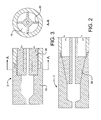
- FIG. 1 is a cross sectional view of a liquid fuel atomizer with external fins on the inner conduit where the external fins are tapered over a portion of the external fins.
- FIG. 2 is a cross sectional view of a liquid fuel atomizer with external fins on the inner conduit where the external fins are tapered over the entire length of the external fins.
- FIG. 3 is a cross sectional view of a liquid fuel atomizer with external fins on the inner conduit where the external fins are not tapered.
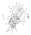
- FIG. 4 shows a perspective view of a burner that incorporates the liquid fuel atomizer.
- the present disclosure relates to an apparatus for combustion of a liquid fuel.
- the apparatus may be a liquid fuel atomizer suitable for use in a burner.
- the liquid fuel atomizer 1 comprises an outer conduit 10 of generally cylindrical shape having an atomizing gas inlet end portion 12 and an atomizing gas discharge end portion 14.
- the liquid fuel atomizer 1 also comprises an inner conduit 20 of generally cylindrical shape having a liquid fuel inlet end portion 22 and a liquid fuel discharge end portion 24.
- the inner conduit 20 is disposed within the outer conduit 10 and forms an atomizing gas passage 16 between the outer conduit 10 and the inner conduit 20.
- the atomizing gas passage 16 extends from the atomizing gas inlet end portion 12 to the atomizing gas discharge end portion 14. Since the article "a" means one or more when applied to the passage feature, one or more passages may be formed between the outer conduit 10 and the inner conduit 20.
- the passage 16 may be divided and/or divided and recombined as it extends from the atomizing gas inlet end portion 12 and the atomizing gas discharge end portion 14, but nevertheless provides a continuous flow path from the atomizing gas inlet end portion 12 to the atomizing gas discharge end portion.
- the ratio of the conduit wall thickness to the outer diameter of the outer conduit 10 may be from 0.034 to 0.35 or from 0.1 to 0.2, or from 0.14 to 0.18.
- the benefit of the ratio of the conduit wall thickness to the outer diameter of the outer conduit of from 0.1 to 0.2 when compared to smaller ratios is two-fold. First, it provides an increased cross sectional area for heat to be conducted away from the hot spot located on the outside surface of the liquid fuel atomizer 1, which is typically located somewhere between the discharge end portion 34 of the spray tip 30 and three outer conduit 10 diameters upstream. Secondly, it allows for a thicker joint through the wall thickness of the outer conduit 10 which provides an increased cross sectional area for heat to be conducted away from the hot spot located on the outside surface of the liquid fuel atomizer 1.
- the outer conduit 10 may have a first longitudinal axis and the inner conduit 20 may have a second longitudinal axis wherein the first longitudinal axis and the second longitudinal axis are substantially coaxial.
- substantially coaxial means that the axes are coincident, parallel and within 5% of the inner conduit inner diameter of being coincident, or slightly askew where the axes are parallel to within 2° and within 5% of the inner conduit inner diameter at the atomizing gas discharge end portion 14 and liquid fuel discharge end portion 24.
- the inner conduit 20 has an effective inner diameter measured on the inside of the conduit 20 near or at the outlet end of the conduit 20 that is adjacent to the mixing chamber 36.
- the effective diameter is the same as the diameter.
- an effective diameter can be calculated, the effective diameter giving the same cross-sectional area as the cross sectional area of the non-circular conduit.
- the effective inner diameter of the inner conduit 20 may be from 1.27 mm to 12.7 mm.
- the liquid fuel atomizer 1 also comprises a spray tip 30 having an inlet end portion 32 and a discharge end portion 34.
- the inlet end portion 32 of the spray tip 30 is joined to the atomizing gas discharge end portion 14 of the outer conduit 10 by a join 18.
- the join 18 may be a weld joint, press fit join, threaded joint or other suitable join known in the art.
- the join 18 is preferably a weld joint.
- a weld joint may provide better heat conduction for cooling the spray tip.
- the weld joint may have a thickness of greater than 50% to 100% of the wall thickness of the outer conduit 10. It may be desirable to make the weld joint as thick as practical. Large weld joints require that the thickness of one of the outer conduit and the spray tip at the overlap region be thin and therefore more prone to deformation during welding, which is not desirable.
- the inner conduit may be removably connected to the outer conduit at the inlet end portion by a threaded or other suitable connection (not shown) which permits removal of the inner conduit from the liquid fuel atomizer for cleaning.
- the spray tip 30 has a mixing chamber 36 disposed to receive a liquid fuel from the liquid fuel discharge end portion 24 of the inner conduit 20 and disposed to receive an atomizing gas from the atomizing gas passage 16.
- the mixing chamber 36 is intermediate the inlet end portion 32 and the discharge end portion 34.
- the spray tip 30 also has an orifice 38 at the discharge end portion 34 of the spray tip 30.
- the orifice 38 is disposed to receive the liquid fuel and the atomizing gas from the mixing chamber 36 and for discharging the liquid fuel and the atomizing gas from the spray tip 30 as an atomized liquid fuel.
- the mixing chamber 36 has an effective diameter and a length.
- the length of the mixing chamber is measured from the outlet end of the inner conduit 20 to the chamber-side of the mixing chamber orifice 38.
- the mixing chamber 36 is shown as cylindrical, it is not limited to a cylindrical shape and/or circular cross section. In case the cross section of the mixing chamber is circular, the effective diameter is the same as the diameter. In case the cross section of the mixing chamber is non-circular, an effective diameter can be calculated, said effective diameter giving the same cross sectional area.
- the mixing chamber 36 has a length that is 2 times or less than 2 times of the effective inner diameter of the inner conduit 20.
- the length of the mixing chamber may be from 0.5 to 2 times greater than the effective inner diameter of the inner conduit 20 for sufficient mixing of the atomizing gas and liquid fuel prior to being discharged through the flame-shaping orifice 38.
- the mixing chamber length may be from 1 to 2 times, or about 1.7 times the effective inner diameter of the inner conduit 20.
- the liquid fuel and the atomizing gas should remain in the mixing chamber for a mean residence time from 70 to 3200 microseconds, from 160 to 2400 microseconds, or from 250 to 1600 microseconds.
- the mixing chamber may have a converging internal taper 37 which converges in the direction of the orifice 38.
- a converging internal taper provides a benefit of easier cleaning.
- a cleaning tool shaped like the end of a drill bit with complementary shape to the converging internal taper may be used to clean the spray tip.
- the mixing chamber may have a tapered portion located towards the orifice, which is spherical-shaped, or elliptical-shaped, or the like and may extend over more or less of the length of the mixing chamber than as shown.
- the emulsion chamber is shown with a constant cross-section over a majority of the mixing chamber in FIG. 1 , the mixing chamber is not limited to a constant cross-section.
- the mixing chamber may be shaped to reduce in cross-section over a majority or all of its length from the fuel inlet to the orifice, thereby providing a tapered mixing chamber.
- the inner conduit 20 has a plurality of external fins 26 at the liquid fuel discharge end portion 24 of the inner conduit 20 wherein at least some of the plurality of external fins 26 contact an inner surface 35 of the inlet end portion 32 of the spray tip 30. All of the plurality of external fins 26 may contact the inner surface 35 of the inlet end portion 32 of the spray tip 30. External fins are outward protrusions which define grooves on the outer surface of the inner conduit 20. The external fins 26 contacting the inner surface of the spray tip has the benefit of providing an additional heat conduction path from the spray tip and setting the prescribed gap between the liquid fuel discharge end portion 22 of the inner conduit 20 and the inlet end portion 32 of the spray tip 30 for the atomizing gas passage 16. The gap is set by the external fins and is not adjustable, except by modifying the external fins.
- the plurality of external fins 26 may number from 3 to 20 or from 6 to 10.
- the plurality of external fins 26 may be longitudinal fins, where the fins are straight and have an axis which is parallel to the longitudinal axis of the inner conduit 20.
- the plurality of external fins 26 may be spiral or helical as they move down the length of the inner conduit.
- the external fins may also be straight for a portion and spiral or helical near the outlet end portion 24 of the inner conduit 20.
- the plurality of external fins 26 may have a converging external taper which converges in the direction of the liquid fuel discharge end portion 24.
- the spray tip 30 may have a converging internal taper at the inlet end portion 32 which converges in the direction of the discharge end portion 34.
- the internal taper of the spray tip 30 may be generally complementary to the external taper of the plurality of external fins 26.
- the converging external taper may be over part of the length of the plurality of external fins 26.
- the converging external taper may be over all of the length of the plurality of external fins 26.
- the plurality of external fins 26 may be without a converging external taper.
- the spray tip 30, too, may be without a converging internal taper at the inlet end portion 32.
- the liquid fuel atomizer may be used to atomize any liquid fuel used in industrial furnace applications, for example, No. 1 distillate oil, No. 2 distillate fuel oil, diesel fuel, biodiesel and it's by-products (such as glycerol), kerosene, No. 4 fuel oil, No. 5 residual oil, No. 6 residual fuel oil, Bunker-C type fuel oil and others known to a person of ordinary skill in the art.
- the atomizing gas may be any known atomizing gas used in industrial furnace applications, for example, air, natural gas, industrial grade oxygen, oxygen-enriched air, propane, nitrogen, carbon dioxide, hydrogen, or a mixture of two or more of these gases.
- the orifice 38 may be an elongated slotted orifice, which acts to form a flattened spray pattern.
- a slotted orifice is a slot opening having a width dimension and a height dimension, where the width dimension is greater than the height dimension. The width may range from 3 mm to 25.4 mm and the height may range from 0.75 to 7.62 mm.
- the slot cross-section may be rectangular, oval, or other suitable non-circular shape.
- An elongated slotted orifice has a length dimension as well, where the length dimension is at least 2 times the hydraulic diameter. The length dimension may be 2 to 10 times the hydraulic diameter.
- the cross-section of the slot may vary along the length, for example, the width dimension may increase in the direction of flow thereby having a divergence angle.
- a length dimension greater than 2 times the hydraulic diameter allows the spray pattern to be shaped by the orifice shape and divergence angle.
- the outer conduit 10, inner conduit 20, and spray tip 30 can be made from any suitable material, for example, stainless steel and constructed using methods known in the art.
- the plurality of external fins 26 may be machined into the surface of the inner conduit 20 by cutting grooves into the outer surface.
- the apparatus for combustion of a liquid fuel may be a burner with the liquid fuel atomizer as described above.
- the burner may be adapted to operate at a firing rate of between 0.10 and 12 MW or between 0.25 and 6 MW.
- the burner 60 comprises a first oxidant gas conduit section 40 defining a first oxidant gas passage 54, the first oxidant gas passage 54 having a first oxidant gas passage inlet end portion 44 and a first oxidant gas passage discharge end portion 46 for discharging a first oxidant gas stream, and a liquid fuel atomizer 5 disposed in spaced relation to the oxidant gas conduit section 40 with at least part of the liquid fuel atomizer 5 disposed within the first oxidant gas passage 54.
- the liquid fuel atomizer 5 is as described above and may comprise any of the liquid fuel atomizer features described herein.
- the first oxidant gas may be any oxidant gas suitable for combustion, for example, air, oxygen-enriched air, and industrial grade oxygen.
- the first oxidant gas passage 54 may have a cross-sectional shape with a width and height of different dimensions.
- the first oxidant gas passage 54 may have a width to height ratio of 5 to 30.
- the first oxidant gas passage 54 may have a cross section of non-circular shape and each cross section may be characterized by a center point or centroid, where centroid has the usual geometric definition.
- the gas passage 54 may be further characterized by a longitudinal axis defined as a straight line orthogonal to the passage cross sections and connecting the centroids of the passage cross sections.
- the burner 60 may further comprise a second oxidant gas conduit section 70 defining a second oxidant gas passage 56 for discharging a second oxidant gas stream for so-called oxidant staging.
- the second oxidant gas passage 56 is proximate the first oxidant gas passage 54 and may be located below the first oxidant gas passage 54.
- the second oxidant gas passage 56 may have a cross-sectional shape with a width and height of different dimensions.
- the second oxidant gas passage 56 may have a width to height ratio of 5 to 30.
- the second oxidant gas passage 56 may have a cross section of non-circular shape and each cross section may be characterized by a center point or centroid, where centroid has the usual geometric definition.
- the second oxidant gas passage 56 may be further characterized by a longitudinal axis defined as a straight line orthogonal to the passage cross sections and connecting the centroids of the passage cross sections.
- the longitudinal axis of the first oxidant gas passage 54 and the longitudinal axis of the second oxidant gas passage 56 may be substantially parallel.
- the second oxidant gas may be any oxidant gas suitable for combustion, for example, air, oxygen-enriched air, and industrial grade oxygen.
- the first oxidant gas and the second oxidant gas may be the same composition, coming from the same source.
- the first oxidant gas conduit section 40 and the second oxidant gas conduit section 70 may be constructed from separate and distinct conduits or constructed from a single block of material, e.g. a burner block, as shown in FIG. 4.
- FIG. 4 shows the first oxidant gas passage 54 and the second oxidant gas passage 56 formed in a common burner block 50.
- the burner block 50 may comprise the first oxidant gas conduit section 40 and the second oxidant gas conduit section 70.
- the burner may be constructed to convey the same oxidant gas to the first oxidant gas passage 54 and the second oxidant gas passage 56 so that the second oxidant gas stream has the same concentration of oxygen as the first oxidant gas stream.
- the burner may be constructed to convey a different oxidant gas to the second oxidant gas passage 56 than to the first oxidant gas passage 54 so that the second oxidant gas stream has a different concentration of oxygen than the first oxidant gas stream.
- the burner 60 may further comprise an oxidant inlet manifold 57.
- Oxidant gas flows through the oxidant inlet manifold 57 and eventually to the first oxidant gas passage 54 and the second oxidant gas passage 56.
- the oxidant inlet manifold 57 is in upstream fluid flow communication with the first oxidant gas passage 54 and the second oxidant gas passage 56.
- a staging valve 64 may be used to divert or regulate the flow of the oxidant gas to the second oxidant gas passage 56.
- the staging valve 64 is in downstream fluid flow communication with the oxidant inlet manifold 57 and in upstream fluid flow communication with the first and second oxidant gas passage 56.
- the burner 60 may further comprise an oxidant inlet plenum 82 in upstream fluid flow communication of the first oxidant gas passage 54.
- the oxidant inlet plenum may be spaced around at least a portion of the liquid fuel atomizer, and at least a portion of the first oxidant gas passage 54 may be spaced around the spray tip.
- the burner may further comprise a diffuser 80 located upstream of the oxidant plenum 82. The purpose of this diffuser is to assist in distributing the oxidant flow entering the oxidant inlet plenum.
- the discharge end of the spray tip 30 may be mounted flush with the hot face 52 of the burner block 50, or recessed inside of the first oxidant gas passage 54. Recessing the spray tip 30 into the burner block 50 will help to maintain cooler operating temperature of the mixing chamber. However, the extent to which the spray tip 30 may be recessed will depend on the operating conditions of the burner 60, as described below.
- the present disclosure relates to a method for combusting a liquid fuel using the burner as described herein.
- the burner may be operated at a firing rate of between 0.10 and 12 MW or between 0.25 and 6 MW.
- the method for combusting a liquid fuel comprises providing a burner as described herein with a liquid fuel atomizer as described herein.
- the burner and liquid fuel atomizer may comprise any of the respective burner or liquid fuel atomizer features described herein.
- the method comprises passing a first oxidant gas through the first oxidant gas conduit section 40 thereby discharging a first oxidant gas stream from the first oxidant gas conduit discharge end portion 46.
- the method further comprises passing the liquid fuel through the inner conduit 20 and into the mixing chamber 36 and passing the atomizing gas through the atomizing gas passage 16 and into the mixing chamber 36 thereby forming a mixture of the liquid fuel and the atomizing gas.
- the method then further comprises passing the mixture of the liquid fuel and the atomizing gas through the orifice 38 thereby discharging the mixture of the liquid fuel and the atomizing gas from the mixing chamber 36 as an atomized liquid fuel into the first oxidant gas stream.
- the method further comprises combusting at least a portion of the liquid fuel with at least a portion of the first oxidant gas stream thereby forming a flame.
- the method may also include oxidant staging.
- a second oxidant gas may be passed through a second oxidant passage 56 thereby discharging the second oxidant gas stream below the flame and combusting at least a portion of the liquid fuel with at least a portion of the second oxidant gas stream.
- the mixture of the liquid fuel and the atomizing gas may have a mean residence time in the mixing chamber of from 70 to 3200 microseconds, from 160 to 2400 microseconds, or from 250 to 1600 microseconds.
- the mean residence time is calculated by dividing the overall mixing chamber volume (over the emulsion chamber length defined earlier) by the emulsion mixture volumetric flow rate.
- the emulsion mixture volumetric flow rate is calculated by adding the volumetric flow rates of both the liquid fuel and atomizing gas. Since the atomizing gas is compressible, the actual volumetric flow rate for the gas is obtained by correcting for pressure.
- the liquid fuel flow rate is 70 liters/hour
- the atomizing gas flow rate is 11 normal meters cubed per hour (Nm 3 /h)
- the pressure in the emulsion chamber is 2.4 bar
- the temperature in the mixing chamber is 373K
- the mixture of the liquid fuel and the atomizing gas may be discharged from the spray tip with a velocity, v 1
- the first oxidant gas may be discharged from the first oxidant gas conduit discharge end portion with a velocity, v 2 , wherein 1 ⁇ v 1 v 2 ⁇ 100 .
- the fuel droplets first evaporate and it is the evaporation of the droplet (prior to combustion) which is the rate limiting step in the combustion process which proceeds as a diffusion flame around the evaporating drop (Lefebvre, "Atomization and Sprays," p. 309, Hemisphere Publishing, 1989).
- v 1 the mixture of the liquid fuel and the atomizing gas velocity
- v 2 the mixture of the liquid fuel and the atomizing gas will tend to draw the first oxidant gas into the region containing the liquid fuel droplets without significantly affecting the shape of the region containing the liquid fuel droplets.
- the flame shape is not significantly affected by the flow of oxidant gas, but is instead dictated more by the design of the liquid fuel atomizer.
- the flame envelope is a strong function of the spray pattern of the atomizer.
- the ratio v 1 v 2 increases beyond 100, either the atomizing gas velocity, v 1 , is very large, or the first oxidant gas velocity, v 2 , is very small, or both.
- the mixture of the liquid fuel and the atomizing gas velocity, v 1 is very large, this has the disadvantage of requiring high supply pressures of the atomizing gas and liquid fuel.
- the first oxidant gas velocity, v 2 is very small, this has the affect of reducing the extent to which the first oxidant gas will provide beneficial cooling to the spray tip, and may result in uneven distribution of the first oxidant gas around the spray tip, 30, and outer conduit, 10. For this reason a ratio v 1 v 2 above 100 is not desirable.
- the region containing liquid fuel droplets, and therefore the flame begins to change shape and in some instances will oscillate. This increases the likelihood of having the region of liquid fuel droplets, and therefore the flame, impinge on the inside surface of the first oxidant gas passage, 54, of the burner block, 50, resulting in damage to the burner block, 50. In addition, this will significantly restrict the extent to which the lance can be recessed inside the of the burner block.
- the mixture velocity, v 1 is calculated by adding the volumetric flow rates of both the liquid fuel and atomizing gas and dividing the result by the cross sectional area of the orifice. As described earlier, since the atomizing gas is compressible, the actual volumetric flow rate for the gas is obtained by correcting for pressure.
- Example 1 the effect of changing the operating conditions on the mixing chamber maximum temperature was determined, using the nozzles of Cases 1 and 2 as described in Table 3. Two operating conditions were chosen. In the first operating condition, the oil flow to the burner was 106 1/hr and the atomizing flow was 3.94 Nm 3 /hr. The proportion of oxidant through first oxidant passage was 30%, with the balance of oxidant required for stoichiometric combustion flowing through the second oxidant gas passage. In the second operating condition, the oil flow to the burner was 265 1/hr and the atomizing flow was 3.94 Nm 3 /hr. The proportion of oxidant through first oxidant passage was 50%, with the balance of oxidant required for stoichiometric combustion flowing through the second oxidant gas passage. The furnace temperature for both cases was 1649°C.
- the maximum predicted temperature inside of the mixing chamber was 532°C for the lower oil flow rate and lower oxidant flow rate in the first oxidant gas passage.
- the maximum predicted temperature inside of the mixing chamber was 377°C for the higher oil flow rate and higher proportion of oxidant flow rate in the first oxidant gas passage.
- the maximum predicted temperature inside of the mixing chamber was 433°C for the lower oil flow rate and lower oxidant flow rate in the first oxidant gas passage.
- the maximum predicted temperature inside of the mixing chamber was 306°C for the higher oil flow rate and higher proportion of oxidant flow rate in the first oxidant gas passage.
- the most optimal operation, particularly for glass melting, is typically with maximum degree of oxidant staging possible (i.e. with a greater proportion of oxidant directed to the second oxidant passage), with the benefits of increased direction radiation (more heat from the flame directed downward toward the glass, less heat directed from the flame toward the crown of the furnace), glass quality, and decreased NOx emissions as described, for example, in US Patent 7,390,189 .
- Example 2 Effect of contact of the plurality of external fins to the inner surface of the inlet end portion of the spray tip
- Example 3- Effect of the weld joint thickness as a proportion of the wall thickness of the outer conduit
- the outer conduit also receives a significant portion of heat via radiant heat transfer from the furnace to its outer surface.
- heat is removed from the outer conduit by several mechanisms: heat convection via flow of the oxidant through the first oxidant passage, which surrounds the outer conduit; heat conduction along the length of the outer conduit, as well as radial conduction through the conduit wall; heat convection via flow of the atomizing gas which is in fluid communication with the inner surface of the outer conduit.
- the convection always helps to cool the chamber temperature, but whether the conduction along the length of the outer conduit would do the same depends on which direction the heat is conducted.
- the spray tip is effectively cooled by the liquid fuel and atomizing gas at the inner surface of the emulsion chamber, and the hottest spot occurs at the outer surface of the outer conduit (10) instead of at the nozzle tip.
- the contact between the plurality of external fins and the inner surface of the inlet end portion of the spray tip further decreases the tip temperature.
- the reason that the maximum mixing chamber temperature is increased when the thickness of the weld is increased is because the thicker welds allows for a greater amount of heat to be conducted axially along the outer conduit wall from the conduit wall hot spot to the spray tip and into the mixing chamber.
- Example 4 Effect of the ratio of conduit wall thickness to outer conduit outer diameter
- the first change that was made was that the length of the plurality of external fins was significantly decreased such that there is a large area of surface between the outer conduit and the cooling air.
- the second change was that, the hydraulic diameter of the annular space between the inside surface of the outer conduit, and the outside surface of the inner conduit was decreased by more than 50% from Case 3 to Case 4 by increasing the inner conduit outer diameter (and wall thickness to maintain the same inner conduit inner diameter).
- the aspect ratio of the slots in Case 4 was changed from a narrow deep slot, to a relatively square slot.
- the aspect ratio (height to width) of the slots in Case 3 was 2.74 and in Case 4 was 0.97.
- the external fins create a barrier to convective heat transfer between the atomizing gas and the inner surface of the outer conduit because there is essentially no flow in the tolerance gap between the outer fin surfaces and the inner surface of the outer conduit.
- the fins do not play a significant role in radial conduction away (radially inward) from the outer conduit because there is not intimate contact between the outer surfaces of the external fins and the inner surface of the outer conduit. This is in contrast to the intimate and beneficial contact between the outer surfaces of the external fins and the inner surface of the spray tip described earlier.
- N is the quantity of external fins of the plurality of external fins
- S is the mean arc length of the external fins of the plurality of external fins
- P is the inner perimeter of the outer conduit at an outer conduit cross section adjacent the plurality of external fins.
- the thicker wall of the inner conduit for case 4 allows for greater conduction from the mixing chamber along the length of the inner conduit away from the mixing chamber, thereby lowering the mixing chamber temperature.
- the mixing chamber is well below the temperature at which coke will form, and the maximum outer conduit temperature is below the temperature range of 430-900°C where aqueous corrosion due to carbide precipitation (particularly chromium carbide) at the grain boundaries is a concern for most common alloys such as 316, 304, and 310 stainless steels ( Roberge, P.R., Handbook of Corrosion Engineering, McGraw-Hill ⁇ 2000. Page 712 ).
- the present atomizer had 8 external fins on the outer surface of the inner conduit.
- thermocouple was used to measure the surface temperature of the inside surface of the mixing chamber. Air was passed through the atomizing gas passage at a rate of 5.2 Nm 3 /h (3.3 scfm). No liquid fuel was passed through the atomizer. A furnace was heated to about 1150°C (2100°F). The different atomizers were inserted an equal depth into the furnace such that the tip of the atomizer was protruding into the furnace. The temperature of the surface inside the mixing chamber was measured. The inner surface temperature of the mixing chamber of the '849 atomizer was about 350°C with an average furnace temperature of about 1184°C. The inner surface temperature of the mixing chamber of the present atomizer 236°C with an average furnace temperature of about 1197°C.
Landscapes
- Engineering & Computer Science (AREA)
- Chemical & Material Sciences (AREA)
- Combustion & Propulsion (AREA)
- Mechanical Engineering (AREA)
- General Engineering & Computer Science (AREA)
- Nozzles For Spraying Of Liquid Fuel (AREA)
- Nozzles (AREA)
- Spray-Type Burners (AREA)
Applications Claiming Priority (1)
| Application Number | Priority Date | Filing Date | Title |
|---|---|---|---|
| US12/708,166 US8172566B2 (en) | 2010-02-18 | 2010-02-18 | Liquid fuel combustion process and apparatus |
Publications (1)
| Publication Number | Publication Date |
|---|---|
| EP2362140A2 true EP2362140A2 (fr) | 2011-08-31 |
Family
ID=43983567
Family Applications (1)
| Application Number | Title | Priority Date | Filing Date |
|---|---|---|---|
| EP11001180A Withdrawn EP2362140A2 (fr) | 2010-02-18 | 2011-02-14 | Procédé de combustion de combustible liquide et appareil |
Country Status (12)
| Country | Link |
|---|---|
| US (1) | US8172566B2 (fr) |
| EP (1) | EP2362140A2 (fr) |
| JP (1) | JP5551633B2 (fr) |
| KR (1) | KR101188492B1 (fr) |
| CN (1) | CN102192502B (fr) |
| BR (1) | BRPI1100147A2 (fr) |
| CA (1) | CA2731625C (fr) |
| MX (1) | MX2011001740A (fr) |
| MY (1) | MY156139A (fr) |
| RU (1) | RU2518710C2 (fr) |
| TW (1) | TWI439642B (fr) |
| ZA (1) | ZA201101277B (fr) |
Cited By (2)
| Publication number | Priority date | Publication date | Assignee | Title |
|---|---|---|---|---|
| WO2015009300A1 (fr) * | 2013-07-18 | 2015-01-22 | Johns Manville | Brûleur de combustion refroidi par fluide et procédé de fabrication du dit brûleur |
| EP2703713A3 (fr) * | 2012-08-31 | 2017-11-08 | Robert Bosch Gmbh | Brûleur à prémélange à l'huile |
Families Citing this family (11)
| Publication number | Priority date | Publication date | Assignee | Title |
|---|---|---|---|---|
| US20110296953A1 (en) * | 2010-06-08 | 2011-12-08 | Bloom Engineering Company, Inc. | Method of Co-Firing Raw Glycerin in a Melting Furnace |
| US20130048539A1 (en) * | 2011-08-23 | 2013-02-28 | Marathon Oil Canada Corporation | Methods and Systems for Upgrading Hydrocarbon |
| EP2703339A1 (fr) * | 2012-09-04 | 2014-03-05 | Casale Chemicals S.A. | Brûleur pour la production de gaz de synthèse |
| CN104100970B (zh) * | 2013-04-12 | 2017-04-12 | 气体产品与化学公司 | 氧‑固体燃料喷燃器 |
| US9803555B2 (en) * | 2014-04-23 | 2017-10-31 | General Electric Company | Fuel delivery system with moveably attached fuel tube |
| BR112016004754B1 (pt) | 2014-05-02 | 2022-06-28 | Air Products And Chemicals, Inc. | Queimador com monitoramento |
| US20150316256A1 (en) * | 2014-05-02 | 2015-11-05 | Air Products And Chemicals, Inc. | Oil Burner With Monitoring |
| CN108531737B (zh) * | 2018-05-08 | 2024-02-27 | 中国恩菲工程技术有限公司 | 一种含铜污泥和线路板的综合处理系统 |
| JP6963838B2 (ja) * | 2019-04-23 | 2021-11-10 | 株式会社イスト | 燃焼装置 |
| CN110906324B (zh) * | 2019-12-25 | 2025-04-01 | 江苏徐工工程机械研究院有限公司 | 燃烧器、燃烧器油枪和燃烧器油枪喷嘴 |
| CN116677996A (zh) * | 2023-06-27 | 2023-09-01 | 乔治洛德方法研究和开发液化空气有限公司 | 用于燃烧器的气体分布部件 |
Citations (6)
| Publication number | Priority date | Publication date | Assignee | Title |
|---|---|---|---|---|
| US5393220A (en) | 1993-12-06 | 1995-02-28 | Praxair Technology, Inc. | Combustion apparatus and process |
| US5547368A (en) | 1993-03-01 | 1996-08-20 | Air Products And Chemicals, Inc. | Process and device for combustion-enhanced atomization and vaporization of liquid fuels |
| US5567141A (en) | 1994-12-30 | 1996-10-22 | Combustion Tec, Inc. | Oxy-liquid fuel combustion process and apparatus |
| US5617997A (en) | 1994-06-13 | 1997-04-08 | Praxair Technology, Inc. | Narrow spray angle liquid fuel atomizers for combustion |
| US7390189B2 (en) | 2004-08-16 | 2008-06-24 | Air Products And Chemicals, Inc. | Burner and method for combusting fuels |
| US7500849B2 (en) | 2004-01-16 | 2009-03-10 | Air Products And Chemicals, Inc. | Emulsion atomizer nozzle, and burner, and method for oxy-fuel burner applications |
Family Cites Families (33)
| Publication number | Priority date | Publication date | Assignee | Title |
|---|---|---|---|---|
| US1100141A (en) * | 1912-03-27 | 1914-06-16 | Machinery And Electrical Company | Oil-burner. |
| US1559625A (en) * | 1924-02-21 | 1925-11-03 | Paul W Kutis | Burner |
| US1564064A (en) * | 1924-12-18 | 1925-12-01 | Louey Migel | Burner |
| US1813083A (en) * | 1928-03-14 | 1931-07-07 | Serge M Pyankow | Oil burner |
| US2050368A (en) * | 1934-02-26 | 1936-08-11 | Neely George Leonard | Spray nozzle |
| US2762656A (en) * | 1951-10-11 | 1956-09-11 | Reginald P Fraser | Liquid atomizer |
| US2984421A (en) * | 1958-08-11 | 1961-05-16 | Sarah A Hession | Adjustable aerosol device |
| US3013732A (en) * | 1959-09-01 | 1961-12-19 | Parker Hannifin Corp | Fuel injection nozzle |
| US3717306A (en) * | 1971-03-10 | 1973-02-20 | Hushon R | Nozzle for spraying foaming materials |
| JPS5141693B1 (fr) * | 1971-05-24 | 1976-11-11 | ||
| SU1417560A1 (ru) * | 1986-08-20 | 1997-09-20 | Л.И. Пищенко | Форсунка |
| JP2749964B2 (ja) * | 1990-06-20 | 1998-05-13 | 三菱重工業株式会社 | バーナ装置 |
| US5092760A (en) | 1990-08-01 | 1992-03-03 | Maxon Corporation | Oxygen-fuel burner assembly and operation |
| US5199866A (en) * | 1992-03-30 | 1993-04-06 | Air Products And Chemicals, Inc. | Adjustable momentum self-cooled oxy/fuel burner for heating in high temperature environments |
| US5307635A (en) * | 1992-10-29 | 1994-05-03 | United Technologies Corporation | Fuel nozzle with combined radial and axial bellows |
| US5732885A (en) | 1994-10-07 | 1998-03-31 | Spraying Systems Co. | Internal mix air atomizing spray nozzle |
| US5575637A (en) | 1994-11-04 | 1996-11-19 | Air Products And Chemicals, Inc. | Method and device for low-NOx high efficiency heating in high temperature furnaces |
| ES2220965T3 (es) * | 1995-07-17 | 2004-12-16 | L'air Liquide, S.A. A Directoire Et Conseil De Surv. Pour L'etude Et L'exploitat. Procedes G. Claude | Proceso de combustion y aparato para el mismo con inyeccion separada de las corrientes de combustible y oxidante. |
| US5611682A (en) | 1995-09-05 | 1997-03-18 | Air Products And Chemicals, Inc. | Low-NOx staged combustion device for controlled radiative heating in high temperature furnaces |
| US5975886A (en) * | 1996-11-25 | 1999-11-02 | L'air Liquide, Societe Anonyme Pour L'etude Et L'exploitation Des Procedes Georges Claude | Combustion process and apparatus therefore containing separate injection of fuel and oxidant streams |
| US6334579B1 (en) * | 1999-02-18 | 2002-01-01 | Honeywell Measurex Devron Inc. | Air atomizing nozzle |
| JP2994382B1 (ja) * | 1999-03-01 | 1999-12-27 | 中外炉工業株式会社 | 排ガス自己循環式低NOxバ―ナ |
| FR2794221B1 (fr) * | 1999-05-31 | 2001-08-24 | Pillard Chauffage | PERFECTIONNEMENTS AUX BRULEURS A COMBUSTIBLE LIQUIDE A BASSE EMISSION DE NOx ET DE POUSSIERES, ET AUX ATOMISEURS |
| US6174161B1 (en) | 1999-07-30 | 2001-01-16 | Air Products And Chemical, Inc. | Method and apparatus for partial oxidation of black liquor, liquid fuels and slurries |
| CA2323032A1 (fr) | 1999-10-18 | 2001-04-18 | Air Products And Chemicals, Inc. | Methode et appareil de securite pour la combustion a l'oxygaz a l'aide de la combustion d'un melange air-combustible |
| DE19961947A1 (de) | 1999-12-22 | 2001-06-28 | Bosch Gmbh Robert | Vorrichtung und Verfahren zur Erzeugung eines Reduktionsmittel-Luftgemisches |
| JP2001263609A (ja) * | 2000-03-21 | 2001-09-26 | Sumikin Manegement Co Ltd | 外部混合式液体燃料バーナ |
| US6688534B2 (en) * | 2001-03-07 | 2004-02-10 | Delavan Inc | Air assist fuel nozzle |
| ITMI20012784A1 (it) * | 2001-12-21 | 2003-06-21 | Nuovo Pignone Spa | Iniettore migliorato di combustibile liquido per bruciatori di turbine a gas |
| RU2298730C1 (ru) * | 2005-09-14 | 2007-05-10 | Владимир Викторович Черниченко | Соосно-струйная форсунка |
| US7506822B2 (en) * | 2006-04-24 | 2009-03-24 | General Electric Company | Slurry injector and methods of use thereof |
| JP4697090B2 (ja) * | 2006-08-11 | 2011-06-08 | Jx日鉱日石エネルギー株式会社 | 二流体噴霧バーナ |
| US8454354B2 (en) * | 2008-05-08 | 2013-06-04 | Air Products And Chemicals, Inc. | Highly radiative burner and combustion process |
-
2010
- 2010-02-18 US US12/708,166 patent/US8172566B2/en not_active Expired - Fee Related
-
2011
- 2011-01-31 MY MYPI2011000450A patent/MY156139A/en unknown
- 2011-02-11 CA CA2731625A patent/CA2731625C/fr not_active Expired - Fee Related
- 2011-02-14 TW TW100104833A patent/TWI439642B/zh active
- 2011-02-14 MX MX2011001740A patent/MX2011001740A/es active IP Right Grant
- 2011-02-14 EP EP11001180A patent/EP2362140A2/fr not_active Withdrawn
- 2011-02-15 BR BRPI1100147-0A patent/BRPI1100147A2/pt not_active IP Right Cessation
- 2011-02-17 ZA ZA2011/01277A patent/ZA201101277B/en unknown
- 2011-02-17 RU RU2011106121/06A patent/RU2518710C2/ru not_active IP Right Cessation
- 2011-02-17 JP JP2011032226A patent/JP5551633B2/ja active Active
- 2011-02-18 CN CN201110040493.8A patent/CN102192502B/zh active Active
- 2011-02-18 KR KR1020110014814A patent/KR101188492B1/ko active Active
Patent Citations (6)
| Publication number | Priority date | Publication date | Assignee | Title |
|---|---|---|---|---|
| US5547368A (en) | 1993-03-01 | 1996-08-20 | Air Products And Chemicals, Inc. | Process and device for combustion-enhanced atomization and vaporization of liquid fuels |
| US5393220A (en) | 1993-12-06 | 1995-02-28 | Praxair Technology, Inc. | Combustion apparatus and process |
| US5617997A (en) | 1994-06-13 | 1997-04-08 | Praxair Technology, Inc. | Narrow spray angle liquid fuel atomizers for combustion |
| US5567141A (en) | 1994-12-30 | 1996-10-22 | Combustion Tec, Inc. | Oxy-liquid fuel combustion process and apparatus |
| US7500849B2 (en) | 2004-01-16 | 2009-03-10 | Air Products And Chemicals, Inc. | Emulsion atomizer nozzle, and burner, and method for oxy-fuel burner applications |
| US7390189B2 (en) | 2004-08-16 | 2008-06-24 | Air Products And Chemicals, Inc. | Burner and method for combusting fuels |
Non-Patent Citations (2)
| Title |
|---|
| ROBERGE, P.R.: "Handbook of Corrosion Engineering", 2000, MCGRAW-HILL, pages: 712 |
| SPEIGHT, JAMES G.: "Handbook of Petroleum Analysis", 2001, JOHN WILEY & SONS, pages: 216 |
Cited By (2)
| Publication number | Priority date | Publication date | Assignee | Title |
|---|---|---|---|---|
| EP2703713A3 (fr) * | 2012-08-31 | 2017-11-08 | Robert Bosch Gmbh | Brûleur à prémélange à l'huile |
| WO2015009300A1 (fr) * | 2013-07-18 | 2015-01-22 | Johns Manville | Brûleur de combustion refroidi par fluide et procédé de fabrication du dit brûleur |
Also Published As
| Publication number | Publication date |
|---|---|
| CA2731625A1 (fr) | 2011-08-18 |
| US8172566B2 (en) | 2012-05-08 |
| KR20110095217A (ko) | 2011-08-24 |
| JP5551633B2 (ja) | 2014-07-16 |
| MY156139A (en) | 2016-01-15 |
| CN102192502B (zh) | 2014-11-26 |
| BRPI1100147A2 (pt) | 2012-07-31 |
| CA2731625C (fr) | 2013-08-06 |
| ZA201101277B (en) | 2012-11-28 |
| TW201131122A (en) | 2011-09-16 |
| RU2518710C2 (ru) | 2014-06-10 |
| KR101188492B1 (ko) | 2012-10-05 |
| JP2011169578A (ja) | 2011-09-01 |
| MX2011001740A (es) | 2011-08-30 |
| US20110200955A1 (en) | 2011-08-18 |
| CN102192502A (zh) | 2011-09-21 |
| RU2011106121A (ru) | 2012-08-27 |
| TWI439642B (zh) | 2014-06-01 |
Similar Documents
| Publication | Publication Date | Title |
|---|---|---|
| US8172566B2 (en) | Liquid fuel combustion process and apparatus | |
| JP4976357B2 (ja) | 含酸素燃料バーナー用途のためのエマルジョン噴霧器ノズル、バーナー及び方法 | |
| US5567141A (en) | Oxy-liquid fuel combustion process and apparatus | |
| US5617997A (en) | Narrow spray angle liquid fuel atomizers for combustion | |
| CN101779082A (zh) | 低NOx混合喷射器 | |
| US5547368A (en) | Process and device for combustion-enhanced atomization and vaporization of liquid fuels | |
| US20110000261A1 (en) | Low Maintenance Burner for Glass Forehearth | |
| US5685706A (en) | V-jet atomizer | |
| EP2405197A1 (fr) | Procédé de combustion à maintenance réduire approprié à l'utilisation dans un avant-creuset de four à verre | |
| JP4382477B2 (ja) | 噴射装置並びにその使用方法 | |
| GB2140910A (en) | Heating of enclosures | |
| RU2256847C1 (ru) | Горелка для жидкого топлива | |
| JP3035564B2 (ja) | 酸素富化オイル燃焼方法 | |
| US20240375130A1 (en) | Atomizer nozzle |
Legal Events
| Date | Code | Title | Description |
|---|---|---|---|
| PUAI | Public reference made under article 153(3) epc to a published international application that has entered the european phase |
Free format text: ORIGINAL CODE: 0009012 |
|
| AK | Designated contracting states |
Kind code of ref document: A2 Designated state(s): AL AT BE BG CH CY CZ DE DK EE ES FI FR GB GR HR HU IE IS IT LI LT LU LV MC MK MT NL NO PL PT RO RS SE SI SK SM TR |
|
| AX | Request for extension of the european patent |
Extension state: BA ME |
|
| STAA | Information on the status of an ep patent application or granted ep patent |
Free format text: STATUS: THE APPLICATION HAS BEEN PUBLISHED |
|
| STAA | Information on the status of an ep patent application or granted ep patent |
Free format text: STATUS: THE APPLICATION IS DEEMED TO BE WITHDRAWN |
|
| 18D | Application deemed to be withdrawn |
Effective date: 20160901 |