EP2362157A1 - Collecteur solaire - Google Patents
Collecteur solaire Download PDFInfo
- Publication number
- EP2362157A1 EP2362157A1 EP10154031A EP10154031A EP2362157A1 EP 2362157 A1 EP2362157 A1 EP 2362157A1 EP 10154031 A EP10154031 A EP 10154031A EP 10154031 A EP10154031 A EP 10154031A EP 2362157 A1 EP2362157 A1 EP 2362157A1
- Authority
- EP
- European Patent Office
- Prior art keywords
- adhesive
- absorber element
- line system
- curing
- line
- Prior art date
- Legal status (The legal status is an assumption and is not a legal conclusion. Google has not performed a legal analysis and makes no representation as to the accuracy of the status listed.)
- Withdrawn
Links
- 239000000853 adhesive Substances 0.000 claims abstract description 111
- 230000001070 adhesive effect Effects 0.000 claims abstract description 111
- 238000000034 method Methods 0.000 claims abstract description 62
- 238000002156 mixing Methods 0.000 claims abstract description 13
- 230000005855 radiation Effects 0.000 claims abstract description 11
- 238000012546 transfer Methods 0.000 claims abstract description 11
- 239000006096 absorbing agent Substances 0.000 claims description 97
- 238000004519 manufacturing process Methods 0.000 claims description 13
- 239000013464 silicone adhesive Substances 0.000 claims description 10
- 239000006163 transport media Substances 0.000 claims description 10
- 239000002318 adhesion promoter Substances 0.000 claims description 4
- 239000002609 medium Substances 0.000 claims description 4
- 238000001723 curing Methods 0.000 description 28
- 238000003466 welding Methods 0.000 description 16
- 239000000463 material Substances 0.000 description 15
- 238000012545 processing Methods 0.000 description 12
- 150000001875 compounds Chemical class 0.000 description 7
- 238000005516 engineering process Methods 0.000 description 6
- 238000005304 joining Methods 0.000 description 5
- 238000004140 cleaning Methods 0.000 description 4
- 229910052751 metal Inorganic materials 0.000 description 4
- 239000002184 metal Substances 0.000 description 4
- 238000005476 soldering Methods 0.000 description 4
- 238000011161 development Methods 0.000 description 3
- 230000018109 developmental process Effects 0.000 description 3
- 239000011521 glass Substances 0.000 description 3
- 239000000919 ceramic Substances 0.000 description 2
- 239000011248 coating agent Substances 0.000 description 2
- 238000000576 coating method Methods 0.000 description 2
- 238000007872 degassing Methods 0.000 description 2
- 230000001419 dependent effect Effects 0.000 description 2
- 239000012530 fluid Substances 0.000 description 2
- 239000007788 liquid Substances 0.000 description 2
- 235000011837 pasties Nutrition 0.000 description 2
- 239000004033 plastic Substances 0.000 description 2
- 229920003023 plastic Polymers 0.000 description 2
- 239000004848 polyfunctional curative Substances 0.000 description 2
- 229920001296 polysiloxane Polymers 0.000 description 2
- 230000008092 positive effect Effects 0.000 description 2
- 229910000838 Al alloy Inorganic materials 0.000 description 1
- 239000004821 Contact adhesive Substances 0.000 description 1
- RYGMFSIKBFXOCR-UHFFFAOYSA-N Copper Chemical compound [Cu] RYGMFSIKBFXOCR-UHFFFAOYSA-N 0.000 description 1
- 229910000881 Cu alloy Inorganic materials 0.000 description 1
- 229910000831 Steel Inorganic materials 0.000 description 1
- 238000004026 adhesive bonding Methods 0.000 description 1
- 229910045601 alloy Inorganic materials 0.000 description 1
- 239000000956 alloy Substances 0.000 description 1
- 239000007767 bonding agent Substances 0.000 description 1
- 238000001816 cooling Methods 0.000 description 1
- 239000010949 copper Substances 0.000 description 1
- 230000005611 electricity Effects 0.000 description 1
- 238000005265 energy consumption Methods 0.000 description 1
- 230000007613 environmental effect Effects 0.000 description 1
- 150000002118 epoxides Chemical class 0.000 description 1
- 230000009931 harmful effect Effects 0.000 description 1
- 238000005338 heat storage Methods 0.000 description 1
- 238000009434 installation Methods 0.000 description 1
- 238000002955 isolation Methods 0.000 description 1
- 229910001092 metal group alloy Inorganic materials 0.000 description 1
- 239000000203 mixture Substances 0.000 description 1
- 238000012544 monitoring process Methods 0.000 description 1
- 238000010943 off-gassing Methods 0.000 description 1
- 230000000704 physical effect Effects 0.000 description 1
- 238000012805 post-processing Methods 0.000 description 1
- 238000004064 recycling Methods 0.000 description 1
- 230000000630 rising effect Effects 0.000 description 1
- 229910052710 silicon Inorganic materials 0.000 description 1
- 239000010703 silicon Substances 0.000 description 1
- 239000002904 solvent Substances 0.000 description 1
- 230000003068 static effect Effects 0.000 description 1
- 239000010959 steel Substances 0.000 description 1
- 239000000126 substance Substances 0.000 description 1
- 238000001029 thermal curing Methods 0.000 description 1
- 229920001187 thermosetting polymer Polymers 0.000 description 1
- 238000002604 ultrasonography Methods 0.000 description 1
- 238000009827 uniform distribution Methods 0.000 description 1
Images
Classifications
-
- F—MECHANICAL ENGINEERING; LIGHTING; HEATING; WEAPONS; BLASTING
- F24—HEATING; RANGES; VENTILATING
- F24S—SOLAR HEAT COLLECTORS; SOLAR HEAT SYSTEMS
- F24S10/00—Solar heat collectors using working fluids
- F24S10/70—Solar heat collectors using working fluids the working fluids being conveyed through tubular absorbing conduits
- F24S10/75—Solar heat collectors using working fluids the working fluids being conveyed through tubular absorbing conduits with enlarged surfaces, e.g. with protrusions or corrugations
-
- F—MECHANICAL ENGINEERING; LIGHTING; HEATING; WEAPONS; BLASTING
- F24—HEATING; RANGES; VENTILATING
- F24S—SOLAR HEAT COLLECTORS; SOLAR HEAT SYSTEMS
- F24S25/00—Arrangement of stationary mountings or supports for solar heat collector modules
- F24S25/60—Fixation means, e.g. fasteners, specially adapted for supporting solar heat collector modules
- F24S2025/601—Fixation means, e.g. fasteners, specially adapted for supporting solar heat collector modules by bonding, e.g. by using adhesives
-
- Y—GENERAL TAGGING OF NEW TECHNOLOGICAL DEVELOPMENTS; GENERAL TAGGING OF CROSS-SECTIONAL TECHNOLOGIES SPANNING OVER SEVERAL SECTIONS OF THE IPC; TECHNICAL SUBJECTS COVERED BY FORMER USPC CROSS-REFERENCE ART COLLECTIONS [XRACs] AND DIGESTS
- Y02—TECHNOLOGIES OR APPLICATIONS FOR MITIGATION OR ADAPTATION AGAINST CLIMATE CHANGE
- Y02E—REDUCTION OF GREENHOUSE GAS [GHG] EMISSIONS, RELATED TO ENERGY GENERATION, TRANSMISSION OR DISTRIBUTION
- Y02E10/00—Energy generation through renewable energy sources
- Y02E10/40—Solar thermal energy, e.g. solar towers
- Y02E10/44—Heat exchange systems
Definitions
- the invention is directed to a method for producing a solar collector comprising an absorber element and a line system.
- the invention is further directed to a solar collector for transmitting radiant energy into a heat transfer medium having a plate-shaped absorber element and a tubular conduit system for the heat transport medium.
- a known solar collector of a first type comprises a photovoltaic module that absorbs solar radiation and provides electrical energy. Such a solar collector for the production of electrical energy in photovoltaic systems is referred to as a solar module.
- a known solar collector of a second type provides heat energy and is referred to as a thermal solar collector. The energy of solar radiation is absorbed in a so-called solar thermal collector with an absorber, converted into heat energy and then delivered to a heat transfer medium, which is guided in thermal contact along the absorber or flows.
- a thermal solar collector converts radiant energy of the sun into heat energy.
- the third type is also known as a photovoltaic thermal collector (PVT collector).
- the heat transferred to the heat transport medium together with the heat transport medium which is present as a fluid (ie liquid or gas), passed through a conduit system in the solar collector and then passed, for example, in a heat storage or immediately as process heat in passed a heat sink.
- the heat can be removed from the heat transport medium in this way via heat exchangers, so that the fluid can be supplied to the solar collector for receiving again.
- the solar radiation accordingly impinges on the absorber element which has been optimized for absorbing radiation, the absorber element additionally being able to be provided with a transparent cover.
- the elements which form the conduit system are thermally coupled to the absorber element.
- Such conduit systems regularly consist of suitable metal alloys, such as copper or aluminum alloys, and are in the form of a meandering or harp-shaped pipeline.
- the conduit system or the pipeline is in thermal contact with the absorber element, so that radiant energy contained in sunlight can be taken up, transferred into the heat transport medium and transported to a heat exchanger.
- the quality of the heat transfer from the absorber element to the heat transport medium is highly dependent on the quality of the connection between the absorber element and the line system.
- Adhesive methods are known from the prior art for connecting the absorber element and the line system. Due to the adhesive present between line system and absorber element, solar collectors with this connection technology have poor heat transfer between the absorber element and the line system. Furthermore, soldering and ultrasonic welding methods are known from the prior art, which have a better heat transfer. A disadvantage of these connection methods, however, is that only absorber elements and piping systems can be connected together from the same materials. Although it is now possible to connect different materials using the ultrasound technology. For this purpose, however, the so-called laser welding connection technology is preferably used today.
- soldering and welding methods have the disadvantage that high temperatures are generated at the connection points between absorber element and the line system, whereby there is a risk that in particular thin-walled absorber elements and / or thin-walled line systems are damaged. There is also the risk that the absorber element and / or the conduit system are permanently and sustainably deformed during the connection due to the influence of temperature and have undesired mechanical stresses after the connection.
- the present invention has for its object to provide a solution that provides a reliable, high-strength and good heat transfer connection between the absorber element and pipe system at the same time simple and inexpensive production.
- a solar collector for collecting and transmitting the radiant energy contained in sunlight in a heat transfer medium having at least one absorber element and a standing in thermal contact with this conduit system for the heat transport medium, wherein the absorber element and the conduit system at least in Surface and / or line contact and an adhesive connection, the absorber element and the conduit system elastically or flexibly interconnects.
- the adhesive bond comprises a non-contact energy input curing two-component adhesive, wherein the solar collector is made by a method according to any one of claims 1 to 8.
- the invention provides a possibility with which a structurally simple manner an elastic connection between the plate-shaped absorber element and tubular conduit system is made.
- the basic idea of the invention is to materially secure the conduit system with a thermosetting adhesive on the absorber element, the connection ensuring that the conduit system is in line and / or surface contact with the absorber element.
- the fact that the line system is in line and / or surface contact with the absorber element, the affects Adhesive bond does not transfer heat between these two components.
- the compound formed in the form of the adhesive bond already after the rapid curing of the adhesive sufficient compressive shear strength, so that the solar collector can be further processed immediately after the rapid curing without relative movement between the absorber element and conduit system will take place.
- the adhesive bond has a sufficient further working strength, ie the adhesive bond is sufficiently stable and shear-resistant for the further processing of the solar collector. Due to the use of an adhesive bond between absorber element and line system, there is no risk that components of the solar collector are damaged during joining. A harmful effect of temperature on the individual components is not given in comparison to soldering and welding. This has a positive effect on their efficiency, especially in the case of solar collectors of the third type (PVT collectors). For example, the selective coating of the absorber element is destroyed or at least attacked by the laser welding, whereby the efficiency of the entire solar collector or PVT collector is reduced.
- the adhesive bond produced by means of the method according to the invention has durability and strength properties which are at least comparable with properties of compounds produced by means of a laser welding process. Overall, compared to soldering or welding technology, the total energy consumption for producing a solar collector is reduced, resulting in a reduction in manufacturing costs. Taking environmental aspects into consideration, the invention has the advantage that the absorber element can be detached from the line system by targeted increased temperature introduction into the adhesive connection, so that both components can be supplied to a recycling process, should the solar collector have reached the end of its life or operating time ,
- the invention provides that for curing of the adhesive, the absorber element and the conduit system are introduced into a space separable from the environment, the room is separated from the environment, the temperature in the interior of the room to 60 ° C to 120 ° C is increased and the adhesive is cured or cured at this temperature for 60 to 120 seconds.
- the adhesive cures and thus the adhesive bond between absorber element and conduit system within a very short time and achieves a further processing strength, which is characterized in that under the influence of normal forces, the absorber element and the conduit system can not be moved relative to each other.
- the adhesive bond has a peel strength of about 200 N after this short period of time, ie absorber element and line system hold when pulling a force of about 200 N stood.
- the adhesive for curing of the adhesive, is selectively exposed by means of an infrared radiation, in particular a near-infrared radiation.
- the adhesive is exposed at a certain angle by means of an infrared light source for a certain time, for example 75 to 180 seconds, in order to achieve sufficient curing and strength of the adhesive bond for further processing of the solar collector.
- the invention provides in an alternative embodiment of the method that the curing of the adhesive takes place at room temperature.
- a large amount of space is required for the mass production of solar collectors in this type of curing, because the required further processing strength of the adhesive bond is achieved only after 10 to 90 minutes, so that the bonded components must first be stored for curing.
- a two-component silicone adhesive is used as an adhesive.
- a two-component silicone adhesive for example, PACTAN 8071 in a mixing ratio of 1: 1 or Novosil VP 6431 from OTTO Chemie in a mixing ratio of 100: 14 come into consideration.
- These two-component silicone adhesives are characterized by the fact that their processing viscosity is pasty.
- both adhesives have good thermal conductivity and exceptionally high adhesion properties over a high temperature range, being UV resistant and degassing free after rapid cure.
- such two-component silicone adhesive are characterized by a low hardness and high elongation at break.
- two-component silicone adhesives can be used wherever materials with different coefficients of expansion need to be bonded. It should be noted that with one-component adhesives, which have, for example, epoxides, high wear of the metering pumps and metering valves must be expected. This disadvantage does not exist in the inventively provided two-component silicone adhesive.
- the invention provides that, prior to the application of the adhesive, the regions to be joined are cleaned by the absorber element and the line system, preferably by means of a plasma process or plasma plus process.
- a plasma process there are hardly any restrictions on the material to be cleaned so that temperature-sensitive plastics as well as metal, glass and ceramics can be treated.
- a layer is additionally applied, which improves the adhesion desired in the further course of the process.
- the plasma process and the plasma plus process must be adapted to the particular task and the material in any case.
- a solar collector usually serves to collect and transfer the radiant energy contained in sunlight into a heat transport medium.
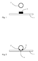
- a solar collector is fragmentary and schematic in the Figures 1 and 2 illustrated and comprises at least one plate-shaped absorber element 1, which may be selectively coated and made of metal, and standing with this in thermal contact, tubular conduit system 2 for the heat transport medium.
- the term absorber element is understood to mean both a plate-shaped element and narrow metal strips (so-called absorber fins) which are connected to the line system 2.
- the conduit system 2 is a meandering or harp-shaped pipe, wherein other configurations and shapes of the conduit system 2 are conceivable.
- the use of cross-section polygonal pipes instead of circular cross-sections is conceivable.
- the absorber element 1 and the conduit system 2 are connected to one another according to the invention by means of an adhesive 3 forming an adhesive bond.
- an adhesive 3 since almost every surface is contaminated during various operations in the manufacturing process, the surfaces of the components should or should be cleaned, for example, before applying the adhesive, ie before further operations.
- a plasma cleaning is a way to get absolutely clean, grease-free surfaces.
- the regions to be joined are cleaned, for example by means of a plasma process, which, among other things, degreases the surfaces to a high degree.
- plasma cleaning there are hardly any restrictions with regard to the material / material to be cleaned.
- temperature-sensitive plastics can be treated as well as metal, glass and ceramics.
- the plasma process must be adapted to the respective task in any case.
- a chemical pretreatment may be used to clean the areas to be joined, such as solvent vapor removal.
- an adhesion promoter to the regions of the absorber element 1 and / or the line system 2 to be connected. This is always necessary when different materials have to be glued together or when a particular adhesive is to be used because of its special properties, but the adhesive does not adhere sufficiently well on one of the two adhesive partners.
- the multi-component adhesive 3 is applied to the regions of the absorber element 1 to be joined.
- the application is preferably carried out automatically.
- a two-component silicone adhesive is used as the adhesive 3, which has a good thermal conductivity and exceptionally high adhesion properties over a high temperature range.
- this adhesive 3 is UV-resistant and degassing after rapid curing.
- PACTAN 8071 and Novosil VP 6431 from OTTO Chemie are mentioned here.
- the two components (adhesive and hardener) of the adhesive 3 are in liquid to pasty form and must be mixed together before application in a certain mixing ratio, the mixing ratio of adhesive and hardener usually between 100: 15 to 100: 30 parts by weight, in Individual cases even with 1: 1 volume fractions.
- PACTAN 8071 is used in a mixing ratio of 1: 1 and Novosil VP 6431 in a mixing ratio of 100: 14.
- the mixing of the two components and the subsequent application of the two-component silicone adhesive takes place in a fully automated Process step, wherein, for example, a static, static-dynamic or dynamic mixing unit with metering pump and mixing head, the adhesive 3 in a predetermined amount and in a predetermined mixing ratio on the absorber element 1 or on the line system 2 or both on absorber element 1 and 2 line system applies.
- a static, static-dynamic or dynamic mixing unit with metering pump and mixing head the adhesive 3 in a predetermined amount and in a predetermined mixing ratio on the absorber element 1 or on the line system 2 or both on absorber element 1 and 2 line system applies.
- the components of the solar collector to be connected ie the absorber element 1 and the line system 2 are arranged or positioned in their assembly position.
- the absorber element 1 is held or fixed by means of a vacuum clamping table, which, however, can take place even before the application of the adhesive 3.
- the line system 2 is then transported, for example as part of an automated method step, by a robot unit to the absorber element 1 fixed on the vacuum table.
- the absorber element 1 and the conduit system 2 are then temporarily releasably fixed, for example, by means of clips or other mechanical fastening means. In this case, the arrangement or joining of the two parts to one another can take place in an automated method step.
- This automated step comprises that the conduit system 2 and the absorber element 1 are pressed against each other such that the conduit system rests directly on the absorber element and is in complete thermal contact with it both in line contact 4 as well.
- This arrangement of both components, in which they are in line contact 4 corresponds to the assembly position.
- fastening means can then be manually or automatically attached to the arrangement and releasable fixing of the absorber element 1 and the conduit system 2 in the assembly position, so that a partially automated process step is present.
- the curing of the adhesive bond ie up to a sufficient strength for further processing ability, remain Absorber element 1 and the conduit system 2 fixed, with a low fixing pressure is sufficient.
- the curing of the adhesive 3 by means of contactless energy is introduced into the adhesive 3, so that after curing, the absorber element 1 and the line system 2 are in line contact 4 and by means of the line contact 4 arranged adhesive 3 (see FIG. 2 ).
- the line contact 4 is a portion of the outer wall of the circular cross-section conduit system 2 directly and without gaps on the absorber element 1. In, for example, quadrangular piping systems, there would be a surface contact between the outer wall of the piping system and the absorber element 1.
- the absorber element 1 and the line system 2 are introduced into a space which is separable from the environment for hardening the adhesive.
- This space is adapted to the outer dimensions of the components to be connected and has a plurality of hot air nozzles, can be directed by a hot or heated air flow directly and selectively to the multi-component adhesive 3 and the adhesive bond.
- the room is separated from the environment, with the total temperature inside the room rising to 60 ° C to 120 ° C.
- the nozzles are directed to the adhesive bond or only hot air nozzles are applied, whose air flow meets the adhesive bond.
- the multi-component adhesive 3 then cures at a temperature between 60 ° C and 120 ° C. There is a temperature monitoring by means of suitable sensors, so that it is ensured that the adhesive 3 or the silicone compound is not damaged.
- the contactless introduction of energy into the multicomponent adhesive 3 causes an accelerated reaction of the silicone composition and favors a fast curing or rapid curing of the multi-component adhesive 3, so that in a relatively short time the adhesive bond between the absorber element 1 and conduit system 2 has a minimum strength or further processing strength.
- An alternative method step for non-contact introduction of energy into the multi-component adhesive 3 can take place via the line system without introduction of the components to be connected in a space separated from the environment.
- heat is transferred via the conduit system by means of generating a flow of current in the conduit system to the adhesive for curing of the adhesive 3, wherein after a cycle time of about 80 to 180 seconds, a sufficient further processing strength is achieved.
- a required further processing strength is achieved after a cycle time of about 75 to 180 seconds.
- the adhesive bond between absorber element 1 and line system 2 can also cure at room temperature, in which case the required further processing stability is achieved after a cycle time of approximately 10 to 90 minutes.
- a specially provided step of cooling is not required in this type of adhesive bonding by means of the multi-component adhesive 3 due to the accelerated curing reaction.
- the holding devices and previously attached mechanical fixing devices can then be loosened and / or removed before the absorber element 1 and the line system 2 connected thereto are supplied with further processing steps.
- the absorber element 1 and the conduit system 2 are after rapid curing by means of the adhesive connection in the case of the circular tube-shaped conduit system 2 in line contact 4, ie a portion of the outer wall of the conduit system 2 is directly and without gaps on the absorber element 1.
- the two-component adhesive comprising contact-free energy input curing adhesive bond connects the absorber element 1 and the conduit system 2 elastically together, so that material expansion of absorber element 1 and / or conduit system 2 can be compensated due to strong temperature changes by the elastic adhesive bond.
- This adhesive connection ensures a uniform distribution of stress over the entire joining region of absorber element 1 and line system 2 and the compensation of different coefficients of expansion of absorber element 1 and line system 2.
- solar collectors with an adhesive bond between the absorber element and the line system can be created, which have a comparable or better efficiency with welded absorbers and at the same time lower production costs.
- the invention also has the advantage that this compound is not subject to mechanical voltage changes (for example, due to strong temperature changes), but rather the elastic or flexible adhesive connection always the line contact 4 of the absorber element and the line system, which is important for the efficiency of the solar collector guaranteed.
- this compound is not subject to mechanical voltage changes (for example, due to strong temperature changes), but rather the elastic or flexible adhesive connection always the line contact 4 of the absorber element and the line system, which is important for the efficiency of the solar collector guaranteed.
- the multicomponent adhesive decomposes into its components (for example silicon) and the adhesive bond between the absorber element and the line system is released.
- the invention has advantages over a laser welding process, because the compounds of the laser welding are alloys that solve it consuming and then to dispose of.
- the components of the solar collector according to the invention can be reused.
- the method described above is not only suitable for connecting an absorber element and a line system with one another.
- the adhesive bond with rapid curing is also suitable to realize other connections of the solar collector, such as the connection of the collector frame and glass cover or collector frame and rear wall, with high reliability, the method of the invention can be adapted for such compounds to the cycle times of series production ,
Landscapes
- Engineering & Computer Science (AREA)
- Chemical & Material Sciences (AREA)
- Sustainable Energy (AREA)
- Life Sciences & Earth Sciences (AREA)
- Physics & Mathematics (AREA)
- Sustainable Development (AREA)
- Dispersion Chemistry (AREA)
- Thermal Sciences (AREA)
- Combustion & Propulsion (AREA)
- Mechanical Engineering (AREA)
- General Engineering & Computer Science (AREA)
- Adhesives Or Adhesive Processes (AREA)
- Photovoltaic Devices (AREA)
Priority Applications (2)
| Application Number | Priority Date | Filing Date | Title |
|---|---|---|---|
| EP10154031A EP2362157A1 (fr) | 2010-02-18 | 2010-02-18 | Collecteur solaire |
| PCT/EP2011/052361 WO2011101413A2 (fr) | 2010-02-18 | 2011-02-17 | Capteur solaire |
Applications Claiming Priority (1)
| Application Number | Priority Date | Filing Date | Title |
|---|---|---|---|
| EP10154031A EP2362157A1 (fr) | 2010-02-18 | 2010-02-18 | Collecteur solaire |
Publications (1)
| Publication Number | Publication Date |
|---|---|
| EP2362157A1 true EP2362157A1 (fr) | 2011-08-31 |
Family
ID=42340670
Family Applications (1)
| Application Number | Title | Priority Date | Filing Date |
|---|---|---|---|
| EP10154031A Withdrawn EP2362157A1 (fr) | 2010-02-18 | 2010-02-18 | Collecteur solaire |
Country Status (2)
| Country | Link |
|---|---|
| EP (1) | EP2362157A1 (fr) |
| WO (1) | WO2011101413A2 (fr) |
Citations (10)
| Publication number | Priority date | Publication date | Assignee | Title |
|---|---|---|---|---|
| GB2183817A (en) * | 1985-11-12 | 1987-06-10 | Robert Dominic Walker | Heat exchange elements |
| DE19907518C1 (de) * | 1999-02-22 | 2000-11-30 | Saskia Solar Und Energietechni | Sonnenkollektor |
| DE10126135A1 (de) * | 2001-05-29 | 2002-12-05 | Ufe Solar Gmbh I Ins | Verfahren zur Herstellung von Absorbern, insbesondere für thermische Solaranlagen |
| DE20216297U1 (de) * | 2002-10-23 | 2003-01-09 | Rheinzink GmbH & Co. KG, 45711 Datteln | Heliothermischer Flachkollektor-Modul in Sandwichbauweise |
| DE10230296A1 (de) * | 2002-07-05 | 2004-01-15 | Stadur Produktions Gmbh & Co. Kg | Sandwichelement mit integriertem Rohrsystem, Verfahren zur Herstellung und Verwendung desselben |
| EP1630514A1 (fr) * | 2004-08-16 | 2006-03-01 | Isocoll Chemie GmbH | Procédé pour la fixation d'un tube sur une plaque |
| EP1775525A1 (fr) * | 2005-10-11 | 2007-04-18 | Green One Tec Solar-Industrie GmbH | Méthode d'assemblage d'un collecteur de soleil |
| EP1873843A2 (fr) * | 2006-06-26 | 2008-01-02 | Fototherm S.r.l. | Installation photovoltaïque |
| DE102008008015A1 (de) * | 2008-02-07 | 2009-08-13 | Erich Terbrack | Kollektorelement eines Sonnenkollektors und Sonnenkollektor |
| DE102008009371A1 (de) * | 2008-02-14 | 2009-08-20 | Henkel Ag & Co. Kgaa | Verfahren zur Herstellung eines Wärmetauschers |
-
2010
- 2010-02-18 EP EP10154031A patent/EP2362157A1/fr not_active Withdrawn
-
2011
- 2011-02-17 WO PCT/EP2011/052361 patent/WO2011101413A2/fr not_active Ceased
Patent Citations (10)
| Publication number | Priority date | Publication date | Assignee | Title |
|---|---|---|---|---|
| GB2183817A (en) * | 1985-11-12 | 1987-06-10 | Robert Dominic Walker | Heat exchange elements |
| DE19907518C1 (de) * | 1999-02-22 | 2000-11-30 | Saskia Solar Und Energietechni | Sonnenkollektor |
| DE10126135A1 (de) * | 2001-05-29 | 2002-12-05 | Ufe Solar Gmbh I Ins | Verfahren zur Herstellung von Absorbern, insbesondere für thermische Solaranlagen |
| DE10230296A1 (de) * | 2002-07-05 | 2004-01-15 | Stadur Produktions Gmbh & Co. Kg | Sandwichelement mit integriertem Rohrsystem, Verfahren zur Herstellung und Verwendung desselben |
| DE20216297U1 (de) * | 2002-10-23 | 2003-01-09 | Rheinzink GmbH & Co. KG, 45711 Datteln | Heliothermischer Flachkollektor-Modul in Sandwichbauweise |
| EP1630514A1 (fr) * | 2004-08-16 | 2006-03-01 | Isocoll Chemie GmbH | Procédé pour la fixation d'un tube sur une plaque |
| EP1775525A1 (fr) * | 2005-10-11 | 2007-04-18 | Green One Tec Solar-Industrie GmbH | Méthode d'assemblage d'un collecteur de soleil |
| EP1873843A2 (fr) * | 2006-06-26 | 2008-01-02 | Fototherm S.r.l. | Installation photovoltaïque |
| DE102008008015A1 (de) * | 2008-02-07 | 2009-08-13 | Erich Terbrack | Kollektorelement eines Sonnenkollektors und Sonnenkollektor |
| DE102008009371A1 (de) * | 2008-02-14 | 2009-08-20 | Henkel Ag & Co. Kgaa | Verfahren zur Herstellung eines Wärmetauschers |
Also Published As
| Publication number | Publication date |
|---|---|
| WO2011101413A3 (fr) | 2012-01-19 |
| WO2011101413A2 (fr) | 2011-08-25 |
Similar Documents
| Publication | Publication Date | Title |
|---|---|---|
| DE60202349T2 (de) | Bautechnischer schmelzkleber und entsprechende verfahren | |
| EP3046813B1 (fr) | Procédé d'assemblage | |
| DE102008010884B4 (de) | Fügeverfahren | |
| DE102008060116A1 (de) | Verfahren zur Herstellung einer Lageranordnung und Lageranordnung | |
| DE102010004792A1 (de) | Verfahren zum Festlegen eines Lagerrings an oder in einem Bauteil | |
| DE102015005407A1 (de) | Rührreibschweißen von Thermoplasten | |
| EP2652418B1 (fr) | Module de collecteurs solaires avec un système de fixation pour fixer un élément miroir sur une structure de support | |
| DE102016203363A1 (de) | Verfahren zum stoffschlüssigen Verbinden eines Aluminiumgussbauteils mit einem Fügepartner und Bauteil | |
| DE102008000517B4 (de) | Verfahren zum druckdichten Fügen eines metallischen Lenkgetriebegehäuses mit einem Kunststoffgehäusedeckel | |
| EP3194878A1 (fr) | Procédé pour produire un échangeur de chaleur | |
| EP2362157A1 (fr) | Collecteur solaire | |
| DE102012014756A1 (de) | Verfahren und Vorrichtung zum Verbinden zumindest zweier Bestandteile einer Brennstoffzelle | |
| DE102010048118A1 (de) | Verfahren zur Herstellung eines Hybridbauteils und Kraftfahrzeughybridbauteil | |
| WO2011128118A1 (fr) | Machine de soudage par ultrasons de type omega | |
| DE10312815A1 (de) | Verfahren zum Kontaminationstoleranten Kleben von Fügeteilen | |
| DE102006056489A1 (de) | Verfahren zur Herstellung eines Stahl-/Aluminium-Verbundbauteils | |
| DE102020134380A1 (de) | Kühlbauteil zum Abführen von Wärme | |
| DE102014217075A1 (de) | Verfahren zum Herstellen einer Temperiervorrichtung und Temperiervorrichtung | |
| WO2017021152A1 (fr) | Procédé de fabrication d'un refroidisseur à plaques empilées et refroidisseur à plaques empilées | |
| DE102007010540A1 (de) | Verfahren zum hochfesten Kleben von Bauteilen | |
| DE102004013845B3 (de) | Vorrichtung und Verfahren zum Auftragen von Klebstoff | |
| DE102006010578B3 (de) | Solarkollektor | |
| DE102014201014A1 (de) | Verfahren zum Aufbringen eines Flussmittels | |
| WO2002087872A1 (fr) | Platine de toles pouvant etre transformee en composant forme | |
| DE102015215041A1 (de) | Verfahren zum Herstellen eines Wärmeübertragers und Wärmeübertrager |
Legal Events
| Date | Code | Title | Description |
|---|---|---|---|
| PUAI | Public reference made under article 153(3) epc to a published international application that has entered the european phase |
Free format text: ORIGINAL CODE: 0009012 |
|
| AK | Designated contracting states |
Kind code of ref document: A1 Designated state(s): AT BE BG CH CY CZ DE DK EE ES FI FR GB GR HR HU IE IS IT LI LT LU LV MC MK MT NL NO PL PT RO SE SI SK SM TR |
|
| AX | Request for extension of the european patent |
Extension state: AL BA RS |
|
| STAA | Information on the status of an ep patent application or granted ep patent |
Free format text: STATUS: THE APPLICATION IS DEEMED TO BE WITHDRAWN |
|
| 18D | Application deemed to be withdrawn |
Effective date: 20120301 |